drain bolt INFINITI QX56 2007 Factory Owner's Manual
[x] Cancel search | Manufacturer: INFINITI, Model Year: 2007, Model line: QX56, Model: INFINITI QX56 2007Pages: 3061, PDF Size: 64.56 MB
Page 1773 of 3061
PRECAUTIONSEM-3
< SERVICE INFORMATION >
C
DE
F
G H
I
J
K L
M A
EM
NP
O
SERVICE INFORMATION
PRECAUTIONS
Precaution for Supplemental
Restraint System (SRS) "AIR BAG" and "SEAT BELT
PRE-TENSIONER"
INFOID:0000000003531508
The Supplemental Restraint System such as “A IR BAG” and “SEAT BELT PRE-TENSIONER”, used along
with a front seat belt, helps to reduce the risk or severi ty of injury to the driver and front passenger for certain
types of collision. This system includes seat belt switch inputs and dual stage front air bag modules. The SRS
system uses the seat belt switches to determine the front air bag deployment, and may only deploy one front
air bag, depending on the severity of a collision and w hether the front occupants are belted or unbelted.
Information necessary to service the system safely is included in the SRS and SB section of this Service Man-
ual.
WARNING:
• To avoid rendering the SRS inoper ative, which could increase the risk of personal injury or death in
the event of a collision which would result in air bag inflation, all maintenance must be performed by
an authorized NISSAN/INFINITI dealer.
• Improper maintenance, including in correct removal and installation of the SRS, can lead to personal
injury caused by unintentional act ivation of the system. For removal of Spiral Cable and Air Bag
Module, see the SRS section.
• Do not use electrical test equipm ent on any circuit related to the SRS unless instructed to in this
Service Manual. SRS wiring harnesses can be identi fied by yellow and/or orange harnesses or har-
ness connectors.
Precaution for Drain Engine CoolantINFOID:0000000003531509
Drain engine coolant when engine is cooled.
Precaution for Disco nnecting Fuel PipingINFOID:0000000003531510
• Before starting work, make sure no fire or spark producing items are in the work area.
• Release fuel pressure before disconnecting and disassembly.
• After disconnecting pipes, plug openings to stop fuel leakage.
Precaution for Removal and DisassemblyINFOID:0000000003531511
• When instructed to use special service tools, use the spec ified tools. Always be careful to work safely, avoid
forceful or uninstructed operations.
• Exercise maximum care to avoid damage to mating or sliding surfaces.
• Cover openings of engine system with tape or the equiva lent, if necessary, to seal out foreign materials.
• Mark and arrange disassembly parts in an organized way for easy troubleshooting and assembly.
• When loosening nuts and bolts, as a basic rule, start with the one furthest outside, then the one diagonally
opposite, and so on. If the order of loosening is specif ied, do exactly as specified. Power tools may be used
where noted in the step.
Precaution for Inspection, Repair and ReplacementINFOID:0000000003531512
Before repairing or replacing, thoroughly inspect parts. Inspect new replacement parts in the same way, and
replace if necessary.
Precaution for Assembly and InstallationINFOID:0000000003531513
• Use torque wrench to tighten bolts or nuts to specification.
• When tightening nuts and bolts, as a basic rule, equally tighten in several different steps starting with the ones in center, then ones on inside and outside diagonally in this order. If the order of tightening is specified,
do exactly as specified.
• Replace with new gasket, packing, oil seal or O-ring.
• Thoroughly wash, clean, and air-blow each part. Carefully check engine oil or engine coolant passages for any restriction and blockage.
• Avoid damaging sliding or mating surfaces. Completely remove foreign materials such as cloth lint or dust. Before assembly, oil sliding surfaces well.
Page 1774 of 3061
EM-4
< SERVICE INFORMATION >
PRECAUTIONS
• Release air within route when refilling after draining engine coolant.
• Before starting engine, apply fuel pressure to fuel lines with turning ignition switch ON (with engine stopped).
Then make sure that there are no leaks at fuel line connections.
• After repairing, start engine and increase engine s peed to check engine coolant, fuel, oil, and exhaust sys-
tems for leakage.
Parts Requiring Angular TighteningINFOID:0000000003531514
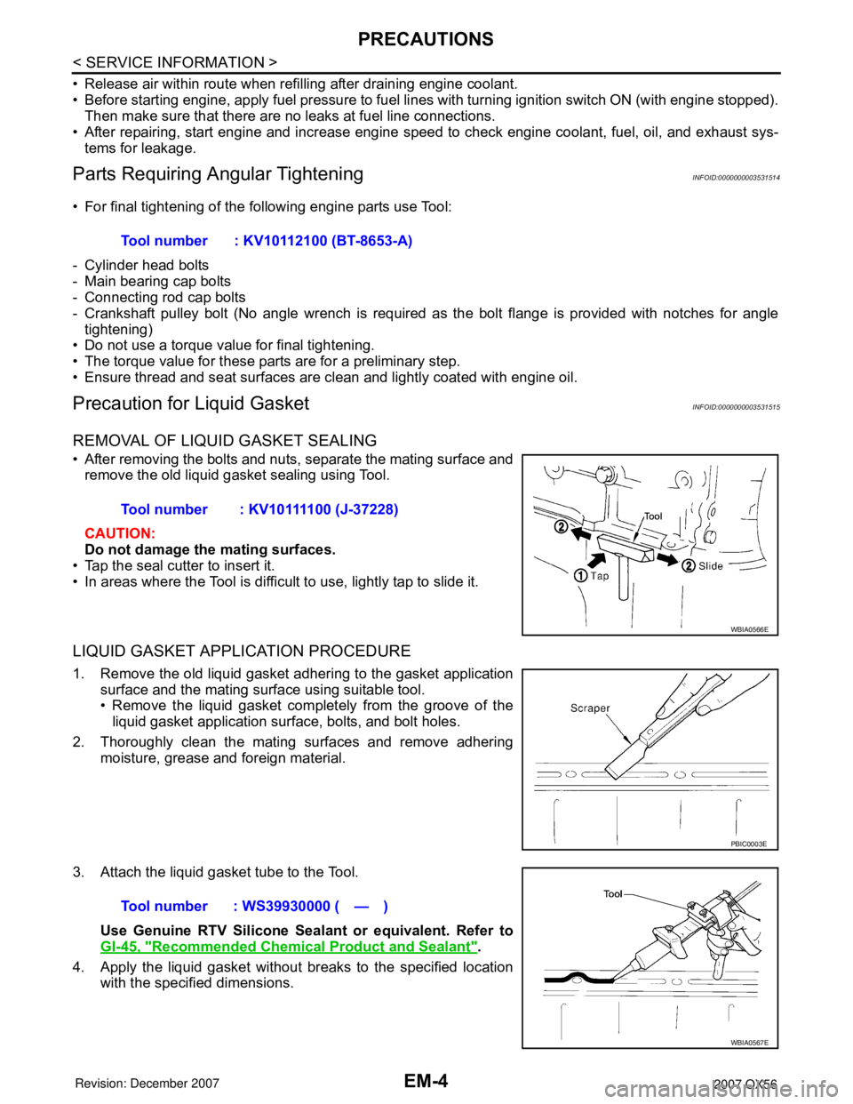
• For final tightening of the following engine parts use Tool:
- Cylinder head bolts
- Main bearing cap bolts
- Connecting rod cap bolts
- Crankshaft pulley bolt (No angle wrench is required as the bolt flange is provided with notches for angle tightening)
• Do not use a torque value for final tightening.
• The torque value for these parts are for a preliminary step.
• Ensure thread and seat surfaces are clean and lightly coated with engine oil.
Precaution for Liquid GasketINFOID:0000000003531515
REMOVAL OF LIQUID GASKET SEALING
• After removing the bolts and nuts, separate the mating surface and
remove the old liquid gasket sealing using Tool.
CAUTION:
Do not damage the mating surfaces.
• Tap the seal cutter to insert it.
• In areas where the Tool is difficult to use, lightly tap to slide it.
LIQUID GASKET APPLICATION PROCEDURE
1. Remove the old liquid gasket adhering to the gasket application surface and the mating surface using suitable tool.
• Remove the liquid gasket completely from the groove of theliquid gasket application surface, bolts, and bolt holes.
2. Thoroughly clean the mating surfaces and remove adhering moisture, grease and foreign material.
3. Attach the liquid gasket tube to the Tool. Use Genuine RTV Silicone Seal ant or equivalent. Refer to
GI-45, "
Recommended Chemical Product and Sealant".
4. Apply the liquid gasket without breaks to the specified location with the specified dimensions.Tool number : KV10112100 (BT-8653-A)
Tool number : KV10111100 (J-37228)
WBIA0566E
PBIC0003E
Tool number : WS39930000 ( — )
WBIA0567E
Page 1794 of 3061
EM-24
< SERVICE INFORMATION >
OIL PAN AND OIL STRAINER
OIL PAN AND OIL STRAINER
Removal and InstallationINFOID:0000000003531528
REMOVAL
WARNING:
To avoid the danger of being scalded, never drain the engine oil when the engine is hot.
1. Remove the engine. Refer to EM-74, "
Removal and Installation".
2. Remove the oil pan (lower) using the following steps.
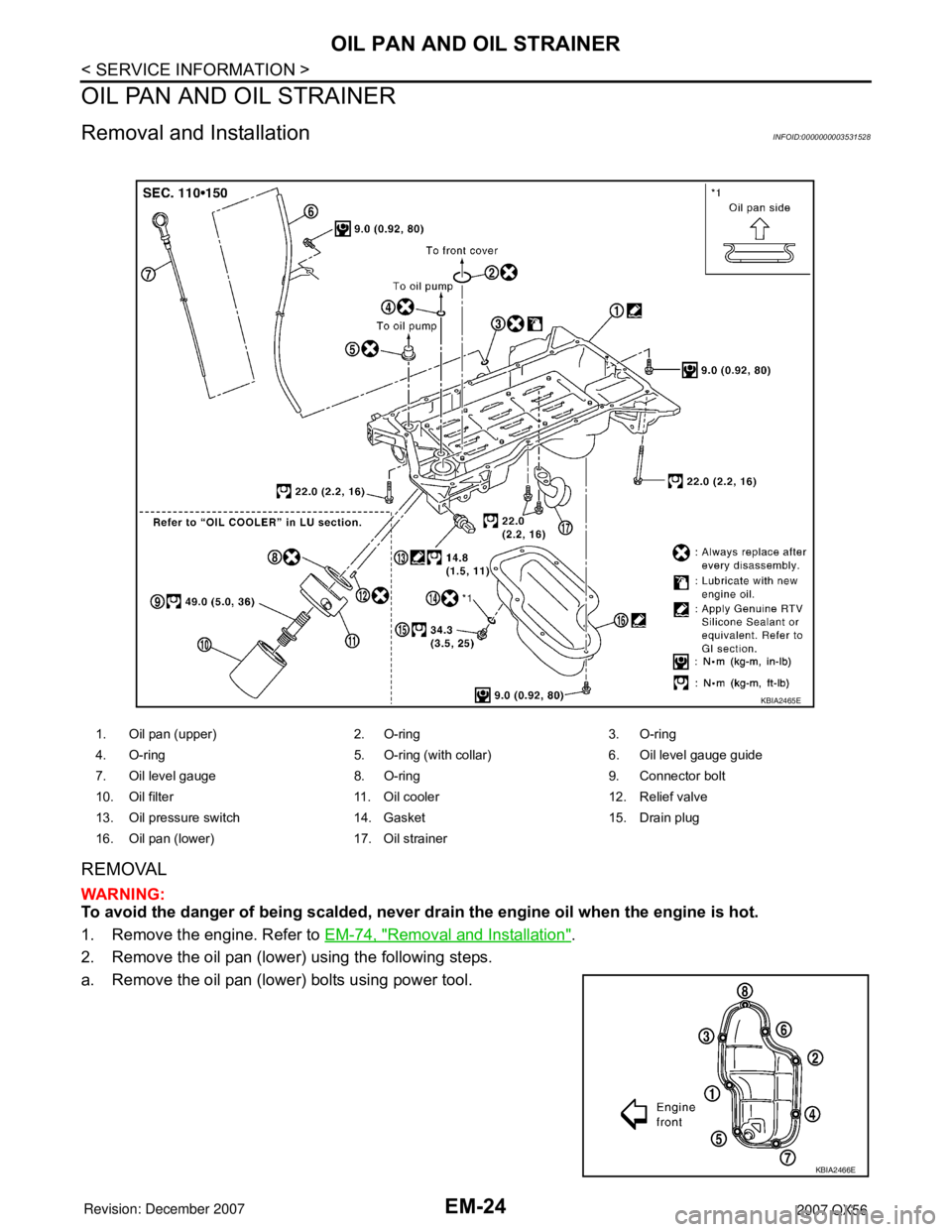
a. Remove the oil pan (lower) bolts using power tool.
1. Oil pan (upper) 2. O-ring 3. O-ring
4. O-ring 5. O-ring (with collar) 6. Oil level gauge guide
7. Oil level gauge 8. O-ring 9. Connector bolt
10. Oil filter 11. Oil cooler 12. Relief valve
13. Oil pressure switch 14. Gasket 15. Drain plug
16. Oil pan (lower) 17. Oil strainer
KBIA2465E
KBIA2466E
Page 1844 of 3061
EM-74
< SERVICE INFORMATION >
ENGINE ASSEMBLY
ENGINE ASSEMBLY
Removal and InstallationINFOID:0000000003531544
WARNING:
• Situate vehicle on a flat and solid surface.
• Place chocks at front and back of rear wheels.
• For engines not equipped with engine slingers, attach proper slingers and bolts described in PARTS
CATALOG.
CAUTION:
• Always be careful to work safely, avoid forceful or uninstructed operations.
• Do not start working until exhaust system and engine coolant are cooled sufficiently.
• If items or work required are not covered by the engine section, refer to the applicable sections.
• Always use the support point specified for lifting.
• Use either 2-point lift type or separate type lift. If board-on type is used for unavoidable reasons,
support at the rear axle jacking point with transmission jack or similar tool before starting work, in
preparation for the backward shift of center of gravity.
• For supporting points for lifting and jacking point at rear axle, refer to GI-40, "
Garage Jack and
Safety Stand".
REMOVAL
Preparation
1. Drain the engine coolant. Refer to CO-9, "Changing Engine Coolant".
2. Partially drain the A/T fluid. Refer to AT-13, "
Changing Automatic Transmission Fluid (ATF)".
3. Release the fuel pressure. Refer to EC-80, "
Fuel Pressure Check".
4. Remove the engine hood. Refer to BL-12, "
Removal and Installation of Hood Assembly".
5. Remove the cowl extension. Refer to EI-17, "
Removal and Installation".
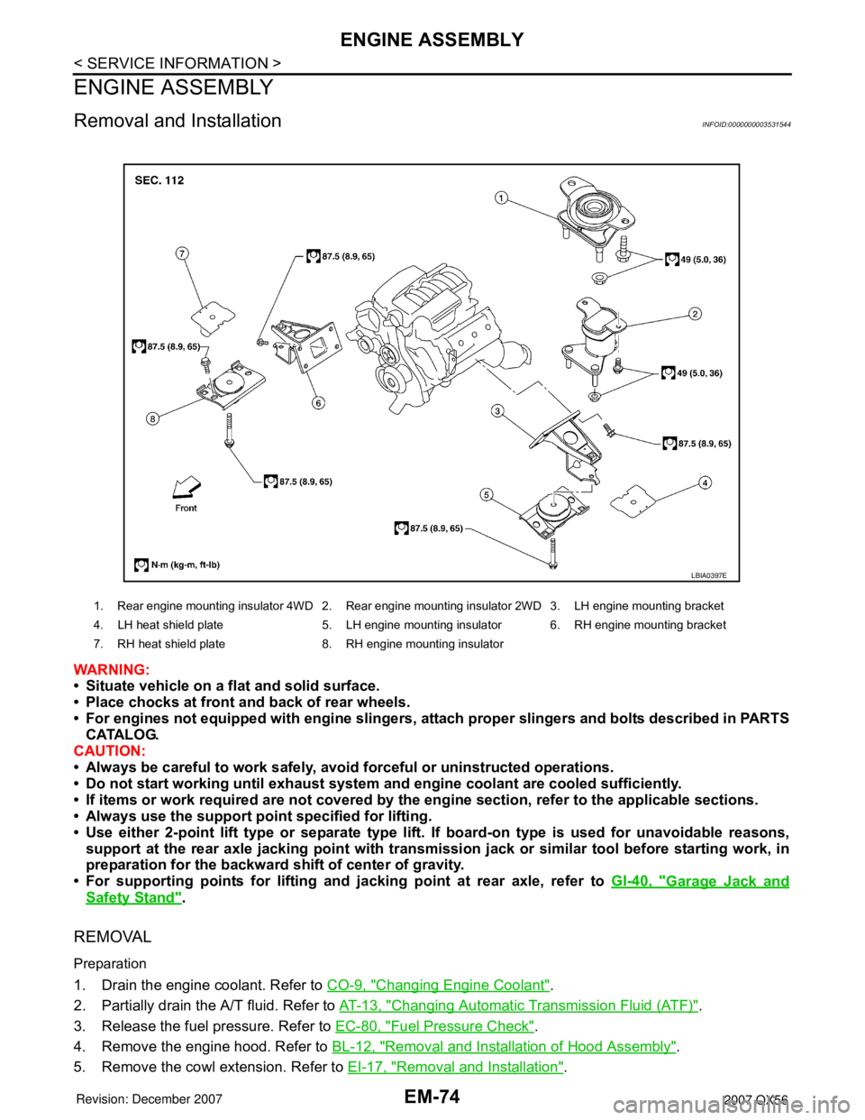
1. Rear engine mounting insulator 4WD 2. Rear engine mounting insulator 2WD 3. LH engine mounting bracket
4. LH heat shield plate 5. LH engine mounting insulator 6. RH engine mounting bracket
7. RH heat shield plate 8. RH engine mounting insulator
LBIA0397E
Page 1916 of 3061

FRONT FINAL DRIVE ASSEMBLY
FFD-17
< SERVICE INFORMATION >
C
E
F
G
H
I
J
K
L
MA
B
FFD
N
O
P Backlash
1. Fit a dial indicator to the drive gear face to measure the back-
lash.
• If the backlash is outside of the specification, adjust each side
bearing adjuster.
CAUTION:
Do not change the side bearing adjusters by different
amounts as it will change the side bearing preload torque.
Companion Flange Runout
1. Rotate companion flange and check for runout on the compan-
ion flange face (inner side of the bolt holes) and companion
flange inner side (socket diameter) using suitable tool.
2. If the runout is outside the runout limit, follow the procedure
below to adjust.
a. Rotate the companion flange on the drive pinion by 90°, 180°
and 270° while checking for the position where the runout is minimum.
b. If the runout is still outside of the runout limit after the companion flange has been rotated on the drive pin-
ion, possible cause could be an assembly malfunction of drive pinion and drive pinion bearing or a mal-
functioning drive pinion bearing.
c. If the runout is still outside of the runout limit after repair of the assembly of drive pinion and drive pinion
bearing or drive pinion bearing, replace the companion flange.
DISASSEMBLY
Differential Assembly
1. Drain the differential gear oil if necessary.Backlash: 0.12 - 0.20 mm (0.0050 - 0.0079 in)
SPD513
If the backlash is greater than specification:
Loosen side bearing adjuster A and tighten side bear-
ing adjuster B by the same amount.
If the backlash is less than specification:
Loosen side bearing adjuster B and tighten side bear-
ing adjuster A by the same amount.
SDIA2262E
Runout limit
Companion flange face: 0.10 mm (0.0039 in)
Companion flange inner side: 0.13 mm (0.0051 in)
SDIA2078E
Page 2385 of 3061
CHASSIS AND BODY MAINTENANCE
MA-23
< SERVICE INFORMATION >
C
D
E
F
G
H
I
J
K
MA
B
MA
N
O
P
10. Tighten the level gauge bolt to specification.
Changing Automatic Transmission Fluid (ATF)INFOID:0000000003533878
1. Drive the vehicle to warm up the ATF to 80° C (176° F).
2. Stop the engine.
3. Remove the ATF level gauge bolt.
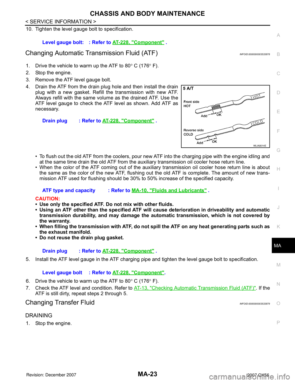
4. Drain the ATF from the drain plug hole and then install the drain
plug with a new gasket. Refill the transmission with new ATF.
Always refill with the same volume as the drained ATF. Use the
ATF level gauge to check the ATF level as shown. Add ATF as
necessary.
• To flush out the old ATF from the coolers, pour new ATF into the charging pipe with the engine idling and
at the same time drain the old ATF from the auxiliary transmission oil cooler hose return line.
• When the color of the ATF coming out of the auxiliary transmission oil cooler hose return line is about
the same as the color of the new ATF, flushing out the old ATF is complete. The amount of new trans-
mission ATF used for flushing should be 30% to 50% increase of the specified capacity.
CAUTION:
• Use only the specified ATF. Do not mix with other fluids.
• Using an ATF other than the specified ATF will cause deterioration in driveability and automatic
transmission durability, and may damage the automatic transmission, which is not covered by
the warranty.
• When filling the transmission with ATF, do not spill the ATF on any heat generating parts such as
the exhaust manifold.
• Do not reuse the drain plug gasket.
5. Install the ATF level gauge in the ATF charging pipe and tighten the level gauge bolt to specification.
6. Drive the vehicle to warm up the ATF to 80° C (176° F).
7. Check the ATF level and condition. Refer to AT-13, "
Checking Automatic Transmission Fluid (ATF)". If the
ATF is still dirty, repeat steps 2 through 5.
Changing Transfer FluidINFOID:0000000003533879
DRAINING
1. Stop the engine.Level gauge bolt: : Refer to AT-228, "
Component" .
Drain plug : Refer to AT-228, "
Component" .
WLIA0014E
ATF type and capacity : Refer to MA-10, "Fluids and Lubricants" .
Drain plug : Refer to AT-228, "
Component" .
Level gauge bolt : Refer to AT-228, "
Component".
Page 2507 of 3061
PS-16
< SERVICE INFORMATION >
POWER STEERING GEAR AND LINKAGE
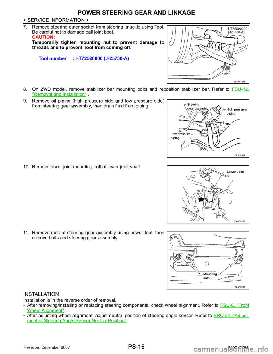
7. Remove steering outer socket from steering knuckle using Tool.
Be careful not to damage ball joint boot.
CAUTION:
Temporarily tighten mounting nut to prevent damage to
threads and to prevent Tool from coming off.
8. On 2WD model, remove stabilizer bar mounting bolts and reposition stabilizer bar. Refer to FSU-12,
"Removal and Installation" .
9. Remove oil piping (high pressure side and low pressure side)
from steering gear assembly, then drain fluid from piping.
10. Remove lower joint mounting bolt of lower joint shaft.
11. Remove nuts of steering gear assembly using power tool, then
remove bolts and steering gear assembly.
INSTALLATION
Installation is in the reverse order of removal.
• After removing/installing or replacing steering components, check wheel alignment. Refer to FSU-6, "
Front
Wheel Alignment" .
• After adjusting wheel alignment, adjust neutral position of steering angle sensor. Refer to BRC-54, "
Adjust-
ment of Steering Angle Sensor Neutral Position" . Tool number : HT72520000 (J-25730-A)
SDIA1434E
LGIA0032E
LGIA0029E
LGIA0024E
Page 2512 of 3061
POWER STEERING OIL PUMP
PS-21
< SERVICE INFORMATION >
C
D
E
F
H
I
J
K
L
MA
B
PS
N
O
P
POWER STEERING OIL PUMP
On-Vehicle Inspection and ServiceINFOID:0000000003532831
CHECKING RELIEF OIL PRESSURE
CAUTION:
Before starting work, confirm belt tension is proper.
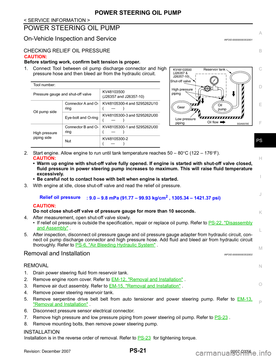
1. Connect Tool between oil pump discharge connector and high
pressure hose and then bleed air from the hydraulic circuit.
2. Start engine. Allow engine to run until tank temperature reaches 50 – 80°C (122 – 176°F).
CAUTION:
• Warm up engine with shut-off valve fully opened. If engine is started with shut-off valve closed,
fluid pressure in power steering pump increases to maximum. This will raise fluid temperature
excessively.
• Be careful not to contact hose with belt when engine is started.
3. With engine at idle, close shut-off valve and read the relief oil pressure.
CAUTION:
Do not close shut-off valve of pressure gauge for more than 10 seconds.
4. After measurement, open shut-off valve slowly.
• If relief oil pressure is outside the specification, repair or replace oil pump. Refer to PS-22, "
Disassembly
and Assembly" .
5. After inspection, disconnect oil pressure gauge and oil pressure gauge adapter from hydraulic circuit, con-
nect oil pump discharge connector and high pressure hose. Add fluid and bleed air from hydraulic circuit
thoroughly. Refer to PS-6, "
Air Bleeding Hydraulic System" .
Removal and InstallationINFOID:0000000003532832
REMOVAL
1. Drain power steering fluid from reservoir tank.
2. Remove engine room cover. Refer to EM-12, "
Removal and Installation" .
3. Remove air duct assembly. Refer to EM-15, "
Removal and Installation" .
4. Remove power steering reservoir tank.
5. Remove serpentine drive belt belt from auto tensioner and power steering pump. Refer to EM-13,
"Removal and Installation" .
6. Disconnect pressure sensor electrical connector.
7. Remove high pressure and low pressure piping from power steering oil pump. Refer to PS-23
.
8. Remove mounting bolts, then remove power steering pump.
INSTALLATION
Installation is in the reverse order of removal. Refer to PS-23 for tightening torque.
Tool number:
Pressure gauge and shut-off valveKV48103500
(J26357 and J26357-10)
Oil pump sideConnector A and O-
ringKV48105300-4 and 5295262U10
(—)
Eye-bolt and O-ringKV48105300-3 and 5295262U00
(—)
High pressure
piping sideConnector B and O-
ringKV48105300-1 and 5295262U00
(—)
NutKV48105300-2
( — )
SGIA0570E
Relief oil pressure
: 9.0 – 9.8 mPa (91.77 – 99.93 kg/cm2 , 1305.34 – 1421.37 psi)
Page 2554 of 3061

RF-22
< SERVICE INFORMATION >
SUNROOF
SUNROOF UNIT
Removal
CAUTION:
• Always work with a helper.
• When taking sunroof unit out, use shop cloths to protect the seats and trim from damage.
• After installing the sunroof unit and glass lid assembly, check gap adjustment to make sure there is
no malfunction.
1. Remove headlining. Refer to EI-37
.
2. Remove the sunroof glass lid assembly. Refer to "GLASS LID ASSEMBLY".
3. Remove overhead console bracket.
4. Disconnect front and rear drain hoses.
5. Remove front sunroof frame assembly bolts.
6. Remove rear sunroof bracket bolts.
7. Remove the sunroof frame assembly side bolts, then the sunroof unit.
Installation
1. Position the sunroof frame assembly and install the side bolts.
2. Install the sunroof brackets and bolts.
3. Install the front sunroof frame assembly bolts.
4. Connect front and rear drain hoses.
5. Install the overhead console bracket.
6. Install the sunroof glass lid assembly. Refer to "GLASS LID ASSEMBLY".
NOTE:
Adjust sunroof glass lid assembly gap and height, refer to RF-20, "
Fitting Adjustment".
7. Install headlining. Refer to EI-37
.
GLASS LID ASSEMBLY
Removal
1. Open sunshade assembly.
NOTE:
Be sure glass lid assembly is fully closed.
2. Remove side cover LH and RH.
3. Remove the glass lid assembly screws at the sunroof frame
assembly.
4. Remove the glass lid assembly.
Installation
1. Position glass lid assembly to sunroof frame assembly.
2. Install glass lid assembly screws.
NOTE:
First tighten left front screw, then right rear to prevent movement while tightening the remaining screws.
1. Glass lid assembly 2. Wind deflector 3. Rear drain hoses
4. Shade stoppers 5. Sunroof bracket 6. Sunshade assembly
7. Front drain hoses 8. Sunroof motor assembly 9. Sunroof frame assembly
10. Overhead console bracket 11. Side cover LH 12. Side cover RH
WIIA0252E
Page 2576 of 3061
REAR FINAL DRIVE ASSEMBLY
RFD-19
< SERVICE INFORMATION >
C
E
F
G
H
I
J
K
L
MA
B
RFD
N
O
P Backlash
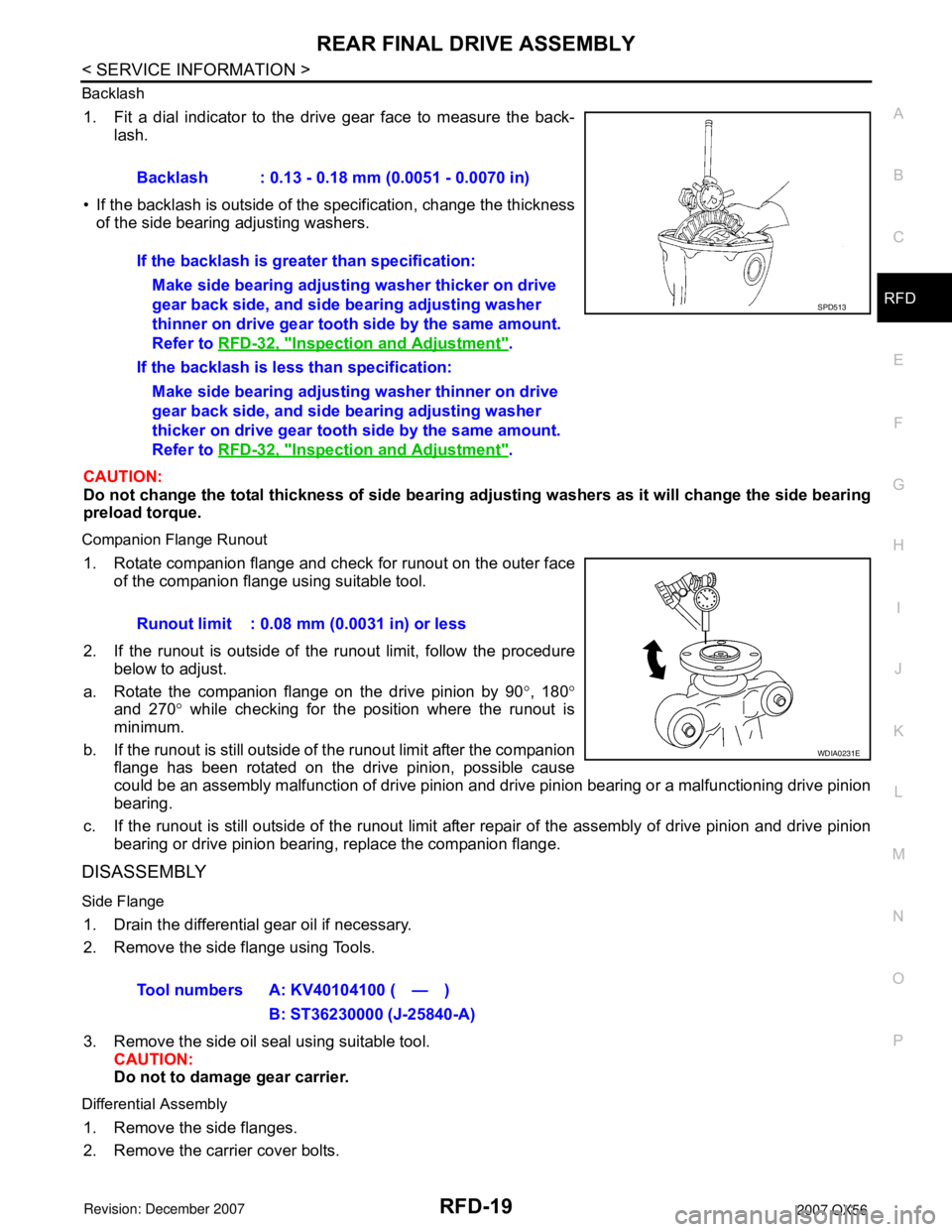
1. Fit a dial indicator to the drive gear face to measure the back-
lash.
• If the backlash is outside of the specification, change the thickness
of the side bearing adjusting washers.
CAUTION:
Do not change the total thickness of side bearing adjusting washers as it will change the side bearing
preload torque.
Companion Flange Runout
1. Rotate companion flange and check for runout on the outer face
of the companion flange using suitable tool.
2. If the runout is outside of the runout limit, follow the procedure
below to adjust.
a. Rotate the companion flange on the drive pinion by 90°, 180°
and 270° while checking for the position where the runout is
minimum.
b. If the runout is still outside of the runout limit after the companion
flange has been rotated on the drive pinion, possible cause
could be an assembly malfunction of drive pinion and drive pinion bearing or a malfunctioning drive pinion
bearing.
c. If the runout is still outside of the runout limit after repair of the assembly of drive pinion and drive pinion
bearing or drive pinion bearing, replace the companion flange.
DISASSEMBLY
Side Flange
1. Drain the differential gear oil if necessary.
2. Remove the side flange using Tools.
3. Remove the side oil seal using suitable tool.
CAUTION:
Do not to damage gear carrier.
Differential Assembly
1. Remove the side flanges.
2. Remove the carrier cover bolts.Backlash : 0.13 - 0.18 mm (0.0051 - 0.0070 in)
If the backlash is greater than specification:
Make side bearing adjusting washer thicker on drive
gear back side, and side bearing adjusting washer
thinner on drive gear tooth side by the same amount.
Refer to RFD-32, "
Inspection and Adjustment".
If the backlash is less than specification:
Make side bearing adjusting washer thinner on drive
gear back side, and side bearing adjusting washer
thicker on drive gear tooth side by the same amount.
Refer to RFD-32, "
Inspection and Adjustment".
SPD513
Runout limit : 0.08 mm (0.0031 in) or less
WDIA0231E
Tool numbers A: KV40104100 ( — )
B: ST36230000 (J-25840-A)