fuel type INFINITI QX56 2007 Factory Service Manual
[x] Cancel search | Manufacturer: INFINITI, Model Year: 2007, Model line: QX56, Model: INFINITI QX56 2007Pages: 3061, PDF Size: 64.56 MB
Page 5 of 3061
2007
QUICK REFERENCE CHART: QX56
Drive Belt Deflection and Tension
Spark Plug (Platinum Tipped)
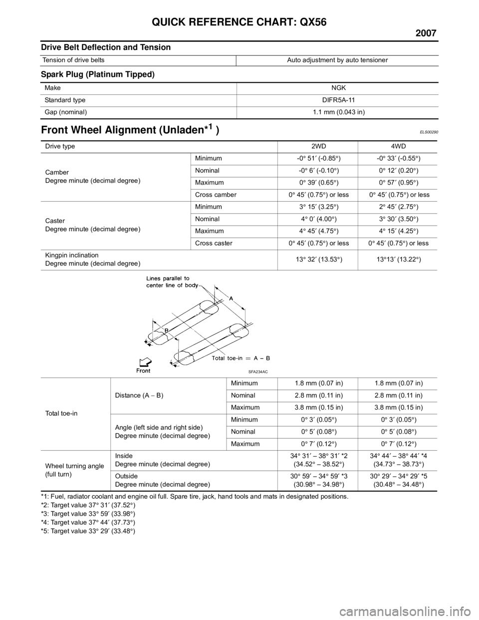
Front Wheel Alignment (Unladen*1 )ELS00290
*1: Fuel, radiator coolant and engine oil full. Spare tire, jack, hand tools and mats in designated positions.
*2: Target value 37° 31 ′ (37.52 °)
*3: Target value 33 ° 59 ′ (33.98 °)
*4: Target value 37 ° 44 ′ (37.73 °)
*5: Target value 33 ° 29 ′ (33.48 °)
Tension of drive belts Auto adjustment by auto tensioner
Make NGK
Standard type DIFR5A-11
Gap (nominal) 1.1 mm (0.043 in)
Drive type2WD 4WD
Camber
Degree minute (decimal degree) Minimum -0
° 51 ′ (-0.85 °)-0 ° 33 ′ (-0.55 °)
Nominal -0 ° 6 ′ (-0.10 °)0 ° 12 ′ (0.20 °)
Maximum 0 ° 39 ′ (0.65 °)0 ° 57 ′ (0.95 °)
Cross camber 0 ° 45 ′ (0.75 °) or less 0 ° 45 ′ (0.75 °) or less
Caster
Degree minute (decimal degree) Minimum 3
° 15 ′ (3.25 °)2 ° 45 ′ (2.75 °)
Nominal 4 ° 0 ′ (4.00 °)3 ° 30 ′ (3.50 °)
Maximum 4 ° 45 ′ (4.75 °)4 ° 15 ′ (4.25 °)
Cross caster 0 ° 45 ′ (0.75 °) or less 0 ° 45 ′ (0.75 °) or less
Kingpin inclination
Degree minute (decimal degree) 13
° 32 ′ (13.53 °)13 °13 ′ (13.22 °)
Total toe-in Distance (A
− B) Minimum 1.8 mm (0.07 in) 1.8 mm (0.07 in)
Nominal 2.8 mm (0.11 in) 2.8 mm (0.11 in)
Maximum 3.8 mm (0.15 in) 3.8 mm (0.15 in)
Angle (left side and right side)
Degree minute (decimal degree) Minimum 0
° 3 ′ (0.05 °)0 ° 3 ′ (0.05 °)
Nominal 0 ° 5 ′ (0.08 °)0 ° 5 ′ (0.08 °)
Maximum 0 ° 7 ′ (0.12 °)0 ° 7 ′ (0.12 °)
Wheel turning angle
(full turn) Inside
Degree minute (decimal degree)
34
° 31 ′ – 38 ° 31 ′ *2
(34.52 ° – 38.52 °) 34
° 44 ′ – 38 ° 44 ′ *4
(34.73 ° – 38.73 °)
Outside
Degree minute (decimal degree) 30
° 59 ′ – 34 ° 59 ′ *3
(30.98 ° – 34.98 °) 30
° 29 ′ – 34 ° 29 ′ *5
(30.48 ° – 34.48 °)
SFA234AC
Page 78 of 3061
AT-8
< SERVICE INFORMATION >
PRECAUTIONS
PRECAUTIONS
Precaution for Supplemental Restraint System (SRS) "AIR BAG" and "SEAT BELT
PRE-TENSIONER"
INFOID:0000000003532218
The Supplemental Restraint System such as “AIR BAG” and “SEAT BELT PRE-TENSIONER”, used along
with a front seat belt, helps to reduce the risk or severity of injury to the driver and front passenger for certain
types of collision. This system includes seat belt switch inputs and dual stage front air bag modules. The SRS
system uses the seat belt switches to determine the front air bag deployment, and may only deploy one front
air bag, depending on the severity of a collision and whether the front occupants are belted or unbelted.
Information necessary to service the system safely is included in the SRS and SB section of this Service Man-
ual.
WARNING:
• To avoid rendering the SRS inoperative, which could increase the risk of personal injury or death in
the event of a collision which would result in air bag inflation, all maintenance must be performed by
an authorized NISSAN/INFINITI dealer.
• Improper maintenance, including incorrect removal and installation of the SRS, can lead to personal
injury caused by unintentional activation of the system. For removal of Spiral Cable and Air Bag
Module, see the SRS section.
• Do not use electrical test equipment on any circuit related to the SRS unless instructed to in this
Service Manual. SRS wiring harnesses can be identified by yellow and/or orange harnesses or har-
ness connectors.
Precaution for On Board Diagnosis (OBD) System of A/T and EngineINFOID:0000000003532219
The ECM has an on board diagnostic system. It will light up the malfunction indicator lamp (MIL) to warn the
driver of a malfunction causing emission deterioration.
CAUTION:
• Be sure to turn the ignition switch “OFF” and disconnect the negative battery cable before any repair
or inspection work. The open/short circuit of related switches, sensors, solenoid valves, etc. Will
cause the MIL to light up.
• Be sure to connect and lock the connectors securely after work. A loose (unlocked) connector will
cause the MIL to light up due to an open circuit. (Be sure the connector is free from water, grease,
dirt, bent terminals, etc.)
• Be sure to route and secure the harnesses properly after work. Interference of the harness with a
bracket, etc. May cause the MIL to light up due to a short circuit.
• Be sure to connect rubber tubes properly after work. A misconnected or disconnected rubber tube
may cause the MIL to light up due to a malfunction of the EGR system or fuel injection system, etc.
• Be sure to erase the unnecessary malfunction information (repairs completed) from the TCM and
ECM before returning the vehicle to the customer.
PrecautionINFOID:0000000003532220
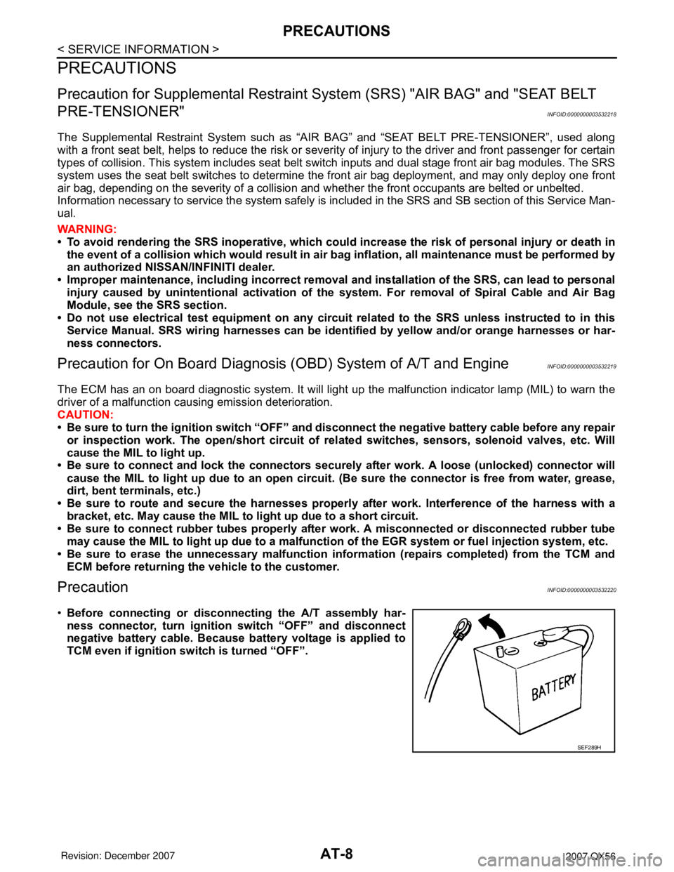
•Before connecting or disconnecting the A/T assembly har-
ness connector, turn ignition switch “OFF” and disconnect
negative battery cable. Because battery voltage is applied to
TCM even if ignition switch is turned “OFF”.
SEF289H
Page 571 of 3061
AUDIO
AV-31
< SERVICE INFORMATION >
C
D
E
F
G
H
I
J
L
MA
B
AV
N
O
P
• Loss of power to the satellite radio tuner (factory installed)
• Open or short in the REQ1, TXD, or RXD circuits.
If the satellite antenna is disconnected or inoperative, the display unit will display ANTENNA.
Noise InspectionINFOID:0000000003533674
The vehicle itself can be a source of noise if noise prevention parts or electrical equipment is malfunctioning.
Check if noise is caused and/or changed by engine speed, ignition switch turned to each position, and opera-
tion of each piece of electrical equipment, and determine the cause.
NOTE:
The source of the noise can be found easily by listening to the noise while removing the fuses of electrical
components, one by one.
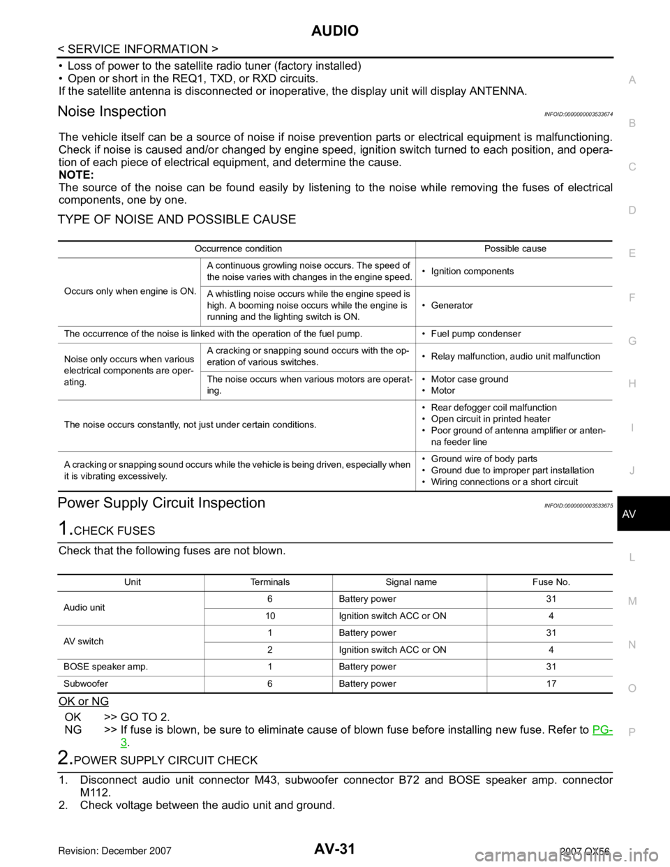
TYPE OF NOISE AND POSSIBLE CAUSE
Power Supply Circuit InspectionINFOID:0000000003533675
1.CHECK FUSES
Check that the following fuses are not blown.
OK or NG
OK >> GO TO 2.
NG >> If fuse is blown, be sure to eliminate cause of blown fuse before installing new fuse. Refer to PG-
3.
2.POWER SUPPLY CIRCUIT CHECK
1. Disconnect audio unit connector M43, subwoofer connector B72 and BOSE speaker amp. connector
M112.
2. Check voltage between the audio unit and ground.
Occurrence condition Possible cause
Occurs only when engine is ON.A continuous growling noise occurs. The speed of
the noise varies with changes in the engine speed.• Ignition components
A whistling noise occurs while the engine speed is
high. A booming noise occurs while the engine is
running and the lighting switch is ON.• Generator
The occurrence of the noise is linked with the operation of the fuel pump. • Fuel pump condenser
Noise only occurs when various
electrical components are oper-
ating.A cracking or snapping sound occurs with the op-
eration of various switches.• Relay malfunction, audio unit malfunction
The noise occurs when various motors are operat-
ing.• Motor case ground
•Motor
The noise occurs constantly, not just under certain conditions.• Rear defogger coil malfunction
• Open circuit in printed heater
• Poor ground of antenna amplifier or anten-
na feeder line
A cracking or snapping sound occurs while the vehicle is being driven, especially when
it is vibrating excessively.• Ground wire of body parts
• Ground due to improper part installation
• Wiring connections or a short circuit
Unit Terminals Signal name Fuse No.
Audio unit6 Battery power 31
10 Ignition switch ACC or ON 4
AV switch1 Battery power 31
2 Ignition switch ACC or ON 4
BOSE speaker amp. 1 Battery power 31
Subwoofer 6 Battery power 17
Page 1023 of 3061
DI-12
< SERVICE INFORMATION >
COMBINATION METERS
Self-Diagnosis Mode of Combination Meter
INFOID:0000000003533486
SELF-DIAGNOSIS FUNCTION
The following items can be checked during Combination Meter Self-Diagnosis Mode.
• Gauge sweep and present gauge values.
• Illuminates all odometer, fuel, and engine temperature segments.
• Illuminates all micro controlled lamps/LE D's regardless of switch configuration.
• Displays estimated present battery voltage.
• Displays seat belt buckle switch LH status.
HOW TO INITIATE COMBINATION METER SELF- DIAGNOSIS MODE
NOTE:
Once entered, Combination Meter Self-Diagnosis Mode will function with the ignition switch in ON or START.
Combination Meter Self-Diagnosis Mode will exit upon turning the ignition switch to OFF or ACC.
To initiate Combination Meter Self-Diagnosis Mode, refer to the following procedure.
1. Turn the ignition switch ON, while holding the odom eter/trip meter switch for 5 - 8 seconds. When the
diagnosis function is activated the odometer/trip meter will display tESt.
NOTE:
Check combination meter power supply and ground ci rcuit when self-diagnosis mode of combination
meter does not start. Refer to DI-16, "
Power Supply and Ground Circuit Inspection". Replace combination
meter if normal. Refer to IP-10, "
Removal and Installation".
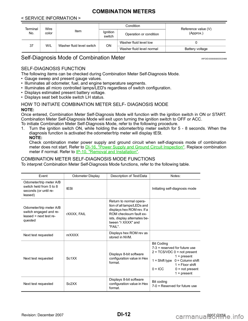
COMBINATION METER SELF-DIAGNOSIS MODE FUNCTIONS
To interpret Combination Meter Self-Diagnosis Mode functions, refer to the following table.
37 W/L Washer fluid level switch ON Washer fluid level low 0
Washer fluid level normal Battery voltage
Te r m i n a l
No. Wire
color Item Condition
Reference value (V)
(Approx.)
Ignition
switch Operation or condition
Event Odometer Display Description of Test/Data Notes:
Odometer/trip meter A/B
switch held from 5 to 8
seconds (or until re-
leased) tESt Initiating self-diagnosis mode
Odometer/trip meter A/B
switch engaged and re-
leased = next test re-
quested rXXXX, FAILReturn to normal opera-
tion of all lamps/LEDs and
displays hex ROM rev. If a
ROM checksum fault ex-
ists, display alternates be-
tween "r XXXX" and
"FAIL".
Next test requested nrXXXX Displays hex ROM rev as
stored in NVM.
Next test requested Sc1XX Displays 8-bit software
configuration value in Hex
format.Bit Coding
7-3 = reserved for future use
2 = TCS/VDC 0 = not present
1 = present
1 = Shift type 0 = Column shift
1 = Floor shift
0 = ICC 0 = not present
1 = present
Next test requested Sc2XX Displays 8-bit software
configuration value in Hex
format.Bit coding
7-0 = Reserved for future use
Page 1100 of 3061
PRECAUTIONS
EC-17
< SERVICE INFORMATION >
C
D
E
F
G
H
I
J
K
L
MA
EC
N
P O
PRECAUTIONS
Precaution for Supplemental Restraint System (SRS) "AIR BAG" and "SEAT BELT
PRE-TENSIONER"
INFOID:0000000003531580
The Supplemental Restraint System such as “AIR BAG” and “SEAT BELT PRE-TENSIONER”, used along
with a front seat belt, helps to reduce the risk or severity of injury to the driver and front passenger for certain
types of collision. This system includes seat belt switch inputs and dual stage front air bag modules. The SRS
system uses the seat belt switches to determine the front air bag deployment, and may only deploy one front
air bag, depending on the severity of a collision and whether the front occupants are belted or unbelted.
Information necessary to service the system safely is included in the SRS and SB section of this Service Man-
ual.
WARNING:
• To avoid rendering the SRS inoperative, which could increase the risk of personal injury or death in
the event of a collision which would result in air bag inflation, all maintenance must be performed by
an authorized NISSAN/INFINITI dealer.
• Improper maintenance, including incorrect removal and installation of the SRS, can lead to personal
injury caused by unintentional activation of the system. For removal of Spiral Cable and Air Bag
Module, see the SRS section.
• Do not use electrical test equipment on any circuit related to the SRS unless instructed to in this
Service Manual. SRS wiring harnesses can be identified by yellow and/or orange harnesses or har-
ness connectors.
On Board Diagnosis (OBD) System of Engine and A/TINFOID:0000000003531581
The ECM has an on board diagnostic system. It will light up the malfunction indicator lamp (MIL) to warn the
driver of a malfunction causing emission deterioration.
CAUTION:
• Be sure to turn the ignition switch OFF and disconnect the negative battery cable before any repair
or inspection work. The open/short circuit of related switches, sensors, solenoid valves, etc. will
cause the MIL to light up.
• Be sure to connect and lock the connectors securely after work. A loose (unlocked) connector will
cause the MIL to light up due to the open circuit. (Be sure the connector is free from water, grease,
dirt, bent terminals, etc.)
• Certain systems and components, especially those related to OBD, may use a new style slide-lock-
ing type harness connector. For description and how to disconnect, refer to PG-66
.
• Be sure to route and secure the harnesses properly after work. The interference of the harness with
a bracket, etc. may cause the MIL to light up due to the short circuit.
• Be sure to connect rubber tubes properly after work. A misconnected or disconnected rubber tube
may cause the MIL to light up due to the malfunction of the EVAP system or fuel injection system,
etc.
• Be sure to erase the unnecessary malfunction information (repairs completed) from the ECM and
TCM (Transmission control module) before returning the vehicle to the customer.
PrecautionINFOID:0000000003531582
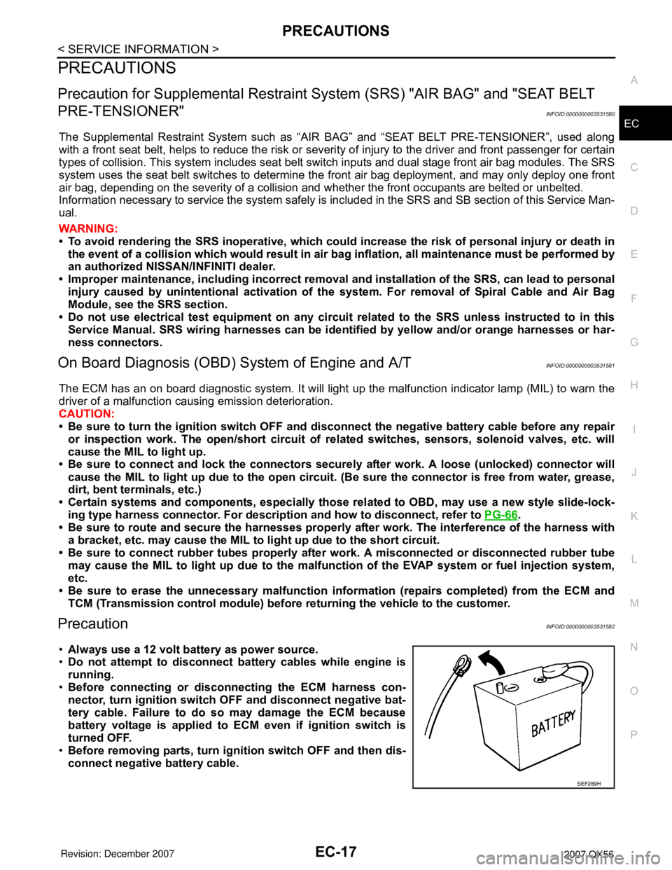
•Always use a 12 volt battery as power source.
•Do not attempt to disconnect battery cables while engine is
running.
•Before connecting or disconnecting the ECM harness con-
nector, turn ignition switch OFF and disconnect negative bat-
tery cable. Failure to do so may damage the ECM because
battery voltage is applied to ECM even if ignition switch is
turned OFF.
•Before removing parts, turn ignition switch OFF and then dis-
connect negative battery cable.
SEF289H
Page 1104 of 3061
PREPARATION
EC-21
< SERVICE INFORMATION >
C
D
E
F
G
H
I
J
K
L
MA
EC
N
P O
PREPARATION
Special Service ToolINFOID:0000000003531583
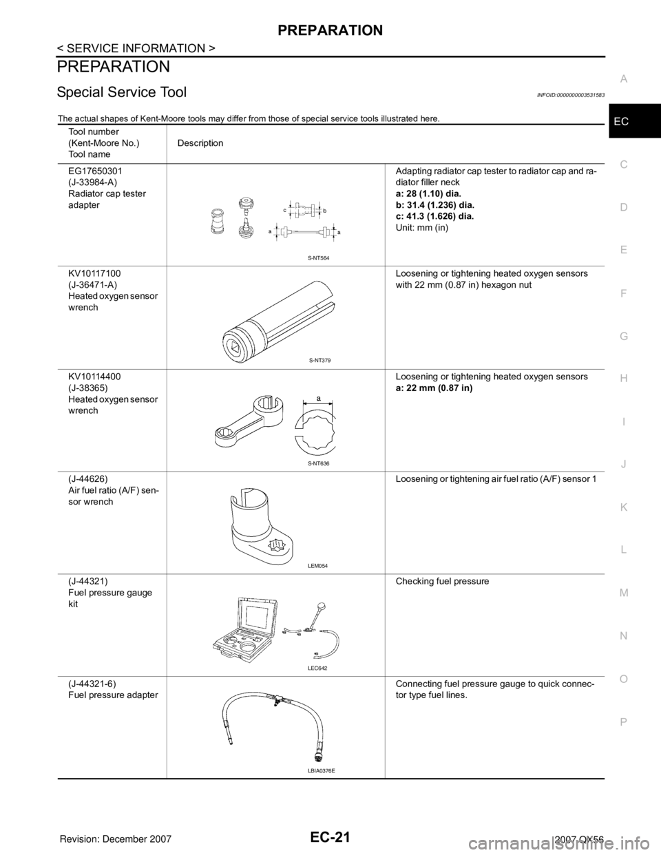
The actual shapes of Kent-Moore tools may differ from those of special service tools illustrated here.
Tool number
(Kent-Moore No.)
Tool nameDescription
EG17650301
(J-33984-A)
Radiator cap tester
adapterAdapting radiator cap tester to radiator cap and ra-
diator filler neck
a: 28 (1.10) dia.
b: 31.4 (1.236) dia.
c: 41.3 (1.626) dia.
Unit: mm (in)
KV10117100
(J-36471-A)
Heated oxygen sensor
wrenchLoosening or tightening heated oxygen sensors
with 22 mm (0.87 in) hexagon nut
KV10114400
(J-38365)
Heated oxygen sensor
wrenchLoosening or tightening heated oxygen sensors
a: 22 mm (0.87 in)
(J-44626)
Air fuel ratio (A/F) sen-
sor wrenchLoosening or tightening air fuel ratio (A/F) sensor 1
(J-44321)
Fuel pressure gauge
kitChecking fuel pressure
(J-44321-6)
Fuel pressure adapterConnecting fuel pressure gauge to quick connec-
tor type fuel lines.
S-NT564
S-NT379
S-NT636
LEM054
LEC642
LBIA0376E
Page 1109 of 3061
EC-26
< SERVICE INFORMATION >
ENGINE CONTROL SYSTEM
The mixture ratio feedback system provides the best air-fuel mixture ratio for driveability and emission control.
The three way catalyst (manifold) can then better reduce CO, HC and NOx emissions. This system uses air
fuel ratio (A/F) sensor 1 in the exhaust manifold to monitor whether the engine operation is rich or lean. The
ECM adjusts the injection pulse width according to the sensor voltage signal. For more information about air
fuel ratio (A/F) sensor 1, refer to EC-225
. This maintains the mixture ratio within the range of stoichiometric
(ideal air-fuel mixture).
This stage is referred to as the closed loop control condition.
Heated oxygen sensor 2 is located downstream of the three way catalyst (manifold). Even if the switching
characteristics of air fuel ratio (A/F) sensor 1 shift, the air-fuel ratio is controlled to stoichiometric by the signal
from heated oxygen sensor 2.
Open Loop Control
The open loop system condition refers to when the ECM detects any of the following conditions. Feedback
control stops in order to maintain stabilized fuel combustion.
• Deceleration and acceleration
• High-load, high-speed operation
• Malfunction of A/F sensor 1 or its circuit
• Insufficient activation of A/F sensor 1 at low engine coolant temperature
• High engine coolant temperature
• During warm-up
• After shifting from N to D
• When starting the engine
MIXTURE RATIO SELF-LEARNING CONTROL
The mixture ratio feedback control system monitors the mixture ratio signal transmitted from A/F sensor 1.
This feedback signal is then sent to the ECM. The ECM controls the basic mixture ratio as close to the theoret-
ical mixture ratio as possible. However, the basic mixture ratio is not necessarily controlled as originally
designed. Both manufacturing differences (i.e., mass air flow sensor hot wire) and characteristic changes dur-
ing operation (i.e., injector clogging) directly affect mixture ratio.
Accordingly, the difference between the basic and theoretical mixture ratios is monitored in this system. This is
then computed in terms of “injection pulse duration” to automatically compensate for the difference between
the two ratios.
“Fuel trim” refers to the feedback compensation value compared against the basic injection duration. Fuel trim
includes short term fuel trim and long term fuel trim.
“Short term fuel trim” is the short-term fuel compensation used to maintain the mixture ratio at its theoretical
value. The signal from A/F sensor 1 indicates whether the mixture ratio is RICH or LEAN compared to the the-
oretical value. The signal then triggers a reduction in fuel volume if the mixture ratio is rich, and an increase in
fuel volume if it is lean.
“Long term fuel trim” is overall fuel compensation carried out long-term to compensate for continual deviation
of the short term fuel trim from the central value. Such deviation will occur due to individual engine differences,
wear over time and changes in the usage environment.
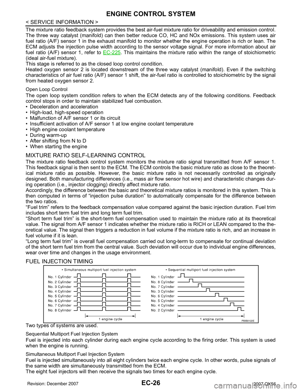
FUEL INJECTION TIMING
Two types of systems are used.
Sequential Multiport Fuel Injection System
Fuel is injected into each cylinder during each engine cycle according to the firing order. This system is used
when the engine is running.
Simultaneous Multiport Fuel Injection System
Fuel is injected simultaneously into all eight cylinders twice each engine cycle. In other words, pulse signals of
the same width are simultaneously transmitted from the ECM.
The eight fuel injectors will then receive the signals two times for each engine cycle.
PBIB0122E
Page 1436 of 3061
DTC P0420, P0430 THREE WAY CATALYST FUNCTION
EC-353
< SERVICE INFORMATION >
C
D
E
F
G
H
I
J
K
L
MA
EC
N
P O
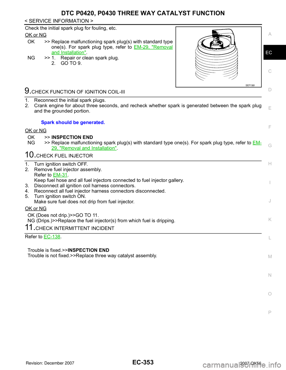
Check the initial spark plug for fouling, etc.
OK or NG
OK >> Replace malfunctioning spark plug(s) with standard type
one(s). For spark plug type, refer to EM-29, "
Removal
and Installation".
NG >> 1. Repair or clean spark plug.
2. GO TO 9.
9.CHECK FUNCTION OF IGNITION COIL-III
1. Reconnect the initial spark plugs.
2. Crank engine for about three seconds, and recheck whether spark is generated between the spark plug
and the grounded portion.
OK or NG
OK >>INSPECTION END
NG >> Replace malfunctioning spark plug(s) with standard type one(s). For spark plug type, refer to EM-
29, "Removal and Installation".
10.CHECK FUEL INJECTOR
1. Turn ignition switch OFF.
2. Remove fuel injector assembly.
Refer to EM-31
.
Keep fuel hose and all fuel injectors connected to fuel injector gallery.
3. Disconnect all ignition coil harness connectors.
4. Reconnect all fuel injector harness connectors disconnected.
5. Turn ignition switch ON.
Make sure fuel does not drip from fuel injector.
OK or NG
OK (Does not drip.)>>GO TO 11.
NG (Drips.)>>Replace the fuel injector(s) from which fuel is dripping.
11 .CHECK INTERMITTENT INCIDENT
Refer to EC-138
.
Trouble is fixed.>>INSPECTION END
Trouble is not fixed.>>Replace three way catalyst assembly.
SEF156I
Spark should be generated.
Page 1696 of 3061
FUEL PUMP
EC-613
< SERVICE INFORMATION >
C
D
E
F
G
H
I
J
K
L
MA
EC
N
P O
FUEL PUMP
DescriptionINFOID:0000000003532166
SYSTEM DESCRIPTION
*: ECM determines the start signal status by the signals of engine speed and battery voltage.
The ECM activates the fuel pump for several seconds after the ignition switch is turned ON to improve engine
startability. If the ECM receives a engine speed signal from the camshaft position sensor (PHASE), it knows
that the engine is rotating, and causes the pump to operate. If the engine speed signal is not received when
the ignition switch is ON, the engine stalls. The ECM stops pump operation and prevents battery discharging,
thereby improving safety. The ECM does not directly drive the fuel pump. It controls the ON/OFF fuel pump
relay, which in turn controls the fuel pump.
COMPONENT DESCRIPTION
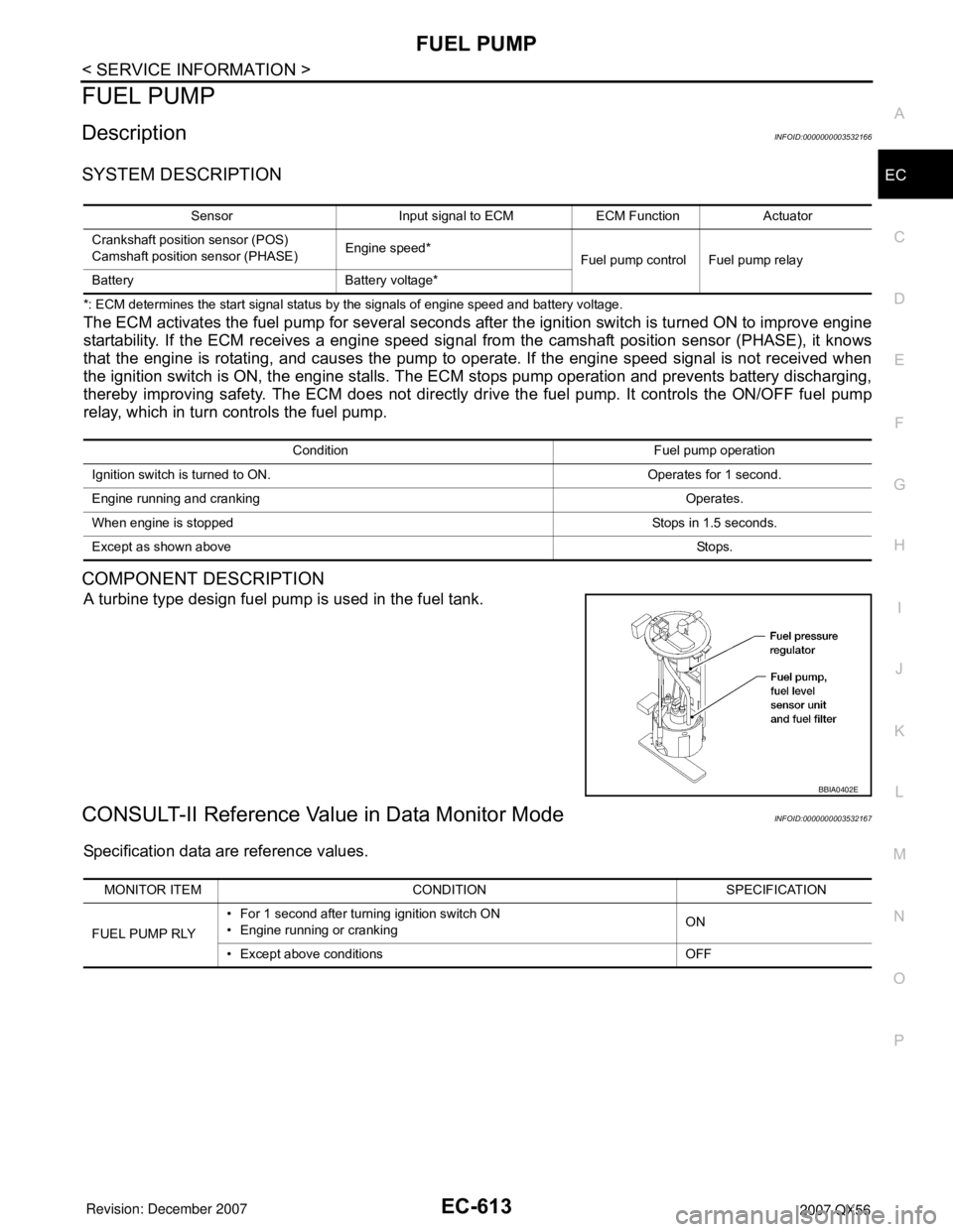
A turbine type design fuel pump is used in the fuel tank.
CONSULT-II Reference Value in Data Monitor ModeINFOID:0000000003532167
Specification data are reference values.
Sensor Input signal to ECM ECM Function Actuator
Crankshaft position sensor (POS)
Camshaft position sensor (PHASE)Engine speed*
Fuel pump control Fuel pump relay
Battery Battery voltage*
Condition Fuel pump operation
Ignition switch is turned to ON. Operates for 1 second.
Engine running and crankingOperates.
When engine is stopped Stops in 1.5 seconds.
Except as shown aboveSto ps .
BBIA0402E
MONITOR ITEM CONDITION SPECIFICATION
FUEL PUMP RLY• For 1 second after turning ignition switch ON
• Engine running or crankingON
• Except above conditions OFF
Page 1771 of 3061

EM-1
ENGINE
C
DE
F
G H
I
J
K L
M
SECTION EM
A
EM
N
O P
CONTENTS
ENGINE MECHANICAL
SERVICE INFORMATION .. ..........................3
PRECAUTIONS .............................................. .....3
Precaution for Supplemental Restraint System
(SRS) "AIR BAG" and "SEAT BELT PRE-TEN-
SIONER" ............................................................. ......
3
Precaution for Drain Engine Coolant .........................3
Precaution for Disconnecting Fuel Piping .................3
Precaution for Removal and Disassembly ................3
Precaution for Inspection, Repair and Replace-
ment .................................................................... ......
3
Precaution for Assembly and Installation ..................3
Parts Requiring Angular Tightening ..........................4
Precaution for Liquid Gasket ............................... ......4
PREPARATION ...................................................6
Special Service Tool ........................................... ......6
Commercial Service Tool ..........................................8
NOISE, VIBRATION AND HARSHNESS
(NVH) TROUBLESHOOTING ............................
10
NVH Troubleshooting - Engine Noise ................. ....10
Use the Chart Below to Help You Find the Cause
of the Symptom .......................................................
11
ENGINE ROOM COVER ....................................12
Removal and Installation .........................................12
DRIVE BELTS ................................................ ....13
Checking Drive Belts ........................................... ....13
Removal and Installation .........................................13
Drive Belt Auto Tensioner and Idler Pulley ......... ....14
AIR CLEANER AND AIR DUCT ........................15
Removal and Installation .........................................15
Removal and Installation (Viscous paper type) ... ....15
INTAKE MANIFOLD ...........................................17
Removal and Installation .........................................17
EXHAUST MANIFOLD AND THREE WAY
CATALYST ..................................................... ....
21
Removal and Installation ..................................... ....21
OIL PAN AND OIL STRAINER .........................24
Removal and Installation .........................................24
IGNITION COIL .................................................28
Removal and Installation .........................................28
SPARK PLUG ...................................................29
Removal and Installation .........................................29
FUEL INJECTOR AND FUEL TUBE ................31
Removal and Installation .........................................31
ROCKER COVER .............................................35
Removal and Installation .........................................35
TIMING CHAIN ..................................................37
Exploded View ..................................................... ....37
Removal and Installation .........................................38
CAMSHAFT .......................................................46
Removal and Installation .........................................46
Inspection after Installation ......................................55
Valve Clearance .................................................. ....56
OIL SEAL ..........................................................61
Removal and Installation of Valve Oil Seal ..............61
Removal and Installation of Front Oil Seal ..............61
Removal and Installation of Rear Oil Seal ...............62
CYLINDER HEAD .............................................64
On-Vehicle Service .............................................. ....64
Removal and Installation .........................................65
Disassembly and Assembly .....................................67
Inspection After Disassembly ..................................69
ENGINE ASSEMBLY ........................................74
Removal and Installation ..................................... ....74
CYLINDER BLOCK ...........................................78
Disassembly and Assembly .....................................78
How to Select Piston and Bearing ....................... ....86