belt INFINITI QX56 2007 Factory Owner's Guide
[x] Cancel search | Manufacturer: INFINITI, Model Year: 2007, Model line: QX56, Model: INFINITI QX56 2007Pages: 3061, PDF Size: 64.56 MB
Page 999 of 3061

CO-10
< SERVICE INFORMATION >
ENGINE COOLANT
• Wrap a thick cloth around the cap to carefully remove the cap. First, turn the cap a quarter of a turn
to release any built-up pressure, then push down and turn the cap all the way to remove it.
DRAINING ENGINE COOLANT
1. Turn ignition switch ON and set temperature control lever all the way to HOT position or the highest tem-
perature position. Wait 10 seconds and turn ignition switch OFF.
2. Remove the engine front undercover using power tool.
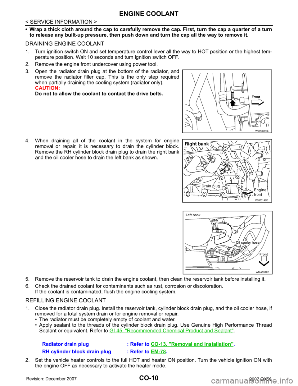
3. Open the radiator drain plug at the bottom of the radiator, and
remove the radiator filler cap. This is the only step required
when partially draining the cooling system (radiator only).
CAUTION:
Do not to allow the coolant to contact the drive belts.
4. When draining all of the coolant in the system for engine
removal or repair, it is necessary to drain the cylinder block.
Remove the RH cylinder block drain plug to drain the right bank
and the oil cooler hose to drain the left bank as shown.
5. Remove the reservoir tank to drain the engine coolant, then clean the reservoir tank before installing it.
6. Check the drained coolant for contaminants such as rust, corrosion or discoloration.
If the coolant is contaminated, flush the engine cooling system.
REFILLING ENGINE COOLANT
1. Close the radiator drain plug. Install the reservoir tank, cylinder block drain plug, and the oil cooler hose, if
removed for a total system drain or for engine removal or repair.
• The radiator must be completely empty of coolant and water.
• Apply sealant to the threads of the cylinder block drain plug. Use Genuine High Performance Thread
Sealant or equivalent. Refer to GI-45, "
Recommended Chemical Product and Sealant".
2. Set the vehicle heater controls to the full HOT and heater ON position. Turn the vehicle ignition ON with
the engine OFF as necessary to activate the heater mode.
WBIA0391E
PBIC0146E
WBIA0392E
Radiator drain plug : Refer to CO-13, "Removal and Installation".
RH cylinder block drain plug : Refer to EM-78
.
Page 1002 of 3061

RADIATOR
CO-13
< SERVICE INFORMATION >
C
D
E
F
G
H
I
J
K
L
MA
CO
N
P O
RADIATOR
Removal and InstallationINFOID:0000000003531571
WARNING:
Never remove the radiator cap when the engine is hot. Serious burns could occur from high-pressure
engine coolant escaping from the radiator.
REMOVAL
CAUTION:
Perform when the engine is cold.
1. Remove engine room cover. Refer to EM-12, "
Removal and Installation".
2. Drain engine coolant from the radiator. Refer to CO-9, "
Changing Engine Coolant".
3. Remove air cleaner and air duct assembly. Refer to EM-15, "
Removal and Installation".
4. Disconnect A/T fluid cooler hoses.
• Install blind plug to avoid leakage of A/T fluid.
5. Disconnect radiator upper and lower hoses from radiator.
CAUTION:
Do not allow coolant to contact drive belts.
WBIA0694E
1. Radiator 2. Bolt 3. Mounting rubber
4. A/T fluid cooler hose 5. Radiator hose (lower) 6. Air guides
7. Radiator shroud (upper) 8. Radiator shroud (lower) 9. Drain plug
10. Radiator hose (upper) 11. Reservoir tank hose 12. By-pass hose
13. Reservoir tank 14. Reservoir tank cap A. To radiator fill neck
B. To A/T cooler tube C. To water suction pipe D. To thermostat housing
Page 1005 of 3061

CO-16
< SERVICE INFORMATION >
ENGINE COOLING FAN
ENGINE COOLING FAN
Removal and Installation (Crankshaft Driven Type)INFOID:0000000003531573
REMOVAL
1. Remove the air duct and resonator assembly. Refer to EM-15, "Removal and Installation".
2. Remove the engine front undercover using power tool.
3. Remove the lower radiator shroud. Refer to CO-13, "
Removal and Installation".
4. Remove the drive belt. Refer to EM-13, "
Removal and Installation".
5. Remove the cooling fan.
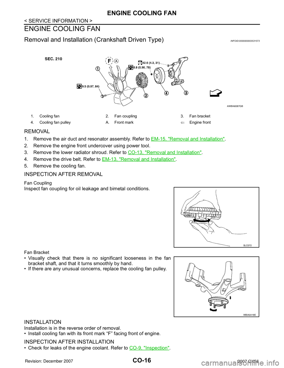
INSPECTION AFTER REMOVAL
Fan Coupling
Inspect fan coupling for oil leakage and bimetal conditions.
Fan Bracket
• Visually check that there is no significant looseness in the fan
bracket shaft, and that it turns smoothly by hand.
• If there are any unusual concerns, replace the cooling fan pulley.
INSTALLATION
Installation is in the reverse order of removal.
• Install cooling fan with its front mark “F” facing front of engine.
INSPECTION AFTER INSTALLATION
• Check for leaks of the engine coolant. Refer to CO-9, "Inspection".
1. Cooling fan 2. Fan coupling 3. Fan bracket
4. Cooling fan pulley A. Front mark⇐Engine front
AWBIA0087GB
SLC072
WBIA0418E
Page 1007 of 3061

CO-18
< SERVICE INFORMATION >
WATER PUMP
WATER PUMP
Removal and InstallationINFOID:0000000003531575
CAUTION:
• When removing water pump, be careful not to get engine coolant on drive belt.
• Water pump cannot be disassembled and should be replaced as a unit.
REMOVAL
1. Drain engine coolant so that no engine coolant comes out from water pump fitting hole. Refer to CO-9,
"Changing Engine Coolant".
CAUTION:
Perform when the engine is cold.
2. Remove the engine front undercover using power tool.
3. Remove the air duct and resonator assembly. Refer to EM-15, "
Removal and Installation".
4. Remove the drive belt. Refer to EM-13, "
Removal and Installation".
5. Remove the water pump pulley.
6. Remove the water pump.
• Engine coolant will leak from the cylinder block, so have a receptacle ready below.
CAUTION:
Handle water pump vane so that it does not contact any other parts.
INSPECTION AFTER REMOVAL
• Visually check that there is no significant dirt or rust on the water
pump body and vane.
• Make sure there is no looseness in the vane shaft, and that it turns
smoothly when rotated by hand.
• Replace the water pump, if necessary.
INSTALLATION
Installation is in the reverse order of removal.
• After installation bleed the air from the cooling system. Refer to CO-9, "
Changing Engine Coolant".
INSPECTION AFTER INSTALLATION
KBIA2543E
1. Gasket 2. Water pump 3. Water pump pulley
KBIA2552E
Page 1012 of 3061

DI-1
ELECTRICAL
C
DE
F
G H
I
J
L
M
SECTION DI
A
B
DI
N
O P
CONTENTS
DRIVER INFORMATION SYSTEM
SERVICE INFORMATION .. ..........................3
PRECAUTION ................................................ .....3
Precaution for Supplemental Restraint System
(SRS) "AIR BAG" and "SEAT BELT PRE-TEN-
SIONER" ............................................................. ......
3
PREPARATION ...................................................4
Commercial Service Tool .................................... ......4
COMBINATION METERS ...................................5
Component Parts and Harness Connector Loca-
tion ...................................................................... ......
5
System Description ...................................................5
Arrangement of Combination Meter ..........................7
Internal Circuit ...........................................................8
Wiring Diagram - METER - .......................................9
Combination Meter Harness Connector Terminal
Layout .....................................................................
11
Terminal and Reference Value for Combination
Meter .......................................................................
11
Self-Diagnosis Mode of Combination Meter ........ ....12
How to Proceed with Trouble Diagnosis ............. ....15
Preliminary Check ...................................................15
Symptom Chart .......................................................16
Power Supply and Ground Circuit Inspection .........16
Vehicle Speed Signal Inspection .............................17
Engine Oil Pressure Signal Inspection ....................17
Water Temperature Signal Inspection .....................18
Engine Speed Signal Inspection ......................... ....18
Fuel Level Sensor Unit Inspection ...................... ....18
Fuel Gauge Fluctuates, Indicates Wrong Value, or
Varies .................................................................. ....
20
Fuel Gauge Does Not Move to Full-position ...........20
Electrical Component Inspection ......................... ....21
Removal and Installation of Combination Meter .....21
COMPASS AND THERMOMETER ................ ....22
System Description ............................................. ....22
Wiring Diagram - COMPAS - ..................................23
Trouble Diagnosis ............................................... ....23
Calibration Procedure for Compass .................... ....24
WARNING LAMPS ............................................26
Schematic ............................................................ ....26
Wiring Diagram - WARN - .......................................27
Oil Pressure Warning Lamp Stays Off (Ignition
Switch ON) .......................................................... ....
32
Oil Pressure Warning Lamp Does Not Turn Off
(Oil Pressure Is Normal) ...................................... ....
33
A/T INDICATOR ................................................34
Wiring Diagram - AT/IND - .......................................34
A/T Indicator Does Not Illuminate ............................34
WARNING CHIME .............................................36
Component Parts and Harness Connector Loca-
tion ....................................................................... ....
36
System Description ..................................................36
CAN Communication System Description ...............37
Wiring Diagram - CHIME - .......................................38
Terminal and Reference Value for BCM ..................39
Terminal and Reference Value for Combination
Meter ................................................................... ....
39
How to Proceed with Trouble Diagnosis ..................40
Preliminary Check ............................................... ....40
CONSULT-II Function (BCM) ..................................40
All Warning Chimes Do Not Operate .......................41
Key Warning Chime and Light Warning Chime Do
Not Operate (Seat Belt Warning Chime Does Op-
erate) .......................................................................
41
Key Warning Chime Does Not Operate ...................42
Light Warning Chime Does Not Operate .................44
Seat Belt Warning Chime Does Not Operate ..........44
REAR SONAR SYSTEM ...................................46
Component Parts and Harness Connector Loca-
tion ....................................................................... ....
46
System Description ..................................................46
Wiring Diagram - SONAR - ......................................48
Sonar Control Unit Harness Connector Terminal
Layout ......................................................................
50
Page 1014 of 3061

PRECAUTIONDI-3
< SERVICE INFORMATION >
C
DE
F
G H
I
J
L
M A
B
DI
N
O P
SERVICE INFORMATION
PRECAUTION
Precaution for Supplemental Restraint System (SRS) "AIR BAG" and "SEAT BELT
PRE-TENSIONER"
INFOID:0000000003533477
The Supplemental Restraint System such as “A IR BAG” and “SEAT BELT PRE-TENSIONER”, used along
with a front seat belt, helps to reduce the risk or severi ty of injury to the driver and front passenger for certain
types of collision. This system includes seat belt switch inputs and dual stage front air bag modules. The SRS
system uses the seat belt switches to determine the front air bag deployment, and may only deploy one front
air bag, depending on the severity of a collision and w hether the front occupants are belted or unbelted.
Information necessary to service the system safely is included in the SRS and SB section of this Service Man-
ual.
WARNING:
• To avoid rendering the SRS inoper ative, which could increase the risk of personal injury or death in
the event of a collision which would result in air bag inflation, all maintenance must be performed by
an authorized NISSAN/INFINITI dealer.
• Improper maintenance, including in correct removal and installation of the SRS, can lead to personal
injury caused by unintentional act ivation of the system. For removal of Spiral Cable and Air Bag
Module, see the SRS section.
• Do not use electrical test equipm ent on any circuit related to the SRS unless instructed to in this
Service Manual. SRS wiring harnesses can be identi fied by yellow and/or orange harnesses or har-
ness connectors.
Page 1022 of 3061

COMBINATION METERSDI-11
< SERVICE INFORMATION >
C
DE
F
G H
I
J
L
M A
B
DI
N
O P
Combination Meter Harness Connector Terminal LayoutINFOID:0000000003533484
Terminal and Reference Va lue for Combination MeterINFOID:0000000003533485
LKIA0698E
Te r m i n a l
No. Wire
color Item Condition
Reference value (V)
(Approx.)
Ignition
switch Operation or condition
1 O Ignition switch ACC or ON ON — Battery voltage
8 Y/R Battery power supply OFF — Battery voltage
9 R/G Stop lamp switch ON Brake pedal depressed Battery voltage
Brake pedal released 0
10 P/B Brake fluid level switch ON Brake fluid level low 0
Brake fluid level normal Battery voltage
11 L C A N - H — — —
12 P CAN-L — — —
14 P/L Seat belt buckle switch
RH ONUnfastened (ON) 0
Fastened (OFF) Battery voltage
15 Y/L Fuel level sensor signal — — Refer to
DI-18, "
Fuel Level Sensor
Unit Inspection".
16 B/P Fuel level sensor and oil
pressure sensor ground ON — 0V
17 B Ground — — 0V
18 BR Illumination control switch — Lighting switch ON Refer to
LT- 1 2 0 , "
System Descrip-
tion".
23 G Parking Brake switch ON Parking brake applied 0
Parking brake released Battery voltage
24 O/L Ignition switch ON or
START ON — Battery voltage
27 O/B Seat belt buckle pre-ten-
sioner assembly LH (seat
belt buckle switch) ON
Unfastened (ON) 0
Fastened (OFF) Battery voltage
28 G/O Security indicator input OFF Security indicator ON 0
Security indicator
OFF Battery voltage
29 W/R Vehicle speed signal
(8-pulse) ONSpeedometer operated
[When vehicle speed is ap-
prox. 40 km/h (25 MPH)]
PKIA1935E
Page 1023 of 3061

DI-12
< SERVICE INFORMATION >
COMBINATION METERS
Self-Diagnosis Mode of Combination Meter
INFOID:0000000003533486
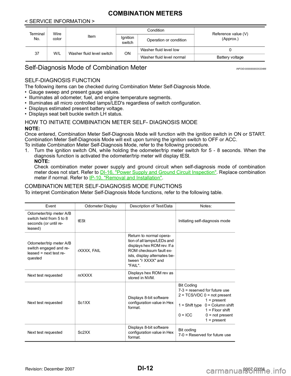
SELF-DIAGNOSIS FUNCTION
The following items can be checked during Combination Meter Self-Diagnosis Mode.
• Gauge sweep and present gauge values.
• Illuminates all odometer, fuel, and engine temperature segments.
• Illuminates all micro controlled lamps/LE D's regardless of switch configuration.
• Displays estimated present battery voltage.
• Displays seat belt buckle switch LH status.
HOW TO INITIATE COMBINATION METER SELF- DIAGNOSIS MODE
NOTE:
Once entered, Combination Meter Self-Diagnosis Mode will function with the ignition switch in ON or START.
Combination Meter Self-Diagnosis Mode will exit upon turning the ignition switch to OFF or ACC.
To initiate Combination Meter Self-Diagnosis Mode, refer to the following procedure.
1. Turn the ignition switch ON, while holding the odom eter/trip meter switch for 5 - 8 seconds. When the
diagnosis function is activated the odometer/trip meter will display tESt.
NOTE:
Check combination meter power supply and ground ci rcuit when self-diagnosis mode of combination
meter does not start. Refer to DI-16, "
Power Supply and Ground Circuit Inspection". Replace combination
meter if normal. Refer to IP-10, "
Removal and Installation".
COMBINATION METER SELF-DIAGNOSIS MODE FUNCTIONS
To interpret Combination Meter Self-Diagnosis Mode functions, refer to the following table.
37 W/L Washer fluid level switch ON Washer fluid level low 0
Washer fluid level normal Battery voltage
Te r m i n a l
No. Wire
color Item Condition
Reference value (V)
(Approx.)
Ignition
switch Operation or condition
Event Odometer Display Description of Test/Data Notes:
Odometer/trip meter A/B
switch held from 5 to 8
seconds (or until re-
leased) tESt Initiating self-diagnosis mode
Odometer/trip meter A/B
switch engaged and re-
leased = next test re-
quested rXXXX, FAILReturn to normal opera-
tion of all lamps/LEDs and
displays hex ROM rev. If a
ROM checksum fault ex-
ists, display alternates be-
tween "r XXXX" and
"FAIL".
Next test requested nrXXXX Displays hex ROM rev as
stored in NVM.
Next test requested Sc1XX Displays 8-bit software
configuration value in Hex
format.Bit Coding
7-3 = reserved for future use
2 = TCS/VDC 0 = not present
1 = present
1 = Shift type 0 = Column shift
1 = Floor shift
0 = ICC 0 = not present
1 = present
Next test requested Sc2XX Displays 8-bit software
configuration value in Hex
format.Bit coding
7-0 = Reserved for future use
Page 1025 of 3061

DI-14
< SERVICE INFORMATION >
COMBINATION METERS
Next test requested ot0XXDisplays oil pressure tell-
tale "off" threshold in A/D
counts in Hex format.$00 - $FF
Next test requested XXXXX Raw uncompensated en-
glish speed value in hun-
dredths of MPH.
Speedometer indicates
present speed.Will display "-----"
if message is
not received. Will display
"99999" if data received is in-
valid
Next test requested XXXXX Raw uncompensated
metric speed value in hun-
dredths of KPH. Speed-
ometer indicates present
speed.Will display "-----"
if message is
not received. Will display
"99999" if data received is in-
valid
Next test requested tXXXX Tachometer value in
RPM. Tachometer indi-
cates present RPM.Will display "-----"
if message is
not received.
Next test requested F1 XXXX Present ratioed fuel level
A/D input 1 in decimal for-
mat. Fuel gauge indicates
present filtered level.000-009 = Short circuit
010-254 = Normal range
255 = Open circuit
--- = Missing 5 seconds
Next test requested F2 XXX Present FLPS. 010-254 normal range
Next test requested FS X Fuel filter rate 0 = Normal
1 = Fast
Next test requested XXXC Last temperature gauge
input value in degrees C.
Temperature gauge indi-
cates present filtered tem-
perature.Will display "---"
C if message is
not received.
Will display "999" if data re-
ceived is invalid.
Next test requested BAtXX.X Estimated present battery
voltage.
Next test requested rES -X Seat belt buckle switch LH
status.0 = Unbuckled
1 = Buckled
Next test requested PA -XX Hex value port A.
Next test requested Pb -XX Hex value port B.
Next test requested PE -XX Hex value port E.
Next test requested PL -XX Hex value port L.
Next test requested P6 -XX Hex value port K.
Next test requested Pn -XX Hex value port M.
Next test requested PP -XX Hex value port P.
Next test requested PS -XX Hex value port S.
Next test requested Pt -XX Hex value port T.
Next test requested Pu -XX Hex value port U.
Next test requested P4 -XX Hex value port V.
Next test requested Puu -XX Hex value port W.
Next test requested A00XXX A/D port A/D value (non-
ratioed).0-255
Next test requested A01XXX A/D port A/D value (non-
ratioed).
0-255
Next test requested A02XXX A/D port A/D value (non-
ratioed).0-255
Next test requested A03XXX A/D port A/D value (non-
ratioed).0-255
Event Odometer Display Description of Test/Data Notes:
Page 1047 of 3061

DI-36
< SERVICE INFORMATION >
WARNING CHIME
WARNING CHIME
Component Parts and Harness Connector LocationINFOID:0000000003533510
System DescriptionINFOID:0000000003533511
FUNCTION
Power is supplied at all times
• through 50A fusible link (letter f, located in the fuse and fusible link box)
• to BCM terminal 70,
• through 10A fuse [No. 19, located in the fuse block (J/B)]
1. Fuse block (J/B) 2. Fuse and fusible link box 3. Fuse and relay box
4. Combination meter M24 5. Combination switch (lighting switch)
M286. BCM M18, M19, M20 (view with in-
strument lower panel LH removed)
7. Front door switch LH B8 8. Key switch and key lock solenoid
M279. Seat belt buckle pre-tensioner as-
sembly LH (seat belt buckle switch)
B74
WKIA4594E