power steering INFINITI QX56 2007 Factory Repair Manual
[x] Cancel search | Manufacturer: INFINITI, Model Year: 2007, Model line: QX56, Model: INFINITI QX56 2007Pages: 3061, PDF Size: 64.56 MB
Page 2125 of 3061

INSTRUMENT PANEL ASSEMBLY
IP-13
< SERVICE INFORMATION >
C
D
E
F
G
H
J
K
L
MA
B
IP
N
O
P
INSTRUMENT LOWER COVER LH
Removal
1. Remove instrument lower cover LH, using power tool.
2. Pull to disconnect instrument lower cover LH clips.
3. Disconnect instrument lower cover LH electrical connectors.
Installation
Installation is in the reverse order of removal.
COMBINATION METER
Removal
1. Disconnect battery negative terminal.
2. Remove instrument lower cover LH. Refer to IP-10
.
3. Remove steering column cover upper and steering column
cover lower.
4. Remove combination meter cover.
5. Remove cluster lid A.
6. Disconnect cluster lid A electrical connectors.
7. Remove the combination meter screws, using power tool.
8. Disconnect combination meter electrical connectors.
Installation
Installation is in the reverse order of removal.
A/T FINISHER
Removal
1. Remove shift knob.
2. Remove storage compartment mask.
3. Pull to disconnect AT finisher clips.
4. Disconnect A/T finisher electrical connectors.
Installation
Installation is in the reverse order of removal.
LOWER INSTRUMENT PANEL RH AND GLOVE BOX
Removal
LIIA1327E
LIIA1249E
LIIA1335E
Page 2203 of 3061
![INFINITI QX56 2007 Factory Repair Manual LAN-72
< SERVICE INFORMATION >[CAN]
TROUBLE DIAGNOSIS
2.CHECK HARNESS FOR OPEN CIRCUIT
1. Disconnect the connector of front air control.
2. Check the resistance between the front air control harness c](/img/42/57029/w960_57029-2202.png "INFINITI QX56 2007 Factory Repair Manual LAN-72
< SERVICE INFORMATION >[CAN]
TROUBLE DIAGNOSIS
2.CHECK HARNESS FOR OPEN CIRCUIT
1. Disconnect the connector of front air control.
2. Check the resistance between the front air control harness c")
LAN-72
< SERVICE INFORMATION >[CAN]
TROUBLE DIAGNOSIS
2.CHECK HARNESS FOR OPEN CIRCUIT
1. Disconnect the connector of front air control.
2. Check the resistance between the front air control harness connector terminals.
OK or NG
OK >> GO TO 3.
NG >> Repair the front air control branch line.
3.CHECK POWER SUPPLY AND GROUND CIRCUIT
Check the power supply and the ground circuit of the front air control. Refer to ATC-36, "
Schematic".
OK or NG
OK >> • Present error: Replace the front air control. Refer to ATC-123, "Removal and Installation".
• Past error: Error was detected in the front air control branch line.
NG >> Repair the power supply and the ground circuit.
Combination Meter Branch Line CircuitINFOID:0000000003533655
INSPECTION PROCEDURE
1.CHECK CONNECTOR
1. Turn the ignition switch OFF.
2. Disconnect the battery cable from the negative terminal.
3. Check the terminals and connectors of the combination meter for damage, bend and loose connection
(unit side and connector side).
OK or NG
OK >> GO TO 2.
NG >> Repair the terminal and connector.
2.CHECK HARNESS FOR OPEN CIRCUIT
1. Disconnect the connector of combination meter.
2. Check the resistance between the combination meter harness connector terminals.
OK or NG
OK >> GO TO 3.
NG >> Repair the combination meter branch line.
3.CHECK POWER SUPPLY AND GROUND CIRCUIT
Check the power supply and the ground circuit of the combination meter. Refer to DI-9, "
Wiring Diagram -
METER -".
OK or NG
OK >> • Present error: Replace the combination meter. Refer to IP-10, "Removal and Installation".
• Past error: Error was detected in the combination meter branch line.
NG >> Repair the power supply and the ground circuit.
Steering Angle Sensor Branch Line CircuitINFOID:0000000003533656
INSPECTION PROCEDURE
1.CHECK CONNECTOR
1. Turn the ignition switch OFF.
Front air control harness connector
Resistance (Ω)
Connector No. Terminal No.
M50 34 35 Approx. 54 – 66
Combination meter harness connector
Resistance (Ω)
Connector No. Terminal No.
M24 11 12 Approx. 54 – 66
Page 2204 of 3061
![INFINITI QX56 2007 Factory Repair Manual TROUBLE DIAGNOSIS
LAN-73
< SERVICE INFORMATION >[CAN]
C
D
E
F
G
H
I
J
L
MA
B
LAN
N
O
P
2. Disconnect the battery cable from the negative terminal.
3. Check the terminals and connectors of the steering](/img/42/57029/w960_57029-2203.png "INFINITI QX56 2007 Factory Repair Manual TROUBLE DIAGNOSIS
LAN-73
< SERVICE INFORMATION >[CAN]
C
D
E
F
G
H
I
J
L
MA
B
LAN
N
O
P
2. Disconnect the battery cable from the negative terminal.
3. Check the terminals and connectors of the steering")
TROUBLE DIAGNOSIS
LAN-73
< SERVICE INFORMATION >[CAN]
C
D
E
F
G
H
I
J
L
MA
B
LAN
N
O
P
2. Disconnect the battery cable from the negative terminal.
3. Check the terminals and connectors of the steering angle sensor for damage, bend and loose connection
(unit side and connector side).
OK or NG
OK >> GO TO 2.
NG >> Repair the terminal and connector.
2.CHECK HARNESS FOR OPEN CIRCUIT
1. Disconnect the connector of steering angle sensor.
2. Check the resistance between the steering angle sensor harness connector terminals.
OK or NG
OK >> GO TO 3.
NG >> Repair the steering angle sensor branch line.
3.CHECK POWER SUPPLY AND GROUND CIRCUIT
Check the power supply and the ground circuit of the steering angle sensor. Refer to BRC-15, "
Schematic".
OK or NG
OK >> • Present error: Replace the steering angle sensor. Refer to BRC-60, "Removal and Installation".
• Past error: Error was detected in the steering angle sensor branch line.
NG >> Repair the power supply and the ground circuit.
Transfer Control Unit Branch Line CircuitINFOID:0000000003533657
INSPECTION PROCEDURE
1.CHECK CONNECTOR
1. Turn the ignition switch OFF.
2. Disconnect the battery cable from the negative terminal.
3. Check the terminals and connectors of the transfer control unit for damage, bend and loose connection
(unit side and connector side).
OK or NG
OK >> GO TO 2.
NG >> Repair the terminal and connector.
2.CHECK HARNESS FOR OPEN CIRCUIT
1. Disconnect the connector of transfer control unit.
2. Check the resistance between the transfer control unit harness connector terminals.
OK or NG
OK >> GO TO 3.
NG >> Repair the transfer control unit branch line.
3.CHECK POWER SUPPLY AND GROUND CIRCUIT
Check the power supply and the ground circuit of the transfer control unit. Refer to TF-23, "
Circuit Diagram".
OK or NG
OK >> • Present error: Replace the transfer control unit. Refer to TF-115, "Removal and Installation".
• Past error: Error was detected in the transfer control unit branch line.
NG >> Repair the power supply and the ground circuit.
Steering angle sensor harness connector
Resistance (Ω)
Connector No. Terminal No.
M47 3 4 Approx. 54 – 66
Transfer control unit harness connector
Resistance (Ω)
Connector No. Terminal No.
E142 7 8 Approx. 54 – 66
Page 2301 of 3061

LT-94
< SERVICE INFORMATION >
TRAILER TOW
TRAILER TOW
Component Parts and Harness Connector LocationINFOID:0000000003533451
System DescriptionINFOID:0000000003533452
Power is supplied at all times
• to ignition relay, located in the IPDM E/R (intelligent power distribution module engine room),
• through 50A fusible link (letter f , located in the fuse and fusible link box)
• to BCM (body control module) terminal 70,
• through 10A fuse (No. 32, located in the IPDM E/R)
• through IPDM E/R terminal 61
1. Fuse and fusible link box 2. IPDM E/R fuse layout 3. Fuse and relay box
4. IPDM E/R E118, E119, E120, E121,
E122, E123, E1245. A. Steering column
B. Data link connector M22
C. BCM M18, M19, M20
(view with instrument lower panel LH
removed)6. A. Trailer turn relay LH E156
B. Battery
C. Trailer tow relay 2 E140
D. Trailer turn relay RH E157
7. A. Trailer tow relay 1 M51
B. Electric brake (pre-wiring) M76
(view with instrument lower panel LH
removed)8. Trailer connector C2 9. Combination switch (lighting switch)
M28
WKIA4616E
Page 2363 of 3061

MA-1
MAINTENANCE
C
D
E
F
G
H
I
J
K
M
SECTION MA
A
B
MA
N
O
P
CONTENTS
MAINTENANCE
SERVICE INFORMATION ............................2
PRECAUTIONS ...................................................2
Precaution for Supplemental Restraint System
(SRS) "AIR BAG" and "SEAT BELT PRE-TEN-
SIONER" ...................................................................
2
PREPARATION ...................................................3
Special Service Tool .................................................3
Commercial Service Tool ..........................................3
GENERAL MAINTENANCE ................................4
General Maintenance ................................................4
PERIODIC MAINTENANCE ................................6
Introduction of Periodic Maintenance ........................6
Maintenance for Off-road Driving (4WD only) ...........6
Schedule 1 ................................................................6
Schedule 2 ................................................................8
RECOMMENDED FLUIDS AND LUBRI-
CANTS ................................................................
10
Fluids and Lubricants ..............................................10
SAE Viscosity Number ............................................10
ENGINE MAINTENANCE ...................................12
Checking Drive Belts ...............................................12
Changing Engine Coolant .......................................12
Checking Fuel Line .................................................15
Changing Fuel Filter ................................................15
Changing Engine Air Cleaner Filter .........................15
Changing Engine Oil ................................................16
Changing Oil Filter ...................................................16
Changing Spark Plugs .............................................18
Checking EVAP Vapor Line .....................................19
CHASSIS AND BODY MAINTENANCE ...........20
Changing In-cabin Microfilter ...................................20
Checking Exhaust System .......................................21
Checking Automatic Transmission Fluid (ATF) .......21
Changing Automatic Transmission Fluid (ATF) .......23
Changing Transfer Fluid ..........................................23
Checking Transfer Fluid ..........................................24
Checking Propeller Shaft .........................................24
Checking Final Drive Oil ..........................................24
Changing Final Drive Oil ..........................................25
Balancing Wheels ....................................................25
Tire Rotation ............................................................27
Checking Brake Fluid Level and Leaks ...................27
CheckingBrake Line and Cables .............................27
Checking Disc Brake ...............................................27
Checking Steering Gear and Linkage ......................28
Checking Power Steering Fluid and Line ................28
Checking Axle and Suspension Parts .....................29
Lubricating Locks, Hinges and Hood Latches .........30
Checking Seat Belts, Buckles, Retractors, An-
chors and Adjusters .................................................
30
Page 2367 of 3061
GENERAL MAINTENANCE
MA-5
< SERVICE INFORMATION >
C
D
E
F
G
H
I
J
K
MA
B
MA
N
O
P
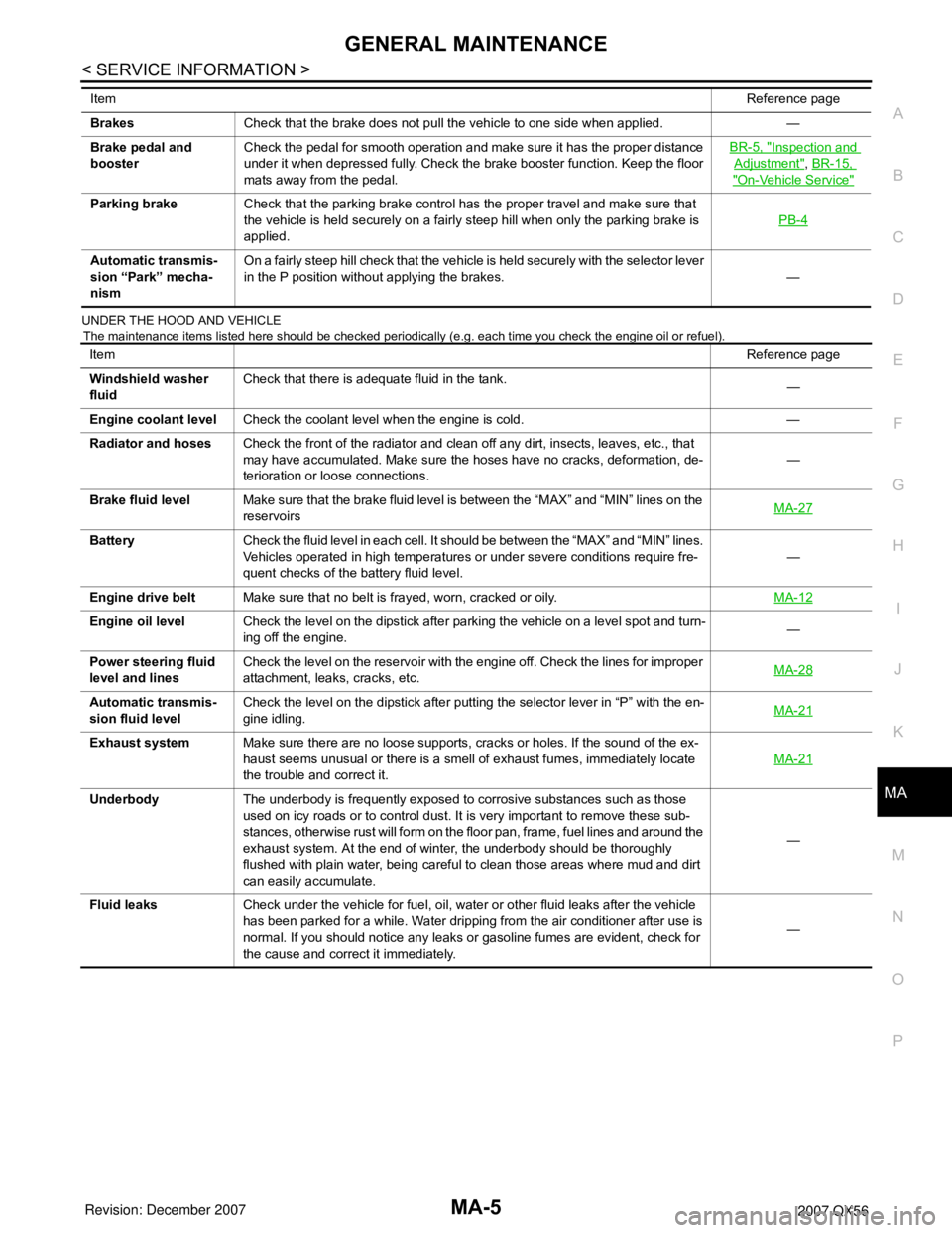
UNDER THE HOOD AND VEHICLE
The maintenance items listed here should be checked periodically (e.g. each time you check the engine oil or refuel).
BrakesCheck that the brake does not pull the vehicle to one side when applied. —
Brake pedal and
boosterCheck the pedal for smooth operation and make sure it has the proper distance
under it when depressed fully. Check the brake booster function. Keep the floor
mats away from the pedal.BR-5, "
Inspection and
Adjustment", BR-15,
"On-Vehicle Service"
Parking brakeCheck that the parking brake control has the proper travel and make sure that
the vehicle is held securely on a fairly steep hill when only the parking brake is
applied.PB-4
Automatic transmis-
sion “Park” mecha-
nismOn a fairly steep hill check that the vehicle is held securely with the selector lever
in the P position without applying the brakes. — ItemReference page
ItemReference page
Windshield washer
fluidCheck that there is adequate fluid in the tank.
—
Engine coolant levelCheck the coolant level when the engine is cold. —
Radiator and hosesCheck the front of the radiator and clean off any dirt, insects, leaves, etc., that
may have accumulated. Make sure the hoses have no cracks, deformation, de-
terioration or loose connections.—
Brake fluid levelMake sure that the brake fluid level is between the “MAX” and “MIN” lines on the
reservoirsMA-27
BatteryCheck the fluid level in each cell. It should be between the “MAX” and “MIN” lines.
Vehicles operated in high temperatures or under severe conditions require fre-
quent checks of the battery fluid level.—
Engine drive beltMake sure that no belt is frayed, worn, cracked or oily.MA-12
Engine oil levelCheck the level on the dipstick after parking the vehicle on a level spot and turn-
ing off the engine.—
Power steering fluid
level and linesCheck the level on the reservoir with the engine off. Check the lines for improper
attachment, leaks, cracks, etc.MA-28
Automatic transmis-
sion fluid levelCheck the level on the dipstick after putting the selector lever in “P” with the en-
gine idling.MA-21
Exhaust systemMake sure there are no loose supports, cracks or holes. If the sound of the ex-
haust seems unusual or there is a smell of exhaust fumes, immediately locate
the trouble and correct it.MA-21
UnderbodyThe underbody is frequently exposed to corrosive substances such as those
used on icy roads or to control dust. It is very important to remove these sub-
stances, otherwise rust will form on the floor pan, frame, fuel lines and around the
exhaust system. At the end of winter, the underbody should be thoroughly
flushed with plain water, being careful to clean those areas where mud and dirt
can easily accumulate.—
Fluid leaksCheck under the vehicle for fuel, oil, water or other fluid leaks after the vehicle
has been parked for a while. Water dripping from the air conditioner after use is
normal. If you should notice any leaks or gasoline fumes are evident, check for
the cause and correct it immediately.—
Page 2372 of 3061
MA-10
< SERVICE INFORMATION >
RECOMMENDED FLUIDS AND LUBRICANTS
RECOMMENDED FLUIDS AND LUBRICANTS
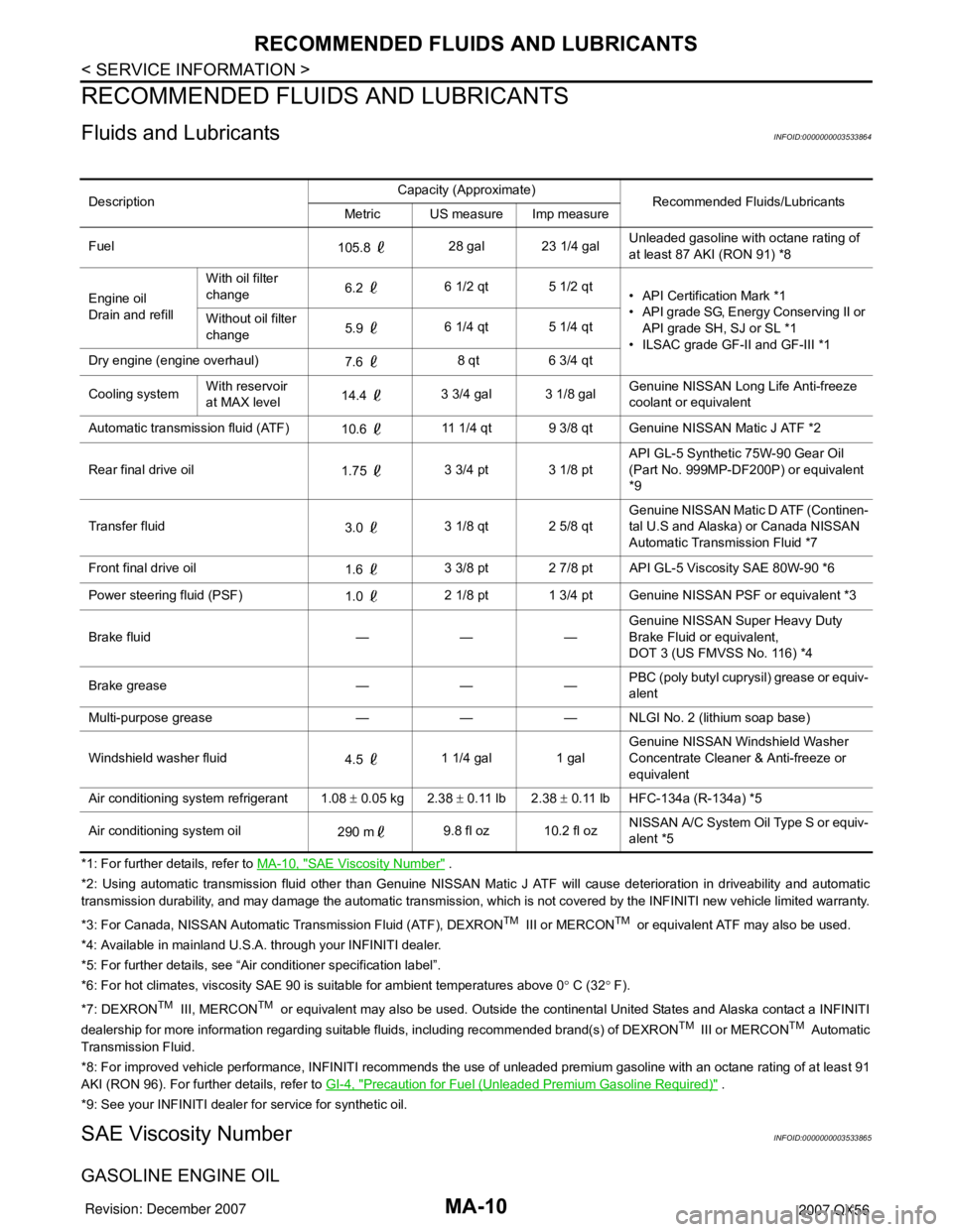
Fluids and LubricantsINFOID:0000000003533864
*1: For further details, refer to MA-10, "SAE Viscosity Number" .
*2: Using automatic transmission fluid other than Genuine NISSAN Matic J ATF will cause deterioration in driveability and automatic
transmission durability, and may damage the automatic transmission, which is not covered by the INFINITI new vehicle limited warranty.
*3: For Canada, NISSAN Automatic Transmission Fluid (ATF), DEXRON
TM III or MERCONTM or equivalent ATF may also be used.
*4: Available in mainland U.S.A. through your INFINITI dealer.
*5: For further details, see “Air conditioner specification label”.
*6: For hot climates, viscosity SAE 90 is suitable for ambient temperatures above 0° C (32° F).
*7: DEXRON
TM III, MERCONTM or equivalent may also be used. Outside the continental United States and Alaska contact a INFINITI
dealership for more information regarding suitable fluids, including recommended brand(s) of DEXRONTM III or MERCONTM Automatic
Transmission Fluid.
*8: For improved vehicle performance, INFINITI recommends the use of unleaded premium gasoline with an octane rating of at least 91
AKI (RON 96). For further details, refer to GI-4, "
Precaution for Fuel (Unleaded Premium Gasoline Required)" .
*9: See your INFINITI dealer for service for synthetic oil.
SAE Viscosity NumberINFOID:0000000003533865
GASOLINE ENGINE OIL
DescriptionCapacity (Approximate)
Recommended Fluids/Lubricants
Metric US measure Imp measure
Fuel
105.8 28 gal 23 1/4 galUnleaded gasoline with octane rating of
at least 87 AKI (RON 91) *8
Engine oil
Drain and refillWith oil filter
change6.2 6 1/2 qt 5 1/2 qt
• API Certification Mark *1
• API grade SG, Energy Conserving II or
API grade SH, SJ or SL *1
• ILSAC grade GF-II and GF-III *1 Without oil filter
change5.9 6 1/4 qt 5 1/4 qt
Dry engine (engine overhaul)
7.6 8 qt 6 3/4 qt
Cooling systemWith reservoir
at MAX level14.4 3 3/4 gal 3 1/8 galGenuine NISSAN Long Life Anti-freeze
coolant or equivalent
Automatic transmission fluid (ATF)
10.6 11 1/4 qt 9 3/8 qt Genuine NISSAN Matic J ATF *2
Rear final drive oil
1.75 3 3/4 pt 3 1/8 ptAPI GL-5 Synthetic 75W-90 Gear Oil
(Part No. 999MP-DF200P) or equivalent
*9
Transfer fluid
3.0 3 1/8 qt 2 5/8 qtGenuine NISSAN Matic D ATF (Continen-
tal U.S and Alaska) or Canada NISSAN
Automatic Transmission Fluid *7
Front final drive oil
1.6 3 3/8 pt 2 7/8 pt API GL-5 Viscosity SAE 80W-90 *6
Power steering fluid (PSF)
1.0 2 1/8 pt 1 3/4 pt Genuine NISSAN PSF or equivalent *3
Brake fluid — — —Genuine NISSAN Super Heavy Duty
Brake Fluid or equivalent,
DOT 3 (US FMVSS No. 116) *4
Brake grease — — —PBC (poly butyl cuprysil) grease or equiv-
alent
Multi-purpose grease — — — NLGI No. 2 (lithium soap base)
Windshield washer fluid
4.5 1 1/4 gal 1 galGenuine NISSAN Windshield Washer
Concentrate Cleaner & Anti-freeze or
equivalent
Air conditioning system refrigerant 1.08 ± 0.05 kg 2.38 ± 0.11 lb 2.38 ± 0.11 lb HFC-134a (R-134a) *5
Air conditioning system oil
290 m9.8 fl oz 10.2 fl ozNISSAN A/C System Oil Type S or equiv-
alent *5
Page 2374 of 3061

MA-12
< SERVICE INFORMATION >
ENGINE MAINTENANCE
ENGINE MAINTENANCE
Checking Drive BeltsINFOID:0000000003533866
WARNING:
Be sure to perform when the engine is stopped.
1. Remove air duct and resonator assembly (inlet) when inspecting drive belt.
2. Make sure that indicator (single line notch) of each auto tensioner is within the allowable working range
“A” (between three line notches) as shown.
NOTE:
• Check the auto tensioner indication when the engine is cold.
• When the new drive belt is installed, the range should be “A” as shown.
• The indicator notch is located on the moving side of the auto tensioner.
3. Visually check entire belt for wear, damage or cracks.
4. If the indicator is out of allowable working range or belt is damaged, replace the belt. Refer to EM-13,
"Removal and Installation".
DRIVE BELT TENSION
There is no manual drive belt tension adjustment. The drive belt tension is automatically adjusted by the auto
tensioner.
Changing Engine CoolantINFOID:0000000003533867
WARNING:
• To avoid being scalded, never change the coolant when the engine is hot.
• Wrap a thick cloth around the cap to carefully remove the cap. First, turn the cap a quarter of a turn
to release any built-up pressure, then push down and turn the cap all the way to remove it.
DRAINING ENGINE COOLANT
1. Turn ignition switch ON and set temperature control lever all the way to HOT position or the highest tem-
perature position. Wait 10 seconds and turn ignition switch OFF.
2. Remove the engine front undercover using power tool.
1. Drive belt 2. Power steering oil pump pulley 3. Generator pulley
4. Crankshaft pulley 5. A/C compressor 6. Idler pulley
7. Cooling fan pulley 8. Water pump pulley 9. Drive belt tensioner
LBIA0391E
Page 2390 of 3061

MA-28
< SERVICE INFORMATION >
CHASSIS AND BODY MAINTENANCE
Check the rotor condition for wear or damage. Refer to BR-18 , BR-
24 .
CALIPER
Check the caliper for any leaks, repair as necessary.
PA D
Check the pads for wear or damage. Refer to BR-18 , BR-24 .
Checking Steering Gear and LinkageINFOID:0000000003533889
STEERING GEAR
• Check the steering gear housing for looseness, damage and oil
leakage as shown.
• Check the steering column connections for looseness.
STEERING LINKAGE
• Check the ball joint, dust cover and other component parts for looseness, wear, damage, and grease leak-
age.
Checking Power Steering Fluid and LineINFOID:0000000003533890
CHECKING FLUID LEVEL
SMA260A
SMA922A
LMA051
SGIA0506E
Page 2391 of 3061
CHASSIS AND BODY MAINTENANCE
MA-29
< SERVICE INFORMATION >
C
D
E
F
G
H
I
J
K
MA
B
MA
N
O
P
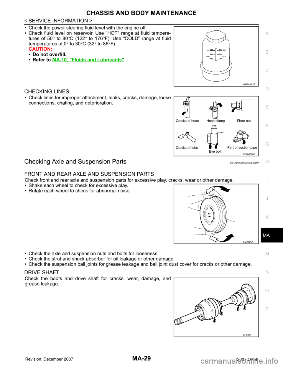
• Check the power steering fluid level with the engine off.
• Check fluid level on reservoir. Use “HOT” range at fluid tempera-
tures of 50° to 80°C (122° to 176°F). Use “COLD” range at fluid
temperatures of 0° to 30°C (32° to 86°F).
CAUTION:
• Do not overfill.
• Refer to MA-10, "
Fluids and Lubricants" .
CHECKING LINES
• Check lines for improper attachment, leaks, cracks, damage, loose
connections, chafing, and deterioration.
Checking Axle and Suspension PartsINFOID:0000000003533891
FRONT AND REAR AXLE AND SUSPENSION PARTS
Check front and rear axle and suspension parts for excessive play, cracks, wear or other damage.
• Shake each wheel to check for excessive play.
• Rotate each wheel to check for abnormal noise.
• Check the axle and suspension nuts and bolts for looseness.
• Check the strut and shock absorber for oil leakage or other damage.
• Check the suspension ball joints for grease leakage and ball joint dust cover for cracks or other damage.
DRIVE SHAFT
Check the boots and drive shaft for cracks, wear, damage, and
grease leakage.
LGIA0021E
SGIA0506E
SMA525A
SFA901