power steering INFINITI QX56 2007 Factory Manual PDF
[x] Cancel search | Manufacturer: INFINITI, Model Year: 2007, Model line: QX56, Model: INFINITI QX56 2007Pages: 3061, PDF Size: 64.56 MB
Page 2462 of 3061

PG-60
< SERVICE INFORMATION >
HARNESS
Code Section Wiring Diagram Name
A/C,A ATC Auto Air Conditioner
A/SUSP RSU Rear Air Suspension
AF1B1 EC Air Fuel Ratio (A/F) Sensor 1 (Bank 1)
AF1B2 EC Air Fuel Ratio (A/F) Sensor 1 (Bank 2)
AF1HB1 EC Air Fuel Ratio (A/F) Sensor 1 (Bank 1)
AF1HB2 EC Air Fuel Ratio (A/F) Sensor 1 (Bank 2)
APPS1 EC Accelerator Pedal Position Sensor
APPS2 EC Accelerator Pedal Position Sensor
APPS3 EC Accelerator Pedal Position Sensor
ASC/BS EC ASCD Brake Switch
ASC/SW EC ASCD Steering Switch
ASCBOF EC ASCD Brake Switch
ASCIND EC ASCD Indicator
A/T AT A/T Assembly
AT/IND DI A/T Indicator Lamp
AUDIO AV Audio
AUT/DP SE Automatic Drive Positioner
AUTO/L LT Auto Light Control
B/CLOS BL Back Door Auto Closure System
BACK/L LT Back-up Lamp
BRK/SW EC Brake Switch
CAN EC CAN Communication Line
CAN LAN CAN System
CHARGE SC Charging System
CHIME DI Warning Chime
CLOCK DI Clock
COOL/F EC Cooling Fan Control
COMBSW LT Combination Switch
COMM AV Audio Visual Communication System
COMPAS DI Compass and Thermometer
D/LOCK BL Power Door Lock
DEF GW Rear Window Defogger
DTRL LT Headlamp - With Daytime Light System
DVD AV DVD Entertainment System
ECM/PW EC ECM Power Supply for Back-Up
ECTS EC Engine Coolant Temperature Sensor
ETC1 EC Electric Throttle Control Function
ETC2 EC Throttle Control Motor Relay
ETC3 EC Throttle Control Motor
F/FOG LT Front Fog Lamp
F/PUMP EC Fuel Pump
FTTS EC Fuel Tank Temperature Sensor
FUELB1 EC Fuel Injection System Bank 1
FUELB2 EC Fuel Injection System Bank 2
H/AIM LT Headlamp Aiming Control
H/PHON AV Hands Free Telephone
H/LAMP LT Headlamp
HORN WW Horn
HSEAT SE Heated Seat
ICC ACS Intelligent Cruise Control
ICCBOF EC ICC Brake Switch
Page 2463 of 3061

HARNESS
PG-61
< SERVICE INFORMATION >
C
D
E
F
G
H
I
J
L
MA
B
PG
N
O
P
ICC/BS EC ICC Steering Switch
ICC/SW EC ICC Brake Switch
I/MIRR GW Inside Mirror (Auto Anti-Dazzling Mirror)
IATS EC Intake Air Temperature Sensor
IGNSYS EC Ignition System
ILL LT Illumination
INJECT EC Injector
INT/L LT Room/Map, Vanity, Cargo, Personal, Foot, Step, and Puddle Lamps
KEYLES BL Remote Keyless Entry System
KS EC Knock Sensor
MAFS EC Mass Air Flow Sensor
MAIN EC Main Power Supply and Ground Circuit
METER DI Speedometer, Tachometer, Temp. and Fuel Gauges
MIL/DL EC Malfunction Indicator Lamp
MIRROR GW Door Mirror
NATS BL Nissan Anti-Theft System
NAVI AV Navigation System
O2H2B1 EC Rear Heated Oxygen Sensor 2 Heater Bank 1
O2H2B2 EC Rear Heated Oxygen Sensor 2 Heater Bank 2
O2S2B1 EC Heated Oxygen Sensor 2 Bank 1
O2S2B2 EC Heated Oxygen Sensor 2 Bank 2
P/SCKT WW Power Socket
PGC/V EC EVAP Canister Purge Volume Control Solenoid Valve
PHASE EC Camshaft Position Sensor (PHASE) (Bank 1)
PNP/SW EC Park/Neutral Position Switch
POS EC Crankshaft Position Sensor (POS)
POWER PG Power Supply Routing
PRE/SE EC EVAP Control System Pressure Sensor
PS/SEN EC Power Steering Pressure Sensor
R/VIEW DI Rear View Monitor
RP/SEN EC Refrigerant Pressure Sensor
SEN/PW EC Sensor Power Supply
SHIFT AT A/T Shift Lock System
SONAR DI Rear Sonar System
SROOF RF Sunroof
SRS SRS Supplemental Restraint System
START SC Starting System
STOP/L LT Stop Lamp
T/TOW LT Trailer Tow
T/WARN WT Low Tire Pressure Warning System
TAIL/L LT Parking, License and Tail Lamps
T/F TF Transfer Case
TPS1 EC Throttle Position Sensor
TPS2 EC Throttle Position Sensor
TPS3 EC Throttle Position Sensor
TRNSCV BL HOMELINK® Universal Transceiver
TURN LT Turn Signal and Hazard Warning Lamps
VDC BRC Vehicle Dynamic Control System
VEHSEC BL Vehicle security (theft warning) system
VENT/V EC EVAP Canister Vent Control Valve
W/ANT AV Audio Antenna
WARN DI Warning Lamps
Page 2492 of 3061

PS-1
STEERING
C
D
E
F
H
I
J
K
L
M
SECTION PS
A
B
PS
N
O
P
CONTENTS
POWER STEERING SYSTEM
SERVICE INFORMATION ............................2
PRECAUTIONS ...................................................2
Precaution for Supplemental Restraint System
(SRS) "AIR BAG" and "SEAT BELT PRE-TEN-
SIONER" ...................................................................
2
Precaution for Steering System ................................2
PREPARATION ...................................................3
Special Service Tool .................................................3
Commercial Service Tool ..........................................4
NOISE, VIBRATION AND HARSHNESS
(NVH) TROUBLESHOOTING .............................
5
NVH Troubleshooting Chart ......................................5
POWER STEERING FLUID ................................6
Checking Fluid Level .................................................6
Checking Fluid Leakage ............................................6
Air Bleeding Hydraulic System ..................................6
STEERING WHEEL .............................................7
On-Vehicle Inspection and Service ...........................7
Removal and Installation ...........................................8
TILT SYSTEM ......................................................9
Removal and Installation ..........................................9
STEERING COLUMN ........................................10
Removal and Installation .........................................10
Disassembly and Assembly .....................................13
POWER STEERING GEAR AND LINKAGE ....15
Removal and Installation .........................................15
Disassembly and Assembly .....................................17
POWER STEERING OIL PUMP .......................21
On-Vehicle Inspection and Service .........................21
Removal and Installation .........................................21
Disassembly and Assembly .....................................22
HYDRAULIC LINE ............................................23
Removal and Installation .........................................23
SERVICE DATA AND SPECIFICATIONS
(SDS) .................................................................
25
Steering Wheel ........................................................25
Steering Column ......................................................25
Steering Outer Socket and Inner Socket .................26
Steering Gear ..........................................................26
Oil Pump ..................................................................27
Steering Fluid ..........................................................27
Page 2495 of 3061
PS-4
< SERVICE INFORMATION >
PREPARATION
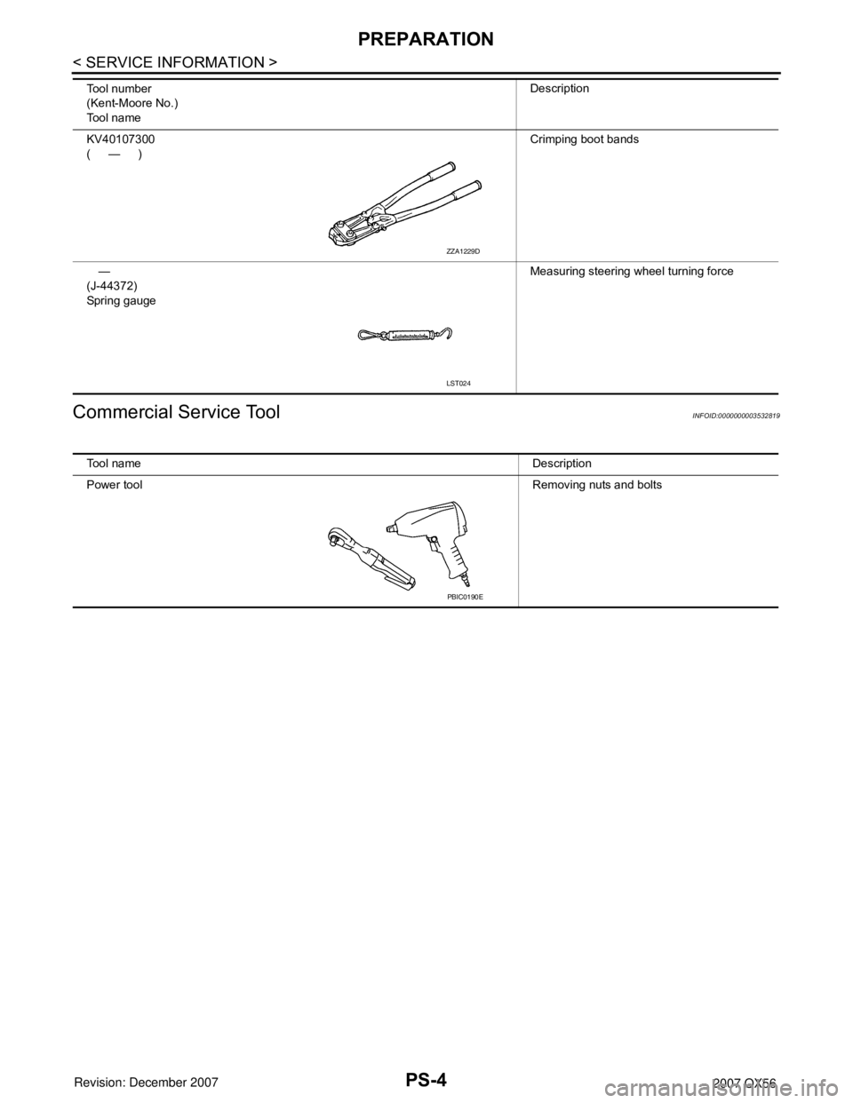
Commercial Service Tool
INFOID:0000000003532819
KV40107300
(—)Crimping boot bands
—
(J-44372)
Spring gaugeMeasuring steering wheel turning force Tool number
(Kent-Moore No.)
Tool nameDescription
ZZA1229D
LST024
Tool nameDescription
Power toolRemoving nuts and bolts
PBIC0190E
Page 2497 of 3061

PS-6
< SERVICE INFORMATION >
POWER STEERING FLUID
POWER STEERING FLUID
Checking Fluid LevelINFOID:0000000003532821
Check power steering fluid level with engine off, referring to the scale
on reservoir tank.
Use HOT range for fluid temperatures of 50° – 80°C (122° – 176°F).
Use COLD range for fluid temperatures of 0° – 30°C (32° – 86°F).
CAUTION:
• Do not overfill.
• Do not reuse any used power steering fluid.
• Recommended fluid is Genuine NISSAN PSF or equivalent.
Refer to MA-10
.
Checking Fluid LeakageINFOID:0000000003532822
Check the hydraulic piping lines for improper attachment and for
leaks, cracks, damage, loose connections, chafing or deterioration.
1. Run engine until fluid temperature reaches 50° – 80°C (122° –
176°F) in reservoir tank. Keep engine speed idle.
2. Turn steering wheel right-to-left several times.
3. Hold steering wheel at each “lock” position for five seconds to
check fluid leakage.
CAUTION:
Do not hold steering wheel in a locked position for more
than 10 seconds. (There is the possibility that oil pump may
be damaged.)
4. If fluid leakage at connections is noticed, then loosen flare nut and then retighten. Do not over tighten con-
nector as this can damage O-ring, washer and connector.
5. If fluid leakage from oil pump is noticed, check oil pump. Refer to PS-21
.
6. Check steering gear boots for accumulation of fluid indicating a leak from the steering gear.
Air Bleeding Hydraulic SystemINFOID:0000000003532823
Incomplete air bleeding causes the following. When this happens, bleed air again.
• Air bubbles in reservoir tank.
• Clicking noise in oil pump.
• Excessive buzzing in oil pump.
NOTE:
When vehicle is stationary or while steering wheel is being turned slowly, some noise may be heard from oil
pump or gear. This noise is normal and does not affect any system.
1. Stop engine, and then turn steering wheel fully to right and left several times.
CAUTION:
Do not allow steering fluid reservoir tank to go below the MIN level line. Check tank frequently and
add fluid as needed.
2. Run engine at idle speed. Turn steering wheel fully right and then fully left, hold for about three seconds.
Then check for fluid leakage.
3. Repeat step 2 several times at about three second intervals.
CAUTION:
Do not hold steering wheel in the locked position for more than 10 seconds. (There is the possibil-
ity that oil pump may be damaged.)
4. Check for air bubbles or cloudy fluid.
5. If air bubbles or cloudiness still exists, stop engine, perform steps 2 and 3 again until air bubbles or cloud-
iness does not exist.
6. Stop engine, check fluid level.
LGIA0021E
SGIA0506E
Page 2498 of 3061
STEERING WHEEL
PS-7
< SERVICE INFORMATION >
C
D
E
F
H
I
J
K
L
MA
B
PS
N
O
P
STEERING WHEEL
On-Vehicle Inspection and ServiceINFOID:0000000003532824
CHECKING CONDITION OF INSTALLATION
• Check installation condition of steering gear assembly, front suspension, axle and steering column.
• Check if movement exists when steering wheel is moved up and down, to the left and right and to the axial
direction.
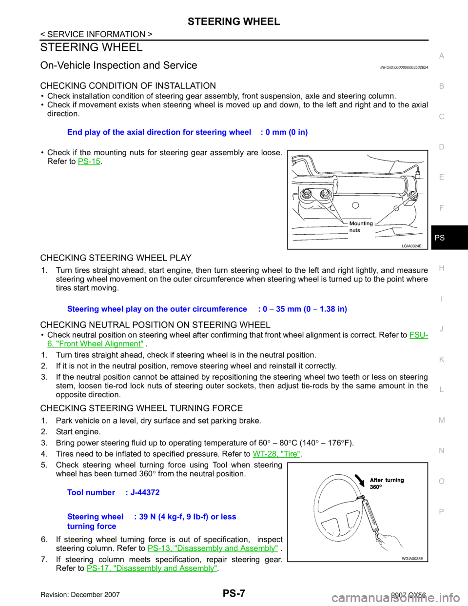
• Check if the mounting nuts for steering gear assembly are loose.
Refer to PS-15
.
CHECKING STEERING WHEEL PLAY
1. Turn tires straight ahead, start engine, then turn steering wheel to the left and right lightly, and measure
steering wheel movement on the outer circumference when steering wheel is turned up to the point where
tires start moving.
CHECKING NEUTRAL POSITION ON STEERING WHEEL
• Check neutral position on steering wheel after confirming that front wheel alignment is correct. Refer to FSU-
6, "Front Wheel Alignment" .
1. Turn tires straight ahead, check if steering wheel is in the neutral position.
2. If it is not in the neutral position, remove steering wheel and reinstall it correctly.
3. If the neutral position cannot be attained by repositioning the steering wheel two teeth or less on steering
stem, loosen tie-rod lock nuts of steering outer sockets, then adjust tie-rods by the same amount in the
opposite direction.
CHECKING STEERING WHEEL TURNING FORCE
1. Park vehicle on a level, dry surface and set parking brake.
2. Start engine.
3. Bring power steering fluid up to operating temperature of 60° – 80°C (140° – 176°F).
4. Tires need to be inflated to specified pressure. Refer to WT-28, "
Tire".
5. Check steering wheel turning force using Tool when steering
wheel has been turned 360° from the neutral position.
6. If steering wheel turning force is out of specification, inspect
steering column. Refer to PS-13, "
Disassembly and Assembly" .
7. If steering column meets specification, repair steering gear.
Refer to PS-17, "
Disassembly and Assembly". End play of the axial direction for steering wheel : 0 mm (0 in)
LGIA0024E
Steering wheel play on the outer circumference : 0 − 35 mm (0 − 1.38 in)
Tool number : J-44372
Steering wheel
turning force: 39 N (4 kg-f, 9 lb-f) or less
WGIA0035E
Page 2506 of 3061
POWER STEERING GEAR AND LINKAGE
PS-15
< SERVICE INFORMATION >
C
D
E
F
H
I
J
K
L
MA
B
PS
N
O
P
POWER STEERING GEAR AND LINKAGE
Removal and InstallationINFOID:0000000003532829
CAUTION:
Spiral cable may snap due to steering operation if steering column is separated from steering gear
assembly. Therefore secure steering wheel to avoid turning.
REMOVAL
1. Turn wheels to the straight-ahead position.
2. Remove tires from vehicle using power tool.
3. Remove undercover using power tool.
4. On 4WD model, remove front final drive, then support drive shafts with wire. Refer to FFD-12, "
Removal
and Installation" .
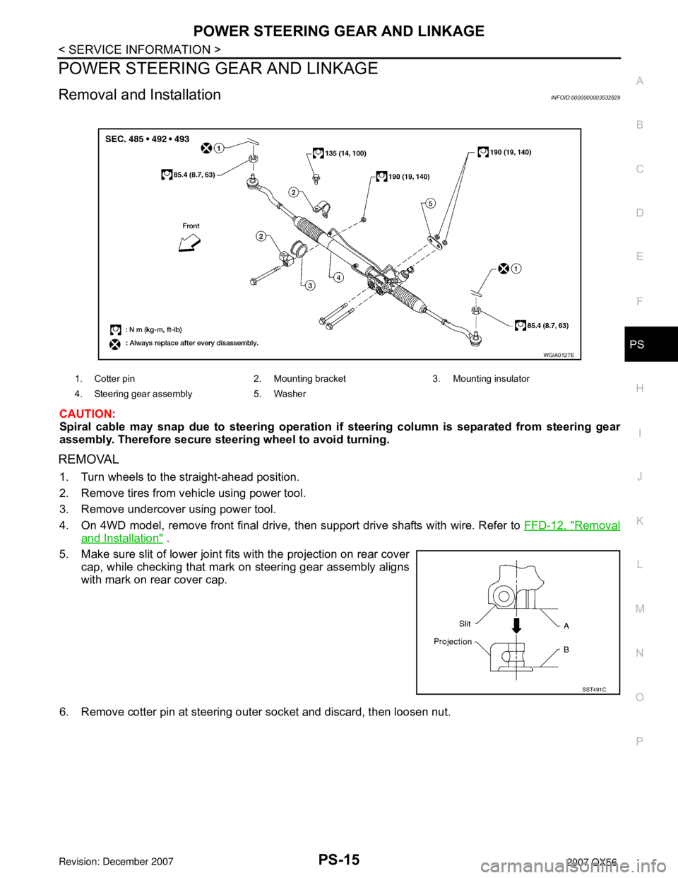
5. Make sure slit of lower joint fits with the projection on rear cover
cap, while checking that mark on steering gear assembly aligns
with mark on rear cover cap.
6. Remove cotter pin at steering outer socket and discard, then loosen nut.
1. Cotter pin 2. Mounting bracket 3. Mounting insulator
4. Steering gear assembly 5. Washer
WGIA0127E
SST491C
Page 2507 of 3061
PS-16
< SERVICE INFORMATION >
POWER STEERING GEAR AND LINKAGE
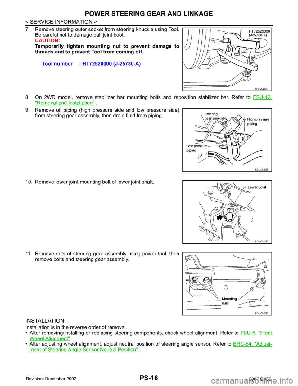
7. Remove steering outer socket from steering knuckle using Tool.
Be careful not to damage ball joint boot.
CAUTION:
Temporarily tighten mounting nut to prevent damage to
threads and to prevent Tool from coming off.
8. On 2WD model, remove stabilizer bar mounting bolts and reposition stabilizer bar. Refer to FSU-12,
"Removal and Installation" .
9. Remove oil piping (high pressure side and low pressure side)
from steering gear assembly, then drain fluid from piping.
10. Remove lower joint mounting bolt of lower joint shaft.
11. Remove nuts of steering gear assembly using power tool, then
remove bolts and steering gear assembly.
INSTALLATION
Installation is in the reverse order of removal.
• After removing/installing or replacing steering components, check wheel alignment. Refer to FSU-6, "
Front
Wheel Alignment" .
• After adjusting wheel alignment, adjust neutral position of steering angle sensor. Refer to BRC-54, "
Adjust-
ment of Steering Angle Sensor Neutral Position" . Tool number : HT72520000 (J-25730-A)
SDIA1434E
LGIA0032E
LGIA0029E
LGIA0024E
Page 2508 of 3061

POWER STEERING GEAR AND LINKAGE
PS-17
< SERVICE INFORMATION >
C
D
E
F
H
I
J
K
L
MA
B
PS
N
O
P
• With steering wheel in straight ahead position, make sure slit of
lower joint fits with the projection on rear cover cap, while checking
that mark on steering gear assembly aligns with mark on rear
cover cap
• After installation, bleed the air from the steering hydraulic system. Refer to PS-6, "
Air Bleeding Hydraulic
System" .
INSPECTION AFTER INSTALLATION
Check if steering wheel turns smoothly when it is turned several times fully to the left and right lock positions.
Disassembly and AssemblyINFOID:0000000003532830
CAUTION:
• Secure steering gear assembly with a vise, using copper plates or something similar to prevent it
from being damaged. Do not grip cylinder with a vise.
SST491C
1. Boot clamp 2. Inner socket 3. Boot
4. Boot clamp 5. Outer socket 6. Cylinder tubes
7. Gear housing assembly 8. Connector
WGIA0128E
Page 2509 of 3061
PS-18
< SERVICE INFORMATION >
POWER STEERING GEAR AND LINKAGE
• Before performing disassembly, clean steering gear assembly with kerosene. Be careful not to bring
any kerosene into contact with the discharge and return port connectors.
DISASSEMBLY
1. Remove cylinder tubes from gear housing assembly.
2. Loosen lock nuts of outer sockets, and remove outer sockets.
3. Remove boot clamps of the small diameter side and the large diameter side, then remove boot.
CAUTION:
When removing boots, be careful not to damage inner socket and gear housing assembly. If they
are damaged, change them to avoid oil leaks.
4. Remove inner sockets.
INSPECTION AFTER DISASSEMBLY
Boot
Check boot for tears, cracks and deformation. Replace if necessary.
Gear Housing Assembly
Check gear housing assembly for dents, cracks or damage. Replace as an assembly if necessary.
Outer Socket and Inner Socket
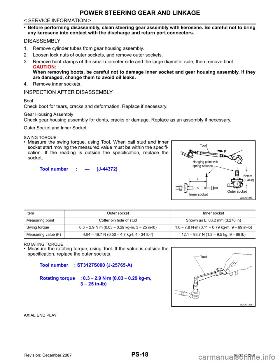
SWING TORQUE
• Measure the swing torque, using Tool. When ball stud and inner
socket start moving the measured value must be within the specifi-
cation. If the reading is outside the specification, replace the
socket.
ROTATING TORQUE• Measure the rotating torque, using Tool. If the value is outside the
specification, replace the outer sockets.
AXIAL END PLAY
Tool number : — (J-44372)
WGIA0131E
Item Outer socket Inner socket
Measuring point Cotter pin hole of stud Shown as L: 83.2 mm (3.276 in)
Swing torque 0.3 − 2.9 N·m (0.03 − 0.29 kg-m, 3 − 25 in-lb) 1.0 − 7.8 N·m (0.11 − 0.79 kg-m, 9 − 69 in-lb)
Measuring value (F) 4.84 − 46.7 N (0.50 − 4.7 kg-f, 4 - 34 lb-f) 12.1 − 93.7 N (1.3 − 9.5 kg, 9 − 69 lb)
Tool number : ST3127S000 (J-25765-A)
Rotating torque : 0.3 − 2.9 N·m (0.03 − 0.29 kg-m,
3 − 25 in-lb)
WGIA0132E