transmission fluid INFINITI QX56 2007 Factory Repair Manual
[x] Cancel search | Manufacturer: INFINITI, Model Year: 2007, Model line: QX56, Model: INFINITI QX56 2007Pages: 3061, PDF Size: 64.56 MB
Page 2112 of 3061

IDX-8
ALPHABETICAL INDEX
Three way catalyst ............................................ EM-21
Three way catalyst function (Bank 1) ............... EC-376
Three way catalyst function (Bank 2) ............... EC-376
Three way catalyst precautions ............................ GI-5
Throttle control motor ....................................... EC-601
Throttle control motor relay .............................. EC-589
Throttle position sensor (TPS) .. EC-224, EC-343, EC-
514, EC-516, EC-621
Throttle valve closed position learning ............... EC-80
Tie-rod ............................................................... PS-15
Timing chain ..................................................... EM-37
Tire rotation ....................................................... MA-28
Tire size .............................................................. GI-51
Torque converter installation AT-239, AT-240, AT-243,
AT-244
Torque convertor clutch solenoid valve ... AT-114, AT-
116
Tow truck towing ................................................. GI-44
Towing point ....................................................... GI-45
TPS1 - Wiring diagram .................................... EC-345
TPS2 - Wiring diagram .................................... EC-226
TPS3 - Wiring diagram .................................... EC-623
Traction control system - Wiring diagram ....... BRC-16
Transfer control device ............. TF-75, TF-79, TF-138
Transfer control unit inspection table ................. TF-35
Transfer dropping resistor .................................. TF-89
Transfer fluid temperature sensor TF-103, TF-154, TF-
167
Transfer motor .................................... TF-101, TF-142
Transfer motor relay ........................................ TF-101
Transfer oil replacement ................................... MA-24
Transfer serial number ........................................ GI-50
Transmission serial number ................................ GI-50
Tread-FR&RR (Dimensions) ............................... GI-51
Trim ..................................................................... EI-35
TRNSCV - Wiring diagram .................. BL-130, BL-146
Trouble diagnoses .............................................. GI-11
Turbine revolution sensor ................................ AT-105
TURN - Wiring diagram ...................................... LT-67
Turn signal lamp ................................................. LT-63
Two trip detection logic ...................................... EC-49
Two-pole lift ........................................................ GI-43
V
Vacuum hose (brake system) ............................ BR-20
Vacuum hose drawing (Engine control) ........... EC-106
Valve clearance ................................................ EM-55
Valve guide ....................................................... EM-69
Vanity mirror lamp ............................................. LT-110
VDC (vehicle dynamics control) ........................ BRC-7
VDC -Wiring diagram ...................................... BRC-16
Vehicle identification number .............................. GI-49
Vehicle recovery (freeing a stuck vehicle) .......... GI-45
Vehicle security (theft warning) system ............. BL-67
Vehicle speed sensor (VSS) ............................ EC-464
VEHSEC - Wiring diagram ................................. BL-71
VENT/V - Wiring diagram .................. EC-412, EC-419
VIN registration .................................................. EC-79
Viscosity number (SAE) .................................... MA-12
VSS A/T - Wiring diagram .................. AT-107, AT-109
W
W/ANT - Wiring diagram .................................... AV-59
Wait detection switch ......................................... TF-68
WARN - Wiring diagram ...................................... DI-29
Warning chime .................................................... DI-38
Warning lamps .................................................... DI-28
Washer, front ..................................................... WW-4
Washer, rear .................................................... WW-29
Water pump ...................................................... CO-19
Water temperature gauge ..................................... DI-5
Wheel alignment (front) ..................................... FSU-6
Wheel alignment (rear) ................................... RSU-25
Wheel bearing (front) ........................................ FAX-5
Wheel bearing (rear) ......................................... RAX-5
Wheel hub (rear) ............................................... RAX-5
Wheel size .......................................................... GI-51
Wheelbase (Dimensions) .................................... GI-51
Width (Dimensions) ............................................. GI-51
WINDOW - Wiring diagram .............................. GW-22
Window, door ...................................... GW-62, GW-65
Windshield ....................................................... GW-11
WIP/R - Wiring diagram ................................... WW-33
WIPER - Wiring diagram .................................... WW-8
Wiper, front ........................................................ WW-4
Wiper, rear ....................................................... WW-29
Wiring Diagram (Cell code) list ......................... PG-62
Wiring diagrams .................................................. GI-15
WT-T/WARN - Wiring diagram .......................... WT-11
Page 2363 of 3061
MA-1
MAINTENANCE
C
D
E
F
G
H
I
J
K
M
SECTION MA
A
B
MA
N
O
P
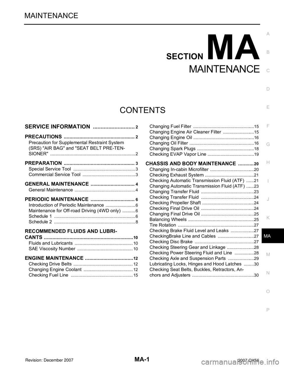
CONTENTS
MAINTENANCE
SERVICE INFORMATION ............................2
PRECAUTIONS ...................................................2
Precaution for Supplemental Restraint System
(SRS) "AIR BAG" and "SEAT BELT PRE-TEN-
SIONER" ...................................................................
2
PREPARATION ...................................................3
Special Service Tool .................................................3
Commercial Service Tool ..........................................3
GENERAL MAINTENANCE ................................4
General Maintenance ................................................4
PERIODIC MAINTENANCE ................................6
Introduction of Periodic Maintenance ........................6
Maintenance for Off-road Driving (4WD only) ...........6
Schedule 1 ................................................................6
Schedule 2 ................................................................8
RECOMMENDED FLUIDS AND LUBRI-
CANTS ................................................................
10
Fluids and Lubricants ..............................................10
SAE Viscosity Number ............................................10
ENGINE MAINTENANCE ...................................12
Checking Drive Belts ...............................................12
Changing Engine Coolant .......................................12
Checking Fuel Line .................................................15
Changing Fuel Filter ................................................15
Changing Engine Air Cleaner Filter .........................15
Changing Engine Oil ................................................16
Changing Oil Filter ...................................................16
Changing Spark Plugs .............................................18
Checking EVAP Vapor Line .....................................19
CHASSIS AND BODY MAINTENANCE ...........20
Changing In-cabin Microfilter ...................................20
Checking Exhaust System .......................................21
Checking Automatic Transmission Fluid (ATF) .......21
Changing Automatic Transmission Fluid (ATF) .......23
Changing Transfer Fluid ..........................................23
Checking Transfer Fluid ..........................................24
Checking Propeller Shaft .........................................24
Checking Final Drive Oil ..........................................24
Changing Final Drive Oil ..........................................25
Balancing Wheels ....................................................25
Tire Rotation ............................................................27
Checking Brake Fluid Level and Leaks ...................27
CheckingBrake Line and Cables .............................27
Checking Disc Brake ...............................................27
Checking Steering Gear and Linkage ......................28
Checking Power Steering Fluid and Line ................28
Checking Axle and Suspension Parts .....................29
Lubricating Locks, Hinges and Hood Latches .........30
Checking Seat Belts, Buckles, Retractors, An-
chors and Adjusters .................................................
30
Page 2368 of 3061

MA-6
< SERVICE INFORMATION >
PERIODIC MAINTENANCE
PERIODIC MAINTENANCE
Introduction of Periodic MaintenanceINFOID:0000000003533860
Two different maintenance schedules are provided, and should be used, depending upon the conditions in
which the vehicle is mainly operated. After 60,000 miles (96,000 km) or 48 months, continue the periodic
maintenance at the same mileage or time intervals, whichever comes first.
Maintenance for Off-road Driving (4WD only)INFOID:0000000003533861
After driving the vehicle off-road through sand, mud, or water; more frequent maintenance may be required for
the following items:
Brake pads and rotors
Brake lines and hoses
Rear final drive oil, transmission fluid, and transfer fluid
Steering linkage
Drive shafts
Engine air cleaner filter
In-cabin microfilters
Schedule 1INFOID:0000000003533862
EMISSION CONTROL SYSTEM MAINTENANCE
Abbreviations: R = Replace. I = Inspect. Correct or replace if necessary. [ ]: At the mileage intervals only
Schedule 1Follow Periodic Maintenance Schedule 1 if your driving habits frequently includes
one or more of the following driving conditions:
• Repeated short trips of less than 5 miles (8 km).
• Repeated short trips of less than 10 miles (16 km) with outside temperatures re-
maining below freezing.
• Operating in hot weather in stop-and-go “rush hour” traffic.
• Extensive idling and/or low speed driving for long distances, such as police, taxi
or door-to-door delivery use.
• Driving in dusty conditions.
• Driving on rough, muddy, or salt spread roads.
• Towing a trailer or using a car-top carrier.Emission Control Sys-
tem MaintenanceMA-6
Chassis and Body
MaintenanceMA-6
Schedule 2Follow Periodic Maintenance Schedule 2 if none of the driving conditions shown
in Schedule 1 apply to the driving habits.Emission Control Sys-
tem MaintenanceMA-8Chassis and Body
MaintenanceMA-8
MAINTENANCE OPERATIONMAINTENANCE INTERVAL
Reference
Section -
Page or -
Content Title Perform at number of miles, kilo-
meters or months, whichever
comes first.Miles x 1,000
(km x 1,000)
Months3.75
(6)
37.50
(12)
611 . 2 5
(18)
915
(24)
1218.75
(30)
1522.5
(36)
1826.25
(42)
2130
(48)
24
Drive belts NOTE (1)MA-12
Air cleaner filter NOTE (2) [R]MA-15
EVAP vapor linesI*MA-19
Fuel linesI*MA-15
Fuel filter NOTE (3)—
Engine coolant NOTE (4)MA-12
Engine oil R R R R R R R RMA-16
Engine oil filter R R R R R R R RMA-16
Spark plugs (double PLATINUM-
TIPPED type)Replace every 105,000 miles (169,000 km).EM-29
Intake and exhaust valve clear-
ance*NOTE (5)EM-103
Page 2369 of 3061
PERIODIC MAINTENANCE
MA-7
< SERVICE INFORMATION >
C
D
E
F
G
H
I
J
K
MA
B
MA
N
O
P
(1) After 60,000 miles (96,000 km) or 48 months, inspect every 15,000 miles (24,000 km) or 12 months. Replace drive belts if damaged.
(2) If operating mainly in dusty conditions, more frequent maintenance may be required.
(3) Maintenance-free item. For service procedures, go to the FL section.
(4) After 60,000 miles (96,000 km) or 48 months, replace every 30,000 miles (48,000 km) or 24 months.
(5) If valve noise increases, inspect valve clearance.
* Maintenance items and intervals with “*” are recommended by NISSAN for reliable vehicle operation. The owner need not perform
such maintenance in order to maintain the emission warranty or manufacturer recall liability. Other maintenance items and intervals are
required.
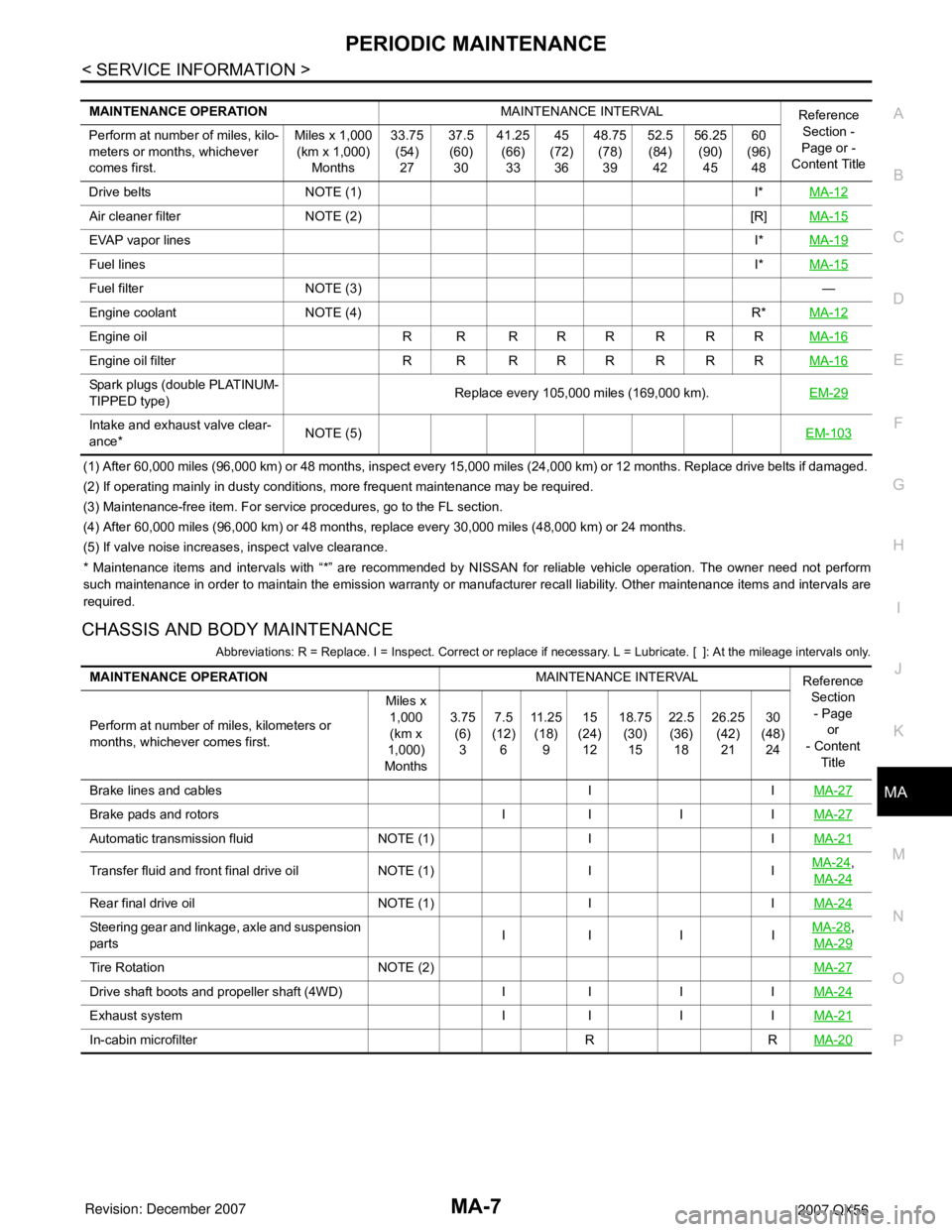
CHASSIS AND BODY MAINTENANCE
Abbreviations: R = Replace. I = Inspect. Correct or replace if necessary. L = Lubricate. [ ]: At the mileage intervals only.
MAINTENANCE OPERATIONMAINTENANCE INTERVAL
Reference
Section -
Page or -
Content Title Perform at number of miles, kilo-
meters or months, whichever
comes first.Miles x 1,000
(km x 1,000)
Months33.75
(54)
2737.5
(60)
3041.25
(66)
3345
(72)
3648.75
(78)
3952.5
(84)
4256.25
(90)
4560
(96)
48
Drive belts NOTE (1) I*MA-12
Air cleaner filter NOTE (2) [R]MA-15
EVAP vapor linesI*MA-19
Fuel linesI*MA-15
Fuel filter NOTE (3)—
Engine coolant NOTE (4) R*MA-12
Engine oil R R R R R R R RMA-16
Engine oil filter R R R R R R R RMA-16
Spark plugs (double PLATINUM-
TIPPED type)Replace every 105,000 miles (169,000 km).EM-29
Intake and exhaust valve clear-
ance*NOTE (5)EM-103
MAINTENANCE OPERATIONMAINTENANCE INTERVAL
Reference
Section
- Page
or
- Content
Title Perform at number of miles, kilometers or
months, whichever comes first.Miles x
1,000
(km x
1,000)
Months3.75
(6)
37.5
(12)
611 . 2 5
(18)
915
(24)
1218.75
(30)
1522.5
(36)
1826.25
(42)
2130
(48)
24
Brake lines and cables I IMA-27
Brake pads and rotors I I I IMA-27
Automatic transmission fluid NOTE (1) I IMA-21
Transfer fluid and front final drive oil NOTE (1) I IMA-24,
MA-24
Rear final drive oil NOTE (1) I IMA-24
Steering gear and linkage, axle and suspension
partsII I IMA-28,
MA-29
Tire Rotation NOTE (2)MA-27
Drive shaft boots and propeller shaft (4WD) I I I IMA-24
Exhaust system I I I IMA-21
In-cabin microfilter R RMA-20
Page 2370 of 3061

MA-8
< SERVICE INFORMATION >
PERIODIC MAINTENANCE
(1) If towing a trailer, or using a car-top carrier, or driving on rough or muddy roads, change (not just inspect) oil at every 30,000 miles
(48,000 km) or 24 months.
(2) Refer to “Tire rotation” under the “General maintenance” heading earlier in this section.
Schedule 2INFOID:0000000003533863
EMISSION CONTROL SYSTEM MAINTENANCE
Abbreviations: R = Replace. I = Inspect. Correct or replace if necessary. [ ]: At the mileage intervals only
(1) After 60,000 miles (96,000 km) or 48 months, inspect every 15,000 miles (24,000 km) or 12 months. Replace drive belts if damaged.
(2) Maintenance-free item. For service procedures, go to FL section.
(3) After 60,000 miles (96,000 km) or 48 months, replace every 30,000 miles (48,000 km) or 24 months.
(4) If valve noise increases, inspect valve clearance.
* Maintenance items and intervals with “*” are recommended by NISSAN for reliable vehicle operation. The owner need not perform
such maintenance in order to maintain the emission warranty or manufacturer recall liability. Other maintenance items and intervals are
required.
CHASSIS AND BODY MAINTENANCE
MAINTENANCE OPERATIONMAINTENANCE INTERVAL
Reference
Section
- Page
or
- Content
Title Perform at number of miles, kilometers or
months, whichever comes first.Miles x
1,000
(km x
1,000)
Months33.75
(54)
2737.5
(60)
3041.25
(66)
3345
(72)
3648.75
(78)
3952.5
(84)
4256.25
(90)
4560
(96)
48
Brake lines and cables I IMA-27
Brake pads and rotors I I I IMA-27
Automatic transmission fluid NOTE (1) I IMA-21
Transfer fluid and front final drive oil NOTE (1) I IMA-24,
MA-24
Rear final drive oil NOTE (1) I IMA-24
Steering gear and linkage, axle and suspen-
sion partsIIIIMA-28,
MA-29
Tire Rotation NOTE (2)MA-27
Drive shaft boots and propeller shaft (4WD) I I I IMA-24
Exhaust system I I I IMA-21
In-cabin microfilter R RMA-20
MAINTENANCE OPERATIONMAINTENANCE INTERVAL
Reference
Section - Page
or - Content Ti-
tle Perform at number of miles, kilometers
or months, whichever comes first.Miles x 1,000
(km x 1,000)
Months7.5
(12)
615
(24)
1222.5
(36)
1830
(48)
2437.5
(60)
3045
(72)
3652.5
(84)
4260
(96)
48
Drive belts NOTE (1) I*MA-12
Air cleaner filter [R] [R]MA-15
EVAP vapor lines I* I*MA-19
Fuel lines I* I*MA-15
Fuel filter NOTE (2) —
Engine coolant NOTE (3) R*MA-12
Engine oil R R R R R R R RMA-16
Engine oil filter R R R R R R R RMA-16
Spark plugs (PLATINUM-TIPPED
type)Replace every 105,000 miles (169,000 km).EM-29
Intake and exhaust valve clearance* NOTE (4)EM-103
Page 2371 of 3061
![INFINITI QX56 2007 Factory Repair Manual PERIODIC MAINTENANCE
MA-9
< SERVICE INFORMATION >
C
D
E
F
G
H
I
J
K
MA
B
MA
N
O
P
Abbreviations: R = Replace. I = Inspect. Correct or replace if necessary. L = Lubricate. [ ]: At the mileage interval INFINITI QX56 2007 Factory Repair Manual PERIODIC MAINTENANCE
MA-9
< SERVICE INFORMATION >
C
D
E
F
G
H
I
J
K
MA
B
MA
N
O
P
Abbreviations: R = Replace. I = Inspect. Correct or replace if necessary. L = Lubricate. [ ]: At the mileage interval](/img/42/57029/w960_57029-2370.png)
PERIODIC MAINTENANCE
MA-9
< SERVICE INFORMATION >
C
D
E
F
G
H
I
J
K
MA
B
MA
N
O
P
Abbreviations: R = Replace. I = Inspect. Correct or replace if necessary. L = Lubricate. [ ]: At the mileage interval only.
(1) Refer to “Tire rotation” under the “General maintenance” heading earlier in this section. MAINTENANCE OPERATIONMAINTENANCE INTERVAL Reference
Section
- Page
or
- Content
Title Perform at number of miles, kilometers or
months, whichever comes first.Miles x 1,000
(km x 1,000)
Months7.5
(12)
615
(24)
1222.5
(36)
1830
(48)
2437.5
(60)
3045
(72)
3652.
5
(84)
4260
(96)
48
Brake lines and cables I I I IMA-27
Brake pads and rotors I I I IMA-27
Automatic transmission fluid I I I IMA-21
Transfer fluid and front final drive oil I I I IMA-24,
MA-24
Rear final drive oil I I I IMA-24
Steering gear and linkage, axle and suspen-
sion partsIIMA-28,
MA-29
Tire rotation NOTE (1)MA-27
Drive shaft boots and propeller shaft
(4WD)IIIIMA-24
Exhaust system I IMA-21
In-cabin microfilter R R R RMA-20
Page 2372 of 3061
MA-10
< SERVICE INFORMATION >
RECOMMENDED FLUIDS AND LUBRICANTS
RECOMMENDED FLUIDS AND LUBRICANTS
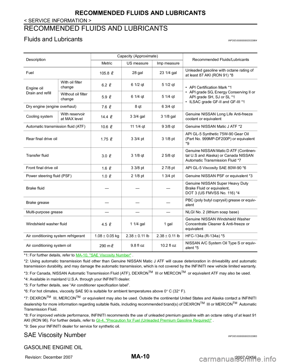
Fluids and LubricantsINFOID:0000000003533864
*1: For further details, refer to MA-10, "SAE Viscosity Number" .
*2: Using automatic transmission fluid other than Genuine NISSAN Matic J ATF will cause deterioration in driveability and automatic
transmission durability, and may damage the automatic transmission, which is not covered by the INFINITI new vehicle limited warranty.
*3: For Canada, NISSAN Automatic Transmission Fluid (ATF), DEXRON
TM III or MERCONTM or equivalent ATF may also be used.
*4: Available in mainland U.S.A. through your INFINITI dealer.
*5: For further details, see “Air conditioner specification label”.
*6: For hot climates, viscosity SAE 90 is suitable for ambient temperatures above 0° C (32° F).
*7: DEXRON
TM III, MERCONTM or equivalent may also be used. Outside the continental United States and Alaska contact a INFINITI
dealership for more information regarding suitable fluids, including recommended brand(s) of DEXRONTM III or MERCONTM Automatic
Transmission Fluid.
*8: For improved vehicle performance, INFINITI recommends the use of unleaded premium gasoline with an octane rating of at least 91
AKI (RON 96). For further details, refer to GI-4, "
Precaution for Fuel (Unleaded Premium Gasoline Required)" .
*9: See your INFINITI dealer for service for synthetic oil.
SAE Viscosity NumberINFOID:0000000003533865
GASOLINE ENGINE OIL
DescriptionCapacity (Approximate)
Recommended Fluids/Lubricants
Metric US measure Imp measure
Fuel
105.8 28 gal 23 1/4 galUnleaded gasoline with octane rating of
at least 87 AKI (RON 91) *8
Engine oil
Drain and refillWith oil filter
change6.2 6 1/2 qt 5 1/2 qt
• API Certification Mark *1
• API grade SG, Energy Conserving II or
API grade SH, SJ or SL *1
• ILSAC grade GF-II and GF-III *1 Without oil filter
change5.9 6 1/4 qt 5 1/4 qt
Dry engine (engine overhaul)
7.6 8 qt 6 3/4 qt
Cooling systemWith reservoir
at MAX level14.4 3 3/4 gal 3 1/8 galGenuine NISSAN Long Life Anti-freeze
coolant or equivalent
Automatic transmission fluid (ATF)
10.6 11 1/4 qt 9 3/8 qt Genuine NISSAN Matic J ATF *2
Rear final drive oil
1.75 3 3/4 pt 3 1/8 ptAPI GL-5 Synthetic 75W-90 Gear Oil
(Part No. 999MP-DF200P) or equivalent
*9
Transfer fluid
3.0 3 1/8 qt 2 5/8 qtGenuine NISSAN Matic D ATF (Continen-
tal U.S and Alaska) or Canada NISSAN
Automatic Transmission Fluid *7
Front final drive oil
1.6 3 3/8 pt 2 7/8 pt API GL-5 Viscosity SAE 80W-90 *6
Power steering fluid (PSF)
1.0 2 1/8 pt 1 3/4 pt Genuine NISSAN PSF or equivalent *3
Brake fluid — — —Genuine NISSAN Super Heavy Duty
Brake Fluid or equivalent,
DOT 3 (US FMVSS No. 116) *4
Brake grease — — —PBC (poly butyl cuprysil) grease or equiv-
alent
Multi-purpose grease — — — NLGI No. 2 (lithium soap base)
Windshield washer fluid
4.5 1 1/4 gal 1 galGenuine NISSAN Windshield Washer
Concentrate Cleaner & Anti-freeze or
equivalent
Air conditioning system refrigerant 1.08 ± 0.05 kg 2.38 ± 0.11 lb 2.38 ± 0.11 lb HFC-134a (R-134a) *5
Air conditioning system oil
290 m9.8 fl oz 10.2 fl ozNISSAN A/C System Oil Type S or equiv-
alent *5
Page 2383 of 3061
CHASSIS AND BODY MAINTENANCE
MA-21
< SERVICE INFORMATION >
C
D
E
F
G
H
I
J
K
MA
B
MA
N
O
P
6. Install the lower glove box in the instrument panel and secure it
with the two hinge pins.
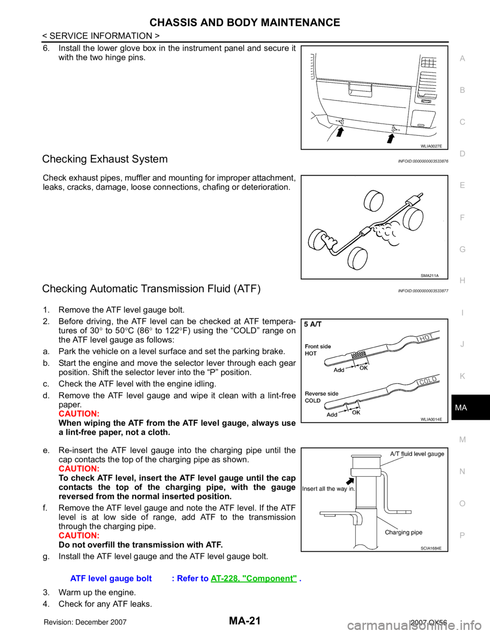
Checking Exhaust SystemINFOID:0000000003533876
Check exhaust pipes, muffler and mounting for improper attachment,
leaks, cracks, damage, loose connections, chafing or deterioration.
Checking Automatic Transmission Fluid (ATF)INFOID:0000000003533877
1. Remove the ATF level gauge bolt.
2. Before driving, the ATF level can be checked at ATF tempera-
tures of 30° to 50°C (86° to 122°F) using the “COLD” range on
the ATF level gauge as follows:
a. Park the vehicle on a level surface and set the parking brake.
b. Start the engine and move the selector lever through each gear
position. Shift the selector lever into the “P” position.
c. Check the ATF level with the engine idling.
d. Remove the ATF level gauge and wipe it clean with a lint-free
paper.
CAUTION:
When wiping the ATF from the ATF level gauge, always use
a lint-free paper, not a cloth.
e. Re-insert the ATF level gauge into the charging pipe until the
cap contacts the top of the charging pipe as shown.
CAUTION:
To check ATF level, insert the ATF level gauge until the cap
contacts the top of the charging pipe, with the gauge
reversed from the normal inserted position.
f. Remove the ATF level gauge and note the ATF level. If the ATF
level is at low side of range, add ATF to the transmission
through the charging pipe.
CAUTION:
Do not overfill the transmission with ATF.
g. Install the ATF level gauge and the ATF level gauge bolt.
3. Warm up the engine.
4. Check for any ATF leaks.
WLIA0027E
SMA211A
WLIA0014E
ATF level gauge bolt : Refer to AT-228, "Component" .
SCIA1684E
Page 2385 of 3061
CHASSIS AND BODY MAINTENANCE
MA-23
< SERVICE INFORMATION >
C
D
E
F
G
H
I
J
K
MA
B
MA
N
O
P
10. Tighten the level gauge bolt to specification.
Changing Automatic Transmission Fluid (ATF)INFOID:0000000003533878
1. Drive the vehicle to warm up the ATF to 80° C (176° F).
2. Stop the engine.
3. Remove the ATF level gauge bolt.
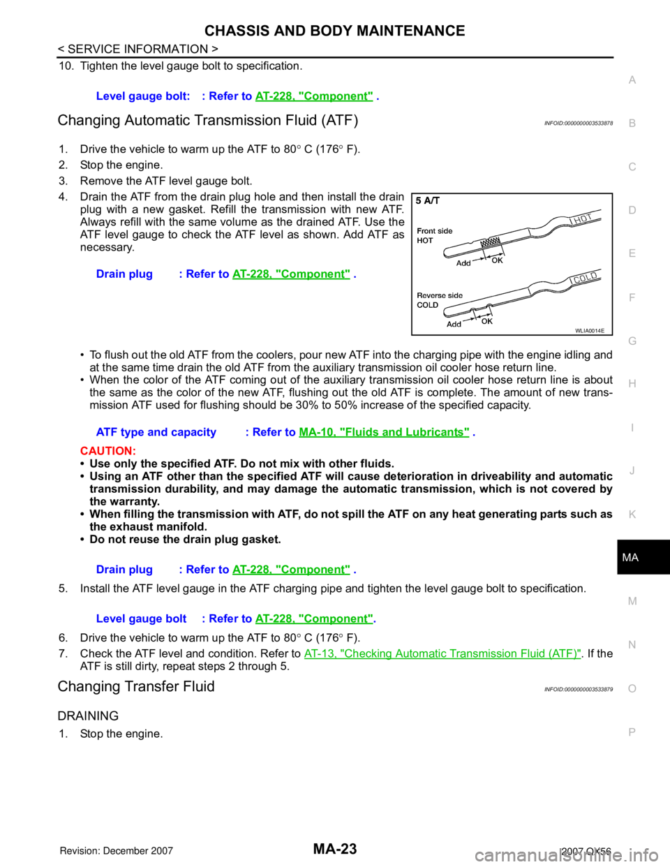
4. Drain the ATF from the drain plug hole and then install the drain
plug with a new gasket. Refill the transmission with new ATF.
Always refill with the same volume as the drained ATF. Use the
ATF level gauge to check the ATF level as shown. Add ATF as
necessary.
• To flush out the old ATF from the coolers, pour new ATF into the charging pipe with the engine idling and
at the same time drain the old ATF from the auxiliary transmission oil cooler hose return line.
• When the color of the ATF coming out of the auxiliary transmission oil cooler hose return line is about
the same as the color of the new ATF, flushing out the old ATF is complete. The amount of new trans-
mission ATF used for flushing should be 30% to 50% increase of the specified capacity.
CAUTION:
• Use only the specified ATF. Do not mix with other fluids.
• Using an ATF other than the specified ATF will cause deterioration in driveability and automatic
transmission durability, and may damage the automatic transmission, which is not covered by
the warranty.
• When filling the transmission with ATF, do not spill the ATF on any heat generating parts such as
the exhaust manifold.
• Do not reuse the drain plug gasket.
5. Install the ATF level gauge in the ATF charging pipe and tighten the level gauge bolt to specification.
6. Drive the vehicle to warm up the ATF to 80° C (176° F).
7. Check the ATF level and condition. Refer to AT-13, "
Checking Automatic Transmission Fluid (ATF)". If the
ATF is still dirty, repeat steps 2 through 5.
Changing Transfer FluidINFOID:0000000003533879
DRAINING
1. Stop the engine.Level gauge bolt: : Refer to AT-228, "
Component" .
Drain plug : Refer to AT-228, "
Component" .
WLIA0014E
ATF type and capacity : Refer to MA-10, "Fluids and Lubricants" .
Drain plug : Refer to AT-228, "
Component" .
Level gauge bolt : Refer to AT-228, "
Component".
Page 2840 of 3061

TF-18
< SERVICE INFORMATION >
ALL-MODE 4WD SYSTEM
LINE PRESSURE SWITCH
• With the transfer system design, control of the oil pressure provides the transmission of drive torque to the
front wheels. The main pressure to control the oil pressure is referred to as the line pressure.
• The line pressure switch determines whether or not adequate line pressure has built up under different oper-
ating conditions.
• The line pressure switch turns ON when line pressure is produced.
• The line pressure switch senses line pressure abnormalities and turns the 4WD warning lamp ON.
CLUTCH PRESSURE SWITCH
• The clutch pressure switch determines whether or not adequate clutch pressure has built up under different
operating conditions.
• The clutch pressure switch turns ON when clutch pressure is produced.
• The clutch pressure switch senses clutch pressure abnormalities and turns the 4WD warning lamp ON.
TRANSFER FLUID TEMPERATURE SENSOR
The transfer temperature sensor detects the transfer fluid temperature and sends a signal to the transfer con-
trol unit.
TRANSFER CONTROL UNIT
• Transfer control unit controls transfer control device by input signals of each sensor and each switch.
• Self-diagnosis can be done.
TRANSFER CONTROL DEVICE
The transfer control device changes the state of transfer assembly between 2WD, AUTO, 4H⇔4LO with the
2WD, AUTO, 4H and 4LO signals of 4WD shift switch.
NOTE:
• To shift between 4H⇔4LO, stop the vehicle, depress the brake pedal and shift the transmission selector to
the "N" position. Depress and turn the 4WD shift switch. The shift switch will not shift to the desired mode if
the transmission is not in "N" or the vehicle is moving. The 4LO indicator lamp will be lit when the 4LO is
engaged.
• Actuator motor and actuator position switch are integrated.
4WD SHIFT SWITCH AND INDICATOR LAMP
4WD Shift Switch
The 4WD shift switch allows selection from 2WD, AUTO, 4H or 4LO.
4WD Shift Indicator Lamp
• Displays driving conditions selected by 4WD shift switch with 2WD, AUTO and 4H indicators while engine is
running. (When 4WD warning lamp is turned on, all 4WD shift indicator lamps are turned off.)
• Turns ON for approximately 1 second when ignition switch is turned ON, for purpose of lamp check.
4LO Indicator Lamp
• Displays 4LO condition while engine is running. 4LO indicator lamp flashes if transfer gear does not shift
completely under 2WD, AUTO, 4H⇔4LO. (When 4WD warning lamp is turned on, 4LO indicator lamp is
turned off.)
• Turns ON for approximately 1 second when ignition switch is turned ON, for purpose of lamp check.
4WD WARNING LAMP
Turns ON or FLASH when there is a malfunction in 4WD system.
Also turns ON when ignition switch is turned ON, for purpose of lamp check. Turns OFF for approximately 1
second after the engine starts if system is normal.
4WD Warning Lamp Indication
Condition Content 4WD warning lamp
During self-diagnosis Indicates the malfunction position by number of flickers. Flickers at malfunction mode.
Lamp check*Checks the lamp by turning ON during engine starting. After
engine starts, it turns OFF if there are no malfunctions.ON
Malfunction in 4WD system*Turns ON to indicate malfunction. When ignition switch is
turned to “OFF” or the malfunction is corrected, it turns OFF.ON
When vehicle is driven with different
diameters of front and rear tiresFlickers once every 2 seconds.
Turns OFF when ignition switch is “OFF”.Flickers once every 2 sec-
onds.