remove seats INFINITI QX56 2007 Factory Service Manual
[x] Cancel search | Manufacturer: INFINITI, Model Year: 2007, Model line: QX56, Model: INFINITI QX56 2007Pages: 3061, PDF Size: 64.56 MB
Page 504 of 3061

ATC-134
< SERVICE INFORMATION >
HEATER & COOLING UNIT ASSEMBLY
5. Disconnect the front heater hoses from the front heater core.
6. Disconnect the high/low pressure pipes from the front expansion valve.
7. Remove the instrument panel and console panel. Refer to IP-10, "
Removal and Installation".
8. Remove the steering column. Refer to PS-10
.
9. Disconnect the instrument panel wire harness at the RH and LH in-line connector brackets, and the fuse
block (J/B) electrical connectors. Refer to PG-3
.
10. Disconnect the steering member from each side of the vehicle body.
11. Remove the front heater and cooling unit assembly with it attached to the steering member, from the vehi-
cle.
CAUTION:
Use care not to damage the seats and interior tr im panels when removing the front heater and
cooling unit assembly with it at tached to the steering member.
12. Remove the front heater and cooling unit assembly from the steering member.
Installation
Installation is in the reverse order of removal.
CAUTION:
• Replace the O-ring of the low-pressure pipe and high-pressure pipe with a new one, and apply com-
pressor oil to it when installing it.
• After charging the refrigerant, check for leaks.
NOTE:
• Fill the engine cooling system with the s pecified coolant mixture. Refer to MA-12, "
Changing Engine Cool-
ant".
• Recharge the A/C system. Refer to ATC-150, "
HFC-134a (R-134a) Service Procedure".
REAR HEATER AND COOLING UNIT ASSEMBLY
Removal
1. Discharge the refrigerant from the A/C system. Refer to ATC-150, "HFC-134a (R-134a) Service Proce-
dure".
2. Drain the coolant from the engine cooling system. Refer to MA-12, "
Changing Engine Coolant".
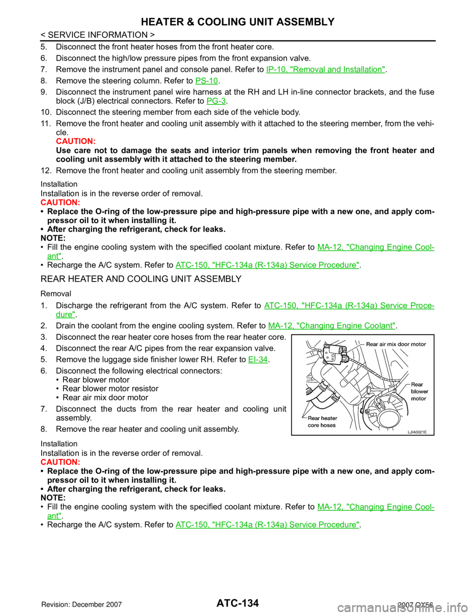
3. Disconnect the rear heater core hoses from the rear heater core.
4. Disconnect the rear A/C pipes from the rear expansion valve.
5. Remove the luggage side finisher lower RH. Refer to EI-34
.
6. Disconnect the following electrical connectors: • Rear blower motor
• Rear blower motor resistor
• Rear air mix door motor
7. Disconnect the ducts from the rear heater and cooling unit assembly.
8. Remove the rear heater and cooling unit assembly.
Installation
Installation is in the reverse order of removal.
CAUTION:
• Replace the O-ring of the low-pressure pipe and high-pressure pipe with a new one, and apply com-
pressor oil to it when installing it.
• After charging the refrigerant, check for leaks.
NOTE:
• Fill the engine cooling system with the s pecified coolant mixture. Refer to MA-12, "
Changing Engine Cool-
ant".
• Recharge the A/C system. Refer to ATC-150, "
HFC-134a (R-134a) Service Procedure".
LJIA0021E
Page 1412 of 3061

DTC P0300 - P0308 MULTIPLE CYLINDER MISFIRE, NO. 1 - 8 CYLINDER MIS-
FIRE
EC-329
< SERVICE INFORMATION >
C
D
E
F
G
H
I
J
K
L
MA
EC
N
P O
Check compression pressure. Refer to EM-64, "On-Vehicle Service".
OK or NG
OK >> GO TO 10.
NG >> Check pistons, piston rings, valves, valve seats and cylinder head gaskets.
10.CHECK FUEL PRESSURE
1. Install all removed parts.
2. Release fuel pressure to zero. Refer to EC-80, "
Fuel Pressure Check" .
3. Install fuel pressure gauge and check fuel pressure. Refer to EC-80, "
Fuel Pressure Check" .
OK or NG
OK >> GO TO 12.
NG >> GO TO 11.
11 .DETECT MALFUNCTIONING PART
Check the following.
• Fuel pump and circuit (Refer to EC-613
.)
• Fuel pressure regulator (Refer to EC-80, "
Fuel Pressure Check" .)
• Fuel lines
• Fuel filter for clogging
>> Repair or replace.
12.CHECK IGNITION TIMING
Check the following items. Refer to EC-71, "
Basic Inspection" .
OK or NG
OK >> GO TO 13.
NG >> Follow the EC-71, "
Basic Inspection" .
13.CHECK A/F SENSOR 1 INPUT SIGNAL
1. Turn ignition switch OFF.
2. Disconnect A/F sensor 1 harness connector.
3. Disconnect ECM harness connector.
4. Check harness continuity between the following terminals.
Refer to Wiring Diagram.At idling: Approximately 350 kPa (3.57 kg/cm
2 , 51 psi)
Items Specifications
Target idle speed 650 ± 50 rpm (in P or N position)
Ignition timing 15 ± 5° BTDC (in P or N position)
A/F sensor 1 terminal ECM terminal
Bank 1135
256
BBIA0376E
Page 1765 of 3061

EI-36
< SERVICE INFORMATION >
FLOOR TRIM
FLOOR TRIM
Removal and InstallationINFOID:0000000003533137
REMOVAL
1. Remove front seats. Refer to SE-83 .
• Remove subwoofer. Refer to AV-46, "
Removal and Installation" .
• Remove navigation display control unit. Refer to AV-145, "
Removal and Installation" .
2. Remove second row seats. Refer to SE-89, "
Removal and Installation" and SE-89, "Removal and Instal-
lation" , if equipped.
3. Remove third row rear seats. Refer to SE-95
.
4. Remove lower seat belt anchors. Refer to SB-3
.
5. Remove lower body side trim. Refer to EI-34
.
6. Remove luggage lower side finishers (left / right). Refer to EI-39
.
7. Remove kicking plates. Refer to EI-34
.
8. Remove center console. Refer to IP-10
.
9. Remove rear console, if equipped. Refer to IP-14, "
Disassembly and Assembly" .
10. Remove rear lower finisher. Refer to EI-39
.
11. Remove carpet.
12. Remove floor mat hook from front carpet.
INSTALLATION
Installation is in the reverse order of removal.
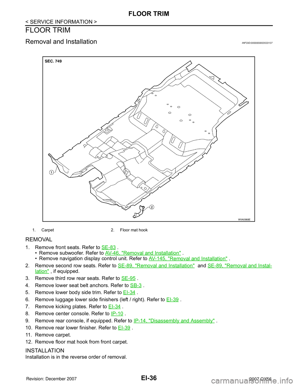
1. Carpet 2. Floor mat hook
WIIA0968E
Page 1802 of 3061

EM-32
< SERVICE INFORMATION >
FUEL INJECTOR AND FUEL TUBE
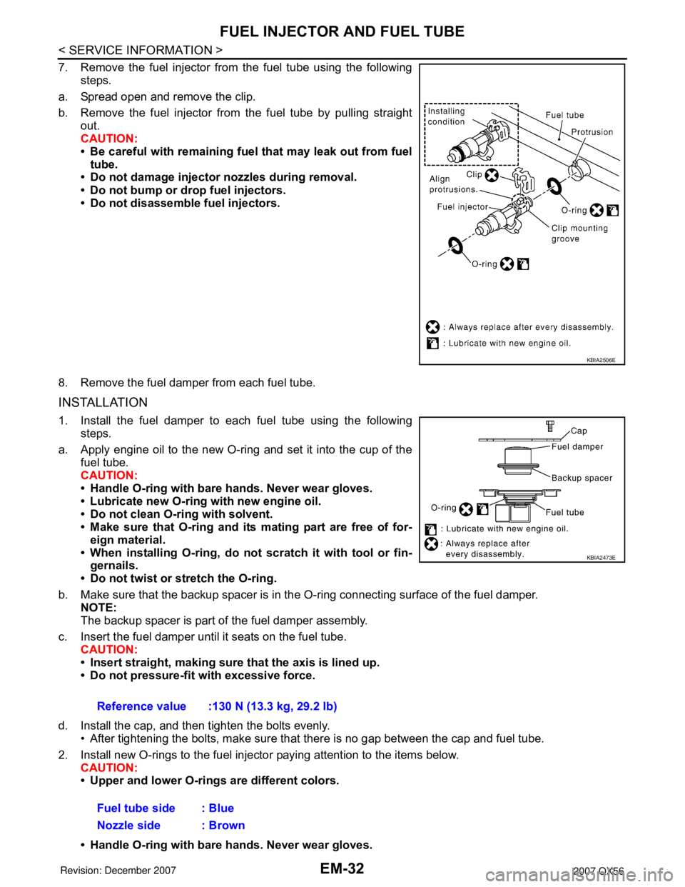
7. Remove the fuel injector from the fuel tube using the followingsteps.
a. Spread open and remove the clip.
b. Remove the fuel injector from the fuel tube by pulling straight out.
CAUTION:
• Be careful with remaining fuel that may leak out from fueltube.
• Do not damage injector nozzles during removal.
• Do not bump or drop fuel injectors.
• Do not disassemble fuel injectors.
8. Remove the fuel damper from each fuel tube.
INSTALLATION
1. Install the fuel damper to each fuel tube using the following steps.
a. Apply engine oil to the new O-ring and set it into the cup of the fuel tube.
CAUTION:
• Handle O-ring with bare hands. Never wear gloves.
• Lubricate new O-ring with new engine oil.
• Do not clean O-ring with solvent.
• Make sure that O-ring and its mating part are free of for-eign material.
• When installing O-ring, do not scratch it with tool or fin-
gernails.
• Do not twist or stretch the O-ring.
b. Make sure that the backup spacer is in the O-ring connecting surface of the fuel damper.
NOTE:
The backup spacer is part of the fuel damper assembly.
c. Insert the fuel damper until it seats on the fuel tube. CAUTION:
• Insert straight, making sure that the axis is lined up.
• Do not pressure-fit with excessive force.
d. Install the cap, and then tighten the bolts evenly. • After tightening the bolts, make sure that there is no gap between the cap and fuel tube.
2. Install new O-rings to the fuel injector paying attention to the items below. CAUTION:
• Upper and lower O-rings are different colors.
• Handle O-ring with bare hands. Never wear gloves.
KBIA2506E
Reference value :130 N (13.3 kg, 29.2 lb)
Fuel tube side : Blue
Nozzle side : Brown
KBIA2473E
Page 1838 of 3061

EM-68
< SERVICE INFORMATION >
CYLINDER HEAD
7. Remove the valve oil seal using Tool.
8. Replace the valve seat if necessary. Refer to EM-69, "
Inspection After Disassembly".
9. Replace the valve guide if necessary. Refer to EM-69, "
Inspection After Disassembly".
10. Remove the spark plug tube, as necessary.
• Remove the spark plug tube out of the cylinder head using suitable tool.
CAUTION:
• Do not damage the cylinder head.
• Do not remove the spark plug tube unless absolutely necessary. Once removed, the spark plug
tube will be deformed and cannot be reused.
ASSEMBLY
1. Install the valve guide if necessary. Refer to EM-69, "Inspection After Disassembly".
2. Install the valve seat if necessary. Refer to EM-69, "
Inspection After Disassembly".
3. Install the valve oil seal using Tool.
• Apply new engine oil on the new valve oil seal joint and seal
lip.
• Install the valve oil seal to the specified height "H".
4. Install the valves in their original position.
5. Install the valve spring seats.
6. Install the valve springs.
• Install the narrow pitch end (paint mark side) to the cylinder
head side.
7. Install the valve spring retainers.Tool number : KV10107902 (J-38959)
WBIA0478E
Tool number : KV10115600 (J-38958)
Height "H" (without valve spring installed)
Intake and exhaust : 14.3 - 14.9 mm (0.563 - 0.587 in)
WBIA0490E
SEM085D
Page 1842 of 3061

EM-72
< SERVICE INFORMATION >
CYLINDER HEAD
VALVE SEAT CONTACT
• After confirming that the dimensions of the valve guides and valves
are within specifications, perform this procedure.
• Apply prussian blue (or white lead) onto the contacting surface of
the valve seat to check the condition of the valve contact on the
surface.
• Check if the contact area band is continuous all around the circum-
ference.
• If not, grind to adjust the valve fit and check again. If the contacting
surface still has NG conditions even after the re-check, replace the
valve seat.
VALVE SEAT REPLACEMENT
When the valve seat is removed, replace it with oversized (0.5 mm, 0.020 in) valve seat.
1. Bore out the old seat until it collapses. Boring should not continue beyond the bottom face of the seat
recess in the cylinder head. Set the machine depth stop to ensure this.
2. Ream the cylinder head recess diameter for service valve seat.
• Be sure to ream in circles concentric to the valve guide center.
• This will enable valve seat to fit correctly.
3. Heat the cylinder head to 110° to 130°C (230° to 266°F) by
soaking it in heated oil.
4. Cool the valve seats well with dry ice. Force fit the valve seat into the cylinder head.
CAUTION:
• Avoid directly touching cold valve seats.
• Cylinder head contains heat. When working, wear protective equipment to avoid getting burned.
5. Finish the seat to the specified dimensions using suitable tool.
Refer to EM-103, "
Standard and Limit".
CAUTION:
When using valve seat cutter, firmly grip the cutter handle
with both hands. Then, press on the contacting surface all
around the circumference to cut in a single drive. Improper
pressure on the cutter or cutting many different times may
result in stage valve seat.
SBIA0322E
Oversize [0.5 mm (0.020 in)] (Service):
Intake : 38.500 - 38.516 mm (1.5157 - 1.5164 in)
Exhaust : 32.700 - 32.716 mm (1.2874 - 1.2880 in)
SEM795A
SEM008A
SEM934C
Page 2126 of 3061

IP-14
< SERVICE INFORMATION >
INSTRUMENT PANEL ASSEMBLY
1. Remove the instrument lower cover RH.
2. Remove glove box assembly screws, using power tool.
3. Disconnect glove box lamp.
4. Remove the lower instrument panel RH and glove box.
Installation
Installation is in the reverse order of removal.
CENTER CONSOLE
Removal
1. Move front seats forward.
2. Disconnect battery negative terminal.
3. Remove control device. Refer to AT-207
.
4. Remove glove box assembly. Refer to IP-10
.
5. Remove center console lower cover RH.
6. Remove console cover RH screws.
7. Remove center console lower cover LH.
8. Remove console cover LH screws.
9. Disconnect center console electrical connectors.
10. Remove center console assembly in a rearward direction.
Installation
Installation is in the reverse order of removal.
REAR CONSOLE
Removal
1. Remove cup holder insert.
2. Release latch and remove rear console assembly.
Installation
Installation is in the reverse order of removal.
Disassembly and AssemblyINFOID:0000000003533148
LOWER INSTRUMENT PANEL RH AND GLOVE BOX
LLIA0072E
Page 2554 of 3061

RF-22
< SERVICE INFORMATION >
SUNROOF
SUNROOF UNIT
Removal
CAUTION:
• Always work with a helper.
• When taking sunroof unit out, use shop cloths to protect the seats and trim from damage.
• After installing the sunroof unit and glass lid assembly, check gap adjustment to make sure there is
no malfunction.
1. Remove headlining. Refer to EI-37
.
2. Remove the sunroof glass lid assembly. Refer to "GLASS LID ASSEMBLY".
3. Remove overhead console bracket.
4. Disconnect front and rear drain hoses.
5. Remove front sunroof frame assembly bolts.
6. Remove rear sunroof bracket bolts.
7. Remove the sunroof frame assembly side bolts, then the sunroof unit.
Installation
1. Position the sunroof frame assembly and install the side bolts.
2. Install the sunroof brackets and bolts.
3. Install the front sunroof frame assembly bolts.
4. Connect front and rear drain hoses.
5. Install the overhead console bracket.
6. Install the sunroof glass lid assembly. Refer to "GLASS LID ASSEMBLY".
NOTE:
Adjust sunroof glass lid assembly gap and height, refer to RF-20, "
Fitting Adjustment".
7. Install headlining. Refer to EI-37
.
GLASS LID ASSEMBLY
Removal
1. Open sunshade assembly.
NOTE:
Be sure glass lid assembly is fully closed.
2. Remove side cover LH and RH.
3. Remove the glass lid assembly screws at the sunroof frame
assembly.
4. Remove the glass lid assembly.
Installation
1. Position glass lid assembly to sunroof frame assembly.
2. Install glass lid assembly screws.
NOTE:
First tighten left front screw, then right rear to prevent movement while tightening the remaining screws.
1. Glass lid assembly 2. Wind deflector 3. Rear drain hoses
4. Shade stoppers 5. Sunroof bracket 6. Sunshade assembly
7. Front drain hoses 8. Sunroof motor assembly 9. Sunroof frame assembly
10. Overhead console bracket 11. Side cover LH 12. Side cover RH
WIIA0252E
Page 2626 of 3061

RSU-36
< SERVICE INFORMATION >
REAR LOWER LINK & COIL SPRING
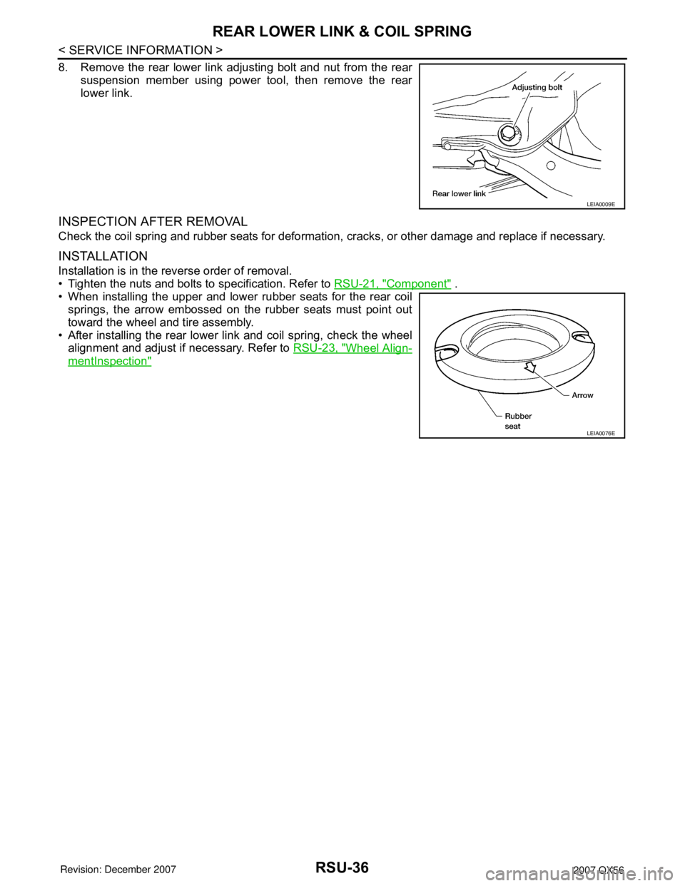
8. Remove the rear lower link adjusting bolt and nut from the rear
suspension member using power tool, then remove the rear
lower link.
INSPECTION AFTER REMOVAL
Check the coil spring and rubber seats for deformation, cracks, or other damage and replace if necessary.
INSTALLATION
Installation is in the reverse order of removal.
• Tighten the nuts and bolts to specification. Refer to RSU-21, "
Component" .
• When installing the upper and lower rubber seats for the rear coil
springs, the arrow embossed on the rubber seats must point out
toward the wheel and tire assembly.
• After installing the rear lower link and coil spring, check the wheel
alignment and adjust if necessary. Refer to RSU-23, "
Wheel Align-
mentInspection"
LEIA0009E
LEIA0076E
Page 2644 of 3061

SB-10
< SERVICE INFORMATION >
SEAT BELTS
4. Remove push pin (2) and release elastic ban (3) from seat
frame (1). Repeat for opposite seat.
•⇐: Vehicle front
5. Partially lift seatback upright, then remove seat belt buckle (2)
from between hinge cover (1) and seat cushion side facing (3).
Repeat for LH seat.
•⇐: Vehicle front
Installation
Installation is in the reverse order of removal.
• Raise and lock both seats in the full upright position to check for abnormal noises or binding.
Seat Belt InspectionINFOID:0000000003532846
AFTER A COLLISION
WARNING:
Inspect all seat belt assemblies including retractors and attaching hardware after any collision.
NISSAN recommends that all seat belt assemblies in use during a collision be replaced unless the col-
lision was minor and the belts show no damage and continue to operate properly. Failure to do so
could result in serious personal injury in an accident. Seat belt assemblies not in use during a colli-
sion should also be replaced if either damage or improper operation is noted. Seat belt pre-tensioners
should be replaced even if the seat belts are not in use during a frontal collision in which the air bags
are deployed.
Replace any seat belt retractor and belt assembly (including anchor bolts) if:
• The seat belt was in use at the time of a collision (except for minor collisions and the belts, retractors and
buckles show no damage and continue to operate properly).
• The seat belt was damaged in an accident. (i.e. torn webbing, bent retractor or guide).
• The seat belt attaching point was damaged in an accident. Inspect the seat belt attaching area for damage
or distortion and repair as necessary before installing a new seat belt retractor and belt assembly.
• Anchor bolts are deformed or worn out.
• The seat belt pre-tensioner should be replaced even if the seat belts are not in use during the collision in
which the air bags are deployed.
PRELIMINARY CHECKS
1. Check the seat belt warning lamp/chime for proper operation as follows:
a. Switch ignition ON. The seat belt warning lamp should illuminate. Also, the seat belt warning chime should
sound for about seven seconds.
b. Fasten drivers seat belt. The seat belt warning lamp should go out and the chime (if sounding) should
stop.
2. If the air bag warning lamp is blinking, conduct self-diagnosis using CONSULT-II, and air bag warning
lamp. Refer to SRS-20, "
SRS Operation Check".
3. Check that the seat belt retractor and belt assembly, seat belt anchor and buckle bolts are securely
attached.
LHIA0105E
LHIA0106E