wheel torque INFINITI QX56 2007 Factory Service Manual
[x] Cancel search | Manufacturer: INFINITI, Model Year: 2007, Model line: QX56, Model: INFINITI QX56 2007Pages: 3061, PDF Size: 64.56 MB
Page 107 of 3061
A/T CONTROL SYSTEM
AT-37
< SERVICE INFORMATION >
D
E
F
G
H
I
J
K
L
MA
B
AT
N
O
P
When shifting from the lock-up released state to the lock-up applied state, the current output to the torque con-
verter clutch solenoid is controlled with the TCM. In this way, when shifting to the lock-up applied state, the
torque converter clutch is temporarily set to the half-clutched state to reduce the shock.
Half-clutched State
• The current output from the TCM to the torque converter clutch solenoid is varied to gradually increase the
torque converter clutch solenoid pressure.
In this way, the lock-up apply pressure gradually rises and while the torque converter clutch piston is put into
half-clutched status, the torque converter clutch piston operating pressure is increased and the coupling is
completed smoothly.
Slip Lock-up Control
• In the slip region, the torque converter clutch solenoid current is controlled with the TCM to put it into the
half-clutched state. This absorbs the engine torque fluctuation and lock-up operates from low speed.
This raises the fuel efficiency for 4th and 5th gears at both low speed and when the accelerator has a low
degree of opening.
Engine Brake ControlINFOID:0000000003532236
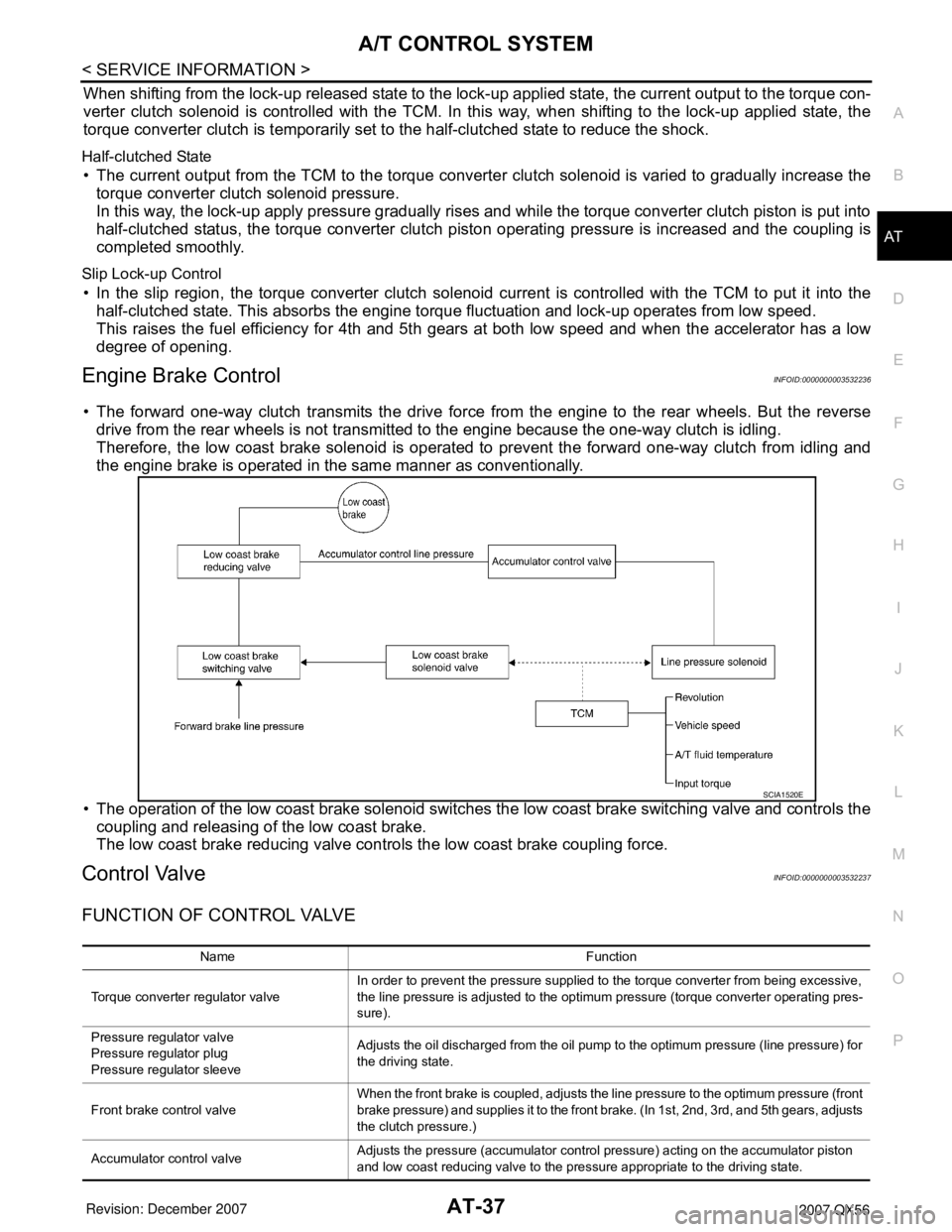
• The forward one-way clutch transmits the drive force from the engine to the rear wheels. But the reverse
drive from the rear wheels is not transmitted to the engine because the one-way clutch is idling.
Therefore, the low coast brake solenoid is operated to prevent the forward one-way clutch from idling and
the engine brake is operated in the same manner as conventionally.
• The operation of the low coast brake solenoid switches the low coast brake switching valve and controls the
coupling and releasing of the low coast brake.
The low coast brake reducing valve controls the low coast brake coupling force.
Control ValveINFOID:0000000003532237
FUNCTION OF CONTROL VALVE
SCIA1520E
Name Function
Torque converter regulator valveIn order to prevent the pressure supplied to the torque converter from being excessive,
the line pressure is adjusted to the optimum pressure (torque converter operating pres-
sure).
Pressure regulator valve
Pressure regulator plug
Pressure regulator sleeveAdjusts the oil discharged from the oil pump to the optimum pressure (line pressure) for
the driving state.
Front brake control valveWhen the front brake is coupled, adjusts the line pressure to the optimum pressure (front
brake pressure) and supplies it to the front brake. (In 1st, 2nd, 3rd, and 5th gears, adjusts
the clutch pressure.)
Accumulator control valveAdjusts the pressure (accumulator control pressure) acting on the accumulator piston
and low coast reducing valve to the pressure appropriate to the driving state.
Page 528 of 3061
ATC-158
< SERVICE INFORMATION >
REFRIGERANT LINES
BREAK-IN OPERATION
When replacing compressor clutch assembly, always conduct the break-in operation. This is done by engag-
ing and disengaging the clutch about 30 times. Break-in operation raises the level of transmitted torque.
Removal and Installation for Low-Pressure Flexible HoseINFOID:0000000003533295
REMOVAL
1. Remove the engine room cover using power tools.
2. Remove the engine air cleaner and air ducts. Refer to EM-15
.
3. Remove the cowl top extension. Refer to EI-17
.
4. Discharge the refrigerant. Refer to ATC-150, "
HFC-134a (R-134a) Service Procedure".
CAUTION:
Cap or wrap the joint of the pipe with suitable mate rial such as vinyl tape to avoid the entry of air.
5. Remove the low-pressure flexible hose.
INSTALLATION
Installation is in the reverse order of removal.
Refer to ATC-152, "
Component".
CAUTION:
• Replace the O-ring of the low-pr essure flexible hose with a new one, then apply compressor oil to it
when installing it.
• After charging refrigerant, check for leaks.
Removal and Installation for High-pressure Flexible HoseINFOID:0000000003533296
REMOVAL
1. Remove the engine under cover.
2. Remove the engine air cleaner and air ducts. Refer to EM-15
.
3. Discharge the refrigerant. Refer to ATC-150, "
HFC-134a (R-134a) Service Procedure".
4. Remove the high-pressure flexible hose. CAUTION:
Cap or wrap the joint of the pipe with suitable mate rial such as vinyl tape to avoid the entry of air.
INSTALLATION
Installation is in the reverse order of removal.
Refer to ATC-152, "
Component".
CAUTION:
• Replace the O-ring of the high-pressure flexible hose with a new one, then apply compressor oil to it
when installing it.
• After charging refrigerant, check for leaks.
Removal and Installation for High-pressure PipeINFOID:0000000003533297
REMOVAL
1. Remove the cowl top extension. Refer to EI-17.
2. Disconnect the battery negative terminal and positive battery terminal.
3. Reposition the IPDM E/R aside.
4. Remove the front right wheel and tire assembly. Refer to WT-7, "
Rotation".
5. Position aside the front floor insulator.
6. Discharge the refrigerant. Refer to ATC-150, "
HFC-134a (R-134a) Service Procedure".
7. Remove the low-pressure pipe. Refer to ATC-159, "
Removal and Installation for Low-Pressure Pipe".
8. Remove the high-pressure pipe. CAUTION:
Cap or wrap the joint of the pipe with suitable mate rial such as vinyl tape to avoid the entry of air.
INSTALLATION
Installation is in the reverse order of removal.
Page 900 of 3061
BR-2
< SERVICE INFORMATION >
PRECAUTIONS
SERVICE INFORMATION
PRECAUTIONS
Precaution for Supplemental Restraint System (SRS) "AIR BAG" and "SEAT BELT
PRE-TENSIONER"
INFOID:0000000003532717
The Supplemental Restraint System such as “AIR BAG” and “SEAT BELT PRE-TENSIONER”, used along
with a front seat belt, helps to reduce the risk or severity of injury to the driver and front passenger for certain
types of collision. This system includes seat belt switch inputs and dual stage front air bag modules. The SRS
system uses the seat belt switches to determine the front air bag deployment, and may only deploy one front
air bag, depending on the severity of a collision and whether the front occupants are belted or unbelted.
Information necessary to service the system safely is included in the SRS and SB section of this Service Man-
ual.
WARNING:
• To avoid rendering the SRS inoperative, which could increase the risk of personal injury or death in
the event of a collision which would result in air bag inflation, all maintenance must be performed by
an authorized NISSAN/INFINITI dealer.
• Improper maintenance, including incorrect removal and installation of the SRS, can lead to personal
injury caused by unintentional activation of the system. For removal of Spiral Cable and Air Bag
Module, see the SRS section.
• Do not use electrical test equipment on any circuit related to the SRS unless instructed to in this
Service Manual. SRS wiring harnesses can be identified by yellow and/or orange harnesses or har-
ness connectors.
Precaution for Brake SystemINFOID:0000000003532718
• Always use recommended brake fluid. Refer to MA-10 .
• Do not reuse drained brake fluid.
• Be careful not to splash brake fluid on painted areas.
• To clean or wash all parts of master cylinder, disc brake caliper and wheel cylinder, use clean brake fluid.
• Do not use mineral oils such as gasoline or kerosene. They will ruin rubber parts of the hydraulic system.
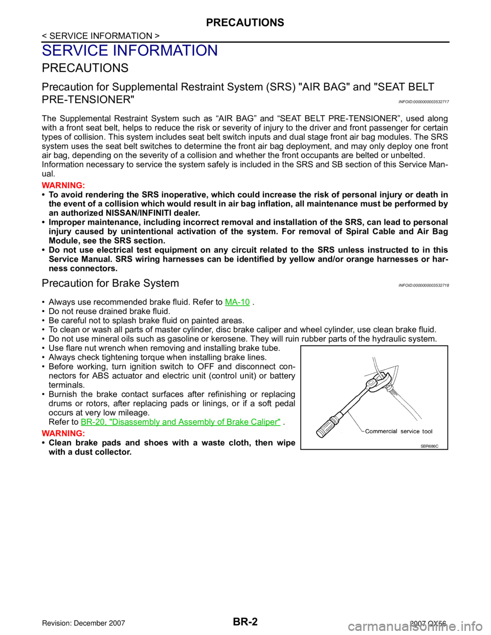
• Use flare nut wrench when removing and installing brake tube.
• Always check tightening torque when installing brake lines.
• Before working, turn ignition switch to OFF and disconnect con-
nectors for ABS actuator and electric unit (control unit) or battery
terminals.
• Burnish the brake contact surfaces after refinishing or replacing
drums or rotors, after replacing pads or linings, or if a soft pedal
occurs at very low mileage.
Refer to BR-20, "
Disassembly and Assembly of Brake Caliper" .
WARNING:
• Clean brake pads and shoes with a waste cloth, then wipe
with a dust collector.
SBR686C
Page 907 of 3061

BRAKE FLUID
BR-9
< SERVICE INFORMATION >
C
D
E
G
H
I
J
K
L
MA
B
BR
N
O
P
4. With brake pedal depressed, loosen bleed valve to let the air out, and then tighten it immediately.
5. Repeat steps 3 and 4 until no more air comes out.
6. Tighten bleed valve to the specified torque. Refer to BR-18, "
Component" (front disc brake), BR-24,
"Exploded View" (rear disc brake).
7. Repeat steps 2 through 6 at each wheel, with master cylinder reservoir tank filled at least half way, bleed
air in order from the front left, rear left, and front right bleed valves.
Page 920 of 3061
BR-22
< SERVICE INFORMATION >
FRONT DISC BRAKE
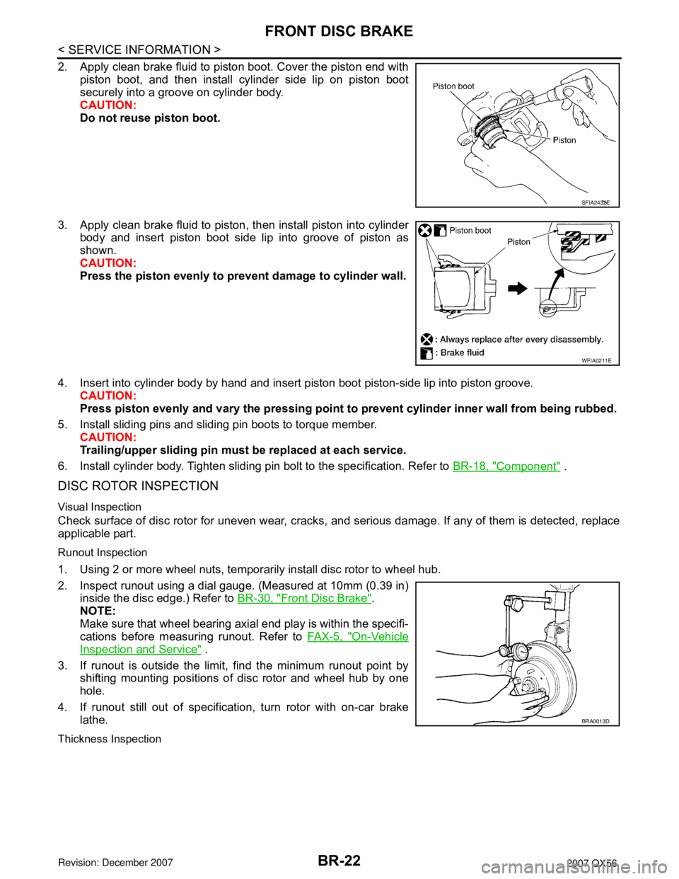
2. Apply clean brake fluid to piston boot. Cover the piston end with
piston boot, and then install cylinder side lip on piston boot
securely into a groove on cylinder body.
CAUTION:
Do not reuse piston boot.
3. Apply clean brake fluid to piston, then install piston into cylinder
body and insert piston boot side lip into groove of piston as
shown.
CAUTION:
Press the piston evenly to prevent damage to cylinder wall.
4. Insert into cylinder body by hand and insert piston boot piston-side lip into piston groove.
CAUTION:
Press piston evenly and vary the pressing point to prevent cylinder inner wall from being rubbed.
5. Install sliding pins and sliding pin boots to torque member.
CAUTION:
Trailing/upper sliding pin must be replaced at each service.
6. Install cylinder body. Tighten sliding pin bolt to the specification. Refer to BR-18, "
Component" .
DISC ROTOR INSPECTION
Visual Inspection
Check surface of disc rotor for uneven wear, cracks, and serious damage. If any of them is detected, replace
applicable part.
Runout Inspection
1. Using 2 or more wheel nuts, temporarily install disc rotor to wheel hub.
2. Inspect runout using a dial gauge. (Measured at 10mm (0.39 in)
inside the disc edge.) Refer to BR-30, "
Front Disc Brake".
NOTE:
Make sure that wheel bearing axial end play is within the specifi-
cations before measuring runout. Refer to FAX-5, "
On-Vehicle
Inspection and Service" .
3. If runout is outside the limit, find the minimum runout point by
shifting mounting positions of disc rotor and wheel hub by one
hole.
4. If runout still out of specification, turn rotor with on-car brake
lathe.
Thickness Inspection
SFIA2432E
WFIA0211E
BRA0013D
Page 934 of 3061
![INFINITI QX56 2007 Factory Service Manual BRC-6
< SERVICE INFORMATION >[VDC/TCS/ABS]
PREPARATION
PREPARATION
Special Service ToolINFOID:0000000003532766
The actual shapes of Kent-Moore tools may differ from those of special service tools illu INFINITI QX56 2007 Factory Service Manual BRC-6
< SERVICE INFORMATION >[VDC/TCS/ABS]
PREPARATION
PREPARATION
Special Service ToolINFOID:0000000003532766
The actual shapes of Kent-Moore tools may differ from those of special service tools illu](/img/42/57029/w960_57029-933.png)
BRC-6
< SERVICE INFORMATION >[VDC/TCS/ABS]
PREPARATION
PREPARATION
Special Service ToolINFOID:0000000003532766
The actual shapes of Kent-Moore tools may differ from those of special service tools illustrated here.
Commercial Service ToolINFOID:0000000003532767
Tool number
(Kent-Moore No.)
Tool nameDescription
—
(J-45741)
ABS active wheel sensor testerChecking operation of ABS active wheel sen-
sors
WFIA0101E
Tool nameDescription
1. Flare nut crowfoot
2. Torque wrenchRemoving and installing brake piping
a: 10mm (0.39 in)/12mm (0.47 in)
S-NT360
Page 936 of 3061
![INFINITI QX56 2007 Factory Service Manual BRC-8
< SERVICE INFORMATION >[VDC/TCS/ABS]
SYSTEM DESCRIPTION
ABS Function
INFOID:0000000003532769
• The Anti-Lock Brake System detects wheel revolution while braking and improves handling stability INFINITI QX56 2007 Factory Service Manual BRC-8
< SERVICE INFORMATION >[VDC/TCS/ABS]
SYSTEM DESCRIPTION
ABS Function
INFOID:0000000003532769
• The Anti-Lock Brake System detects wheel revolution while braking and improves handling stability](/img/42/57029/w960_57029-935.png)
BRC-8
< SERVICE INFORMATION >[VDC/TCS/ABS]
SYSTEM DESCRIPTION
ABS Function
INFOID:0000000003532769
• The Anti-Lock Brake System detects wheel revolution while braking and improves handling stability during
sudden braking by electrically preventing wheel lockup. Maneuverability is also improved for avoiding obsta-
cles.
• If the electrical system malfunctions, the Fail-Safe function is activated, the ABS becomes inoperative and
the ABS warning lamp turns on.
• The electrical system can be diagnosed using CONSULT-II.
• During ABS operation, the brake pedal may vibrate lightly and a mechanical noise may be heard. This is
normal.
• Just after starting the vehicle, the brake pedal may vibrate or a motor operating noise may be heard from
engine compartment. This is a normal status of operation check.
• Stopping distance may be longer than that of vehicles without ABS when vehicle drives on rough, gravel, or
snow-covered (fresh, deep snow) roads.
EBD FunctionINFOID:0000000003532770
• Electronic Brake Distribution is a function that detects subtle slippages between the front and rear wheels
during braking, and it improves handling stability by electronically controlling the brake fluid pressure which
results in reduced rear wheel slippage.
• If the electrical system malfunctions, the Fail-Safe function is activated, the EBD and ABS become inopera-
tive, and the ABS warning lamp and BRAKE warning lamp are turned on.
• The electrical system can be diagnosed using CONSULT-II.
• During EBD operation, the brake pedal may vibrate lightly and a mechanical noise may be heard. This is
normal.
• Just after starting the vehicle, the brake pedal may vibrate or a motor operating noise may be heard from
engine compartment. This is a normal status of operation check.
TCS FunctionINFOID:0000000003532771
• Spinning of the drive wheels is detected by the ABS actuator and electric unit (control unit) using inputs from
the wheel speed sensors. If wheel spin occurs, the drive wheel right and left brake fluid pressure control and
engine fuel cut are activated while the throttle value is restricted to reduce the engine torque and decrease
the amount of wheel spin. In addition, the throttle opening is controlled to achieve the optimum engine
torque.
• Depending on road condition, the vehicle may have a sluggish feel. This is normal, because optimum trac-
tion has the highest priority during TCS operation.
• TCS may be activated during sudden vehicle acceleration, wide open throttle acceleration, sudden transmis-
sion shifts or when the vehicle is driven on a road with a varying surface friction coefficient.
• The SLIP indicator lamp flashes to inform the driver of TCS operation.
VDC FunctionINFOID:0000000003532772
• In addition to the ABS/TCS function, the driver steering amount and brake operation amount are detected
from the steering angle sensor and front and rear pressure sensors, and the vehicle's driving status (amount
of under steering/over steering) is determined using inputs from the yaw rate sensor/side G sensor, wheel
speed sensors, etc. and this information is used to improve vehicle stability by controlling the braking and
engine torque application to the wheels.
• The SLIP indicator lamp flashes to inform the driver of VDC operation.
• During VDC operation, the vehicle body and brake pedal may vibrate lightly and a mechanical noise may be
heard. This is normal.
• The ABS warning lamp, VDC OFF indicator lamp and SLIP indicator lamp may turn on when the vehicle is
subject to strong shaking or large vibration, such as when the vehicle is on a turn table or a ship while the
engine is running or on a steep slope. In this case, restart the engine on a normal road and if the ABS warn-
ing lamp, VDC OFF indicator lamp and SLIP indicator lamp turn off, there is no problem.
Fail-Safe FunctionINFOID:0000000003532773
CAUTION:
If the Fail-Safe function is activated, perform the Self Diagnosis for ABS/TCS/VDC system.
ABS/EBD SYSTEM
Page 1232 of 3061
DTC P0011, P0021 IVT CONTROL
EC-149
< SERVICE INFORMATION >
C
D
E
F
G
H
I
J
K
L
MA
EC
N
P O
DTC P0011, P0021 IVT CONTROL
DescriptionINFOID:0000000003531648
SYSTEM DESCRIPTION
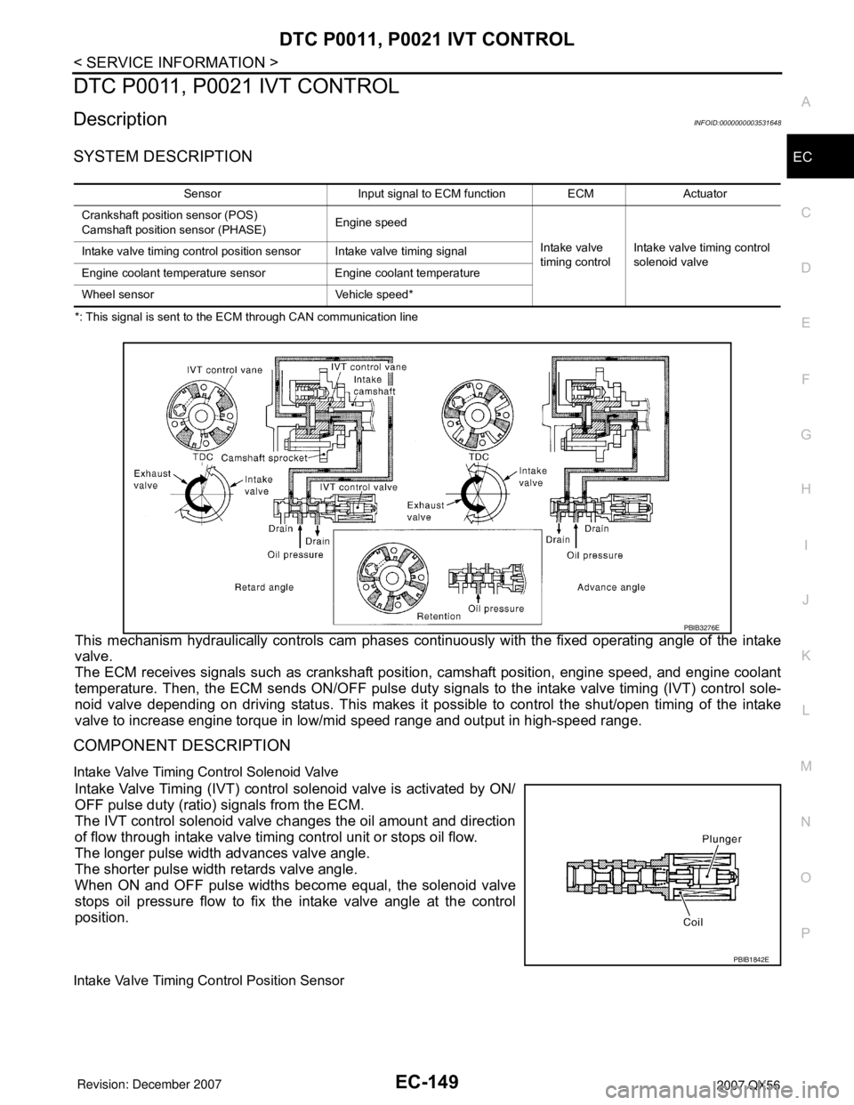
*: This signal is sent to the ECM through CAN communication line
This mechanism hydraulically controls cam phases continuously with the fixed operating angle of the intake
valve.
The ECM receives signals such as crankshaft position, camshaft position, engine speed, and engine coolant
temperature. Then, the ECM sends ON/OFF pulse duty signals to the intake valve timing (IVT) control sole-
noid valve depending on driving status. This makes it possible to control the shut/open timing of the intake
valve to increase engine torque in low/mid speed range and output in high-speed range.
COMPONENT DESCRIPTION
Intake Valve Timing Control Solenoid Valve
Intake Valve Timing (IVT) control solenoid valve is activated by ON/
OFF pulse duty (ratio) signals from the ECM.
The IVT control solenoid valve changes the oil amount and direction
of flow through intake valve timing control unit or stops oil flow.
The longer pulse width advances valve angle.
The shorter pulse width retards valve angle.
When ON and OFF pulse widths become equal, the solenoid valve
stops oil pressure flow to fix the intake valve angle at the control
position.
Intake Valve Timing Control Position Sensor
Sensor Input signal to ECM function ECM Actuator
Crankshaft position sensor (POS)
Camshaft position sensor (PHASE)Engine speed
Intake valve
timing controlIntake valve timing control
solenoid valve Intake valve timing control position sensor Intake valve timing signal
Engine coolant temperature sensor Engine coolant temperature
Wheel sensor Vehicle speed*
PBIB3276E
PBIB1842E
Page 1891 of 3061
WHEEL HUB
FAX-5
< SERVICE INFORMATION >
C
E
F
G
H
I
J
K
L
MA
B
FA X
N
O
P
WHEEL HUB
On-Vehicle Inspection and ServiceINFOID:0000000003532614
Make sure the mounting conditions (looseness, backlash) of each component and component status (wear,
damage) are normal.
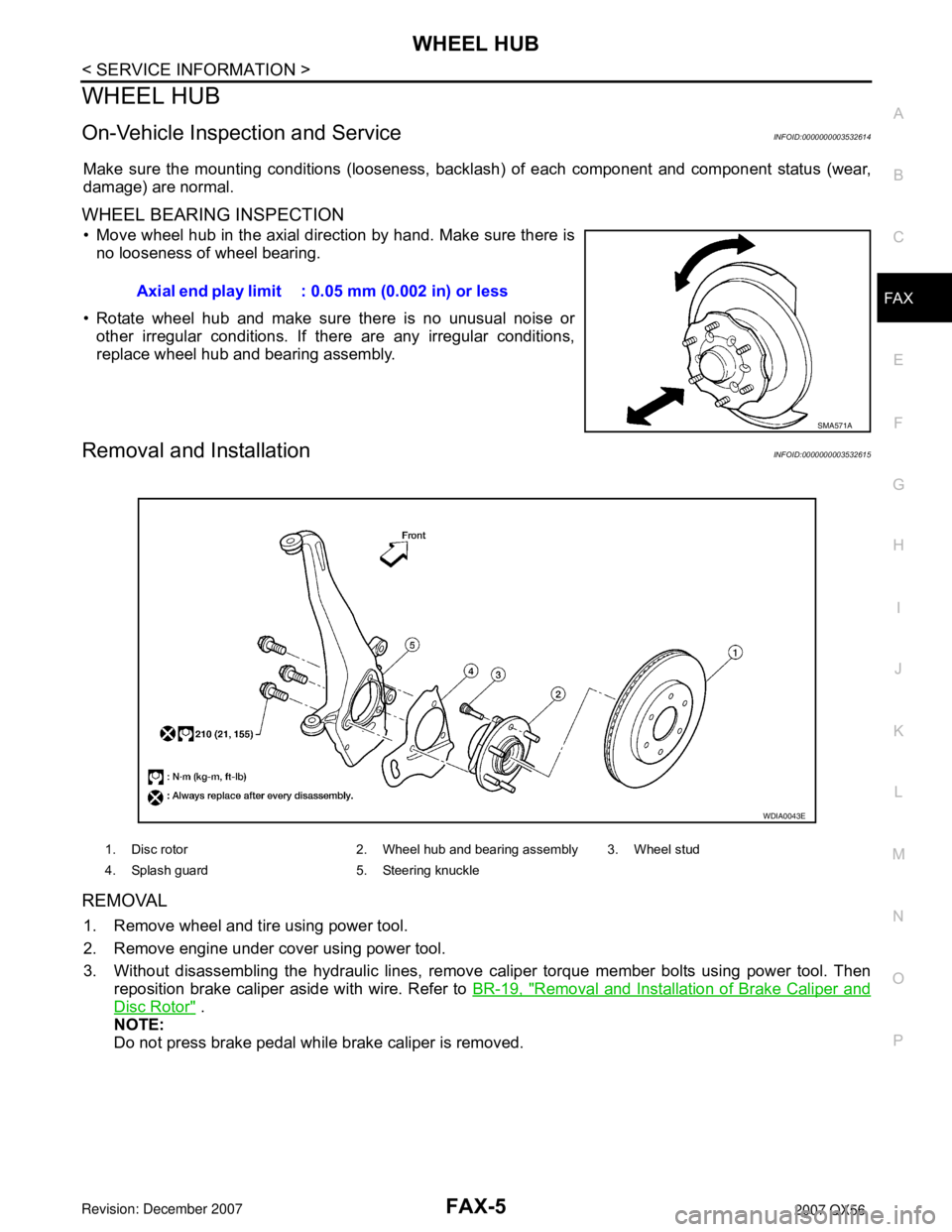
WHEEL BEARING INSPECTION
• Move wheel hub in the axial direction by hand. Make sure there is
no looseness of wheel bearing.
• Rotate wheel hub and make sure there is no unusual noise or
other irregular conditions. If there are any irregular conditions,
replace wheel hub and bearing assembly.
Removal and InstallationINFOID:0000000003532615
REMOVAL
1. Remove wheel and tire using power tool.
2. Remove engine under cover using power tool.
3. Without disassembling the hydraulic lines, remove caliper torque member bolts using power tool. Then
reposition brake caliper aside with wire. Refer to BR-19, "
Removal and Installation of Brake Caliper and
Disc Rotor" .
NOTE:
Do not press brake pedal while brake caliper is removed.Axial end play limit : 0.05 mm (0.002 in) or less
SMA571A
1. Disc rotor 2. Wheel hub and bearing assembly 3. Wheel stud
4. Splash guard 5. Steering knuckle
WDIA0043E
Page 1952 of 3061
FSU-6
< SERVICE INFORMATION >
ON-VEHICLE SERVICE
ON-VEHICLE SERVICE
Front Suspension PartsINFOID:0000000003532636
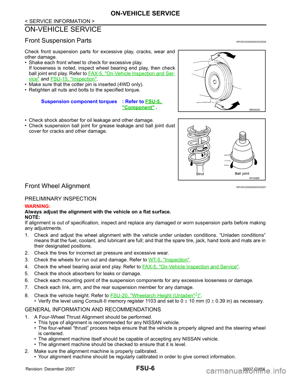
Check front suspension parts for excessive play, cracks, wear and
other damage.
• Shake each front wheel to check for excessive play.
If looseness is noted, inspect wheel bearing end play, then check
ball joint end play. Refer to FA X - 5 , "
On-Vehicle Inspection and Ser-
vice" and FSU-15, "Inspection".
• Make sure that the cotter pin is inserted (4WD only).
• Retighten all nuts and bolts to the specified torque.
• Check shock absorber for oil leakage and other damage.
• Check suspension ball joint for grease leakage and ball joint dust
cover for cracks and other damage.
Front Wheel AlignmentINFOID:0000000003532637
PRELIMINARY INSPECTION
WARNING:
Always adjust the alignment with the vehicle on a flat surface.
NOTE:
If alignment is out of specification, inspect and replace any damaged or worn suspension parts before making
any adjustments.
1. Check and adjust the wheel alignment with the vehicle under unladen conditions. “Unladen conditions”
means that the fuel, coolant, and lubricant are full; and that the spare tire, jack, hand tools and mats are in
their designated positions.
2. Check the tires for incorrect air pressure and excessive wear.
3. Check the wheels for run out and damage. Refer to WT-5, "
Inspection".
4. Check the wheel bearing axial end play. Refer to FA X - 5 , "
On-Vehicle Inspection and Service".
5. Check the shock absorbers for leaks or damage.
6. Check each mounting point of the suspension components for any excessive looseness or damage.
7. Check each link, arm, and the rear suspension member for any damage.
8. Check the vehicle height. Refer to FSU-20, "
Wheelarch Height (Unladen*1)".
• Verify the level using Consult-II memory register 1103 and set to 0 ± 10 mm (0 ± 0.39 in) as necessary.
GENERAL INFORMATION AND RECOMMENDATIONS
1. A Four-Wheel Thrust Alignment should be performed.
• This type of alignment is recommended for any NISSAN vehicle.
• The four-wheel “thrust” process helps ensure that the vehicle is properly aligned and the steering wheel
is centered.
• The alignment machine itself should be capable of accepting any NISSAN vehicle.
• The alignment machine should be checked to ensure that it is level.
2. Make sure the alignment machine is properly calibrated.
• Your alignment machine should be regularly calibrated in order to give correct information.Suspension component torques : Refer to FSU-5,
"Component" . SMA525A
SFA392B