weight INFINITI QX56 2007 Factory Service Manual
[x] Cancel search | Manufacturer: INFINITI, Model Year: 2007, Model line: QX56, Model: INFINITI QX56 2007Pages: 3061, PDF Size: 64.56 MB
Page 26 of 3061
![INFINITI QX56 2007 Factory Service Manual LASER BEAM AIMING ADJUSTMENT
ACS-13
< SERVICE INFORMATION >[ICC]
C
D
E
F
G
H
I
J
L
MA
B
ACS
N
O
P
2. Adjust the height of the target stand so that the point of the trian-
gle aims above the center of INFINITI QX56 2007 Factory Service Manual LASER BEAM AIMING ADJUSTMENT
ACS-13
< SERVICE INFORMATION >[ICC]
C
D
E
F
G
H
I
J
L
MA
B
ACS
N
O
P
2. Adjust the height of the target stand so that the point of the trian-
gle aims above the center of](/img/42/57029/w960_57029-25.png)
LASER BEAM AIMING ADJUSTMENT
ACS-13
< SERVICE INFORMATION >[ICC]
C
D
E
F
G
H
I
J
L
MA
B
ACS
N
O
P
2. Adjust the height of the target stand so that the point of the trian-
gle aims above the center of the ICC sensor.
ADJUSTING THE POSITION OF THE TARGET BOARD STRING
1. Attach a scale or straightedge (at least 350 mm [14 in] or
longer).
2. Suspend a string with a weight on the end 218 mm
(8.6 in) to the left side of the target board center.
POSITIONING THE TARGET
1. Suspend a string with weights on each end over the centerline of the vehicle. The string should lay over
the center of the front and back bumpers. Mark these centerpoints on the ground at each weight.
2. Connect the two center points using a string. Extend the string
an additional 5 m (16 ft) beyond the front centerpoint and mark
the floor. Position the target board weight on this mark.
3. Relocate the suspended string from the left side of the target board to the center of the target board. Mark
this point on the ground.
WKIA2039E
SKIA1211E
WKIA2040E
WKIA1851E
Page 79 of 3061
PRECAUTIONS
AT-9
< SERVICE INFORMATION >
D
E
F
G
H
I
J
K
L
MA
B
AT
N
O
P
•After performing each TROUBLE DIAGNOSIS, perform “DTC
(Diagnostic Trouble Code) CONFIRMATION PROCEDURE”.
If the repair is completed the DTC should not be displayed in
the “DTC CONFIRMATION PROCEDURE”.
• Always use the specified brand of ATF. Refer to MA-10
.
• Use paper rags not cloth rags during work.
• After replacing the ATF, dispose of the waste oil using the methods prescribed by law, ordinance, etc.
• Before proceeding with disassembly, thoroughly clean the outside of the transmission. It is important to pre-
vent the internal parts from becoming contaminated by dirt or other foreign matter.
• Disassembly should be done in a clean work area.
• Use lint-free cloth or towels for wiping parts clean. Common shop rags can leave fibers that could interfere
with the operation of the transmission.
• Place disassembled parts in order for easier and proper assembly.
• All parts should be carefully cleaned with a general purpose, non-flammable solvent before inspection or
reassembly.
• Gaskets, seals and O-rings should be replaced any time the transmission is disassembled.
• It is very important to perform functional tests whenever they are indicated.
• The valve body contains precision parts and requires extreme care when parts are removed and serviced.
Place disassembled valve body parts in order for easier and proper assembly. Care will also prevent springs
and small parts from becoming scattered or lost.
• Properly installed valves, sleeves, plugs, etc. will slide along bores in valve body under their own weight.
• Before assembly, apply a coat of recommended ATF to all parts. Apply petroleum jelly to protect O-rings and
seals, or hold bearings and washers in place during assembly. Do not use grease.
• Extreme care should be taken to avoid damage to O-rings, seals and gaskets when assembling.
• Clean or replace ATF cooler if excessive foreign material is found in oil pan or clogging strainer. Refer to AT-
15, "A/T Fluid Cooler Cleaning".
• After overhaul, refill the transmission with new ATF.
• When the A/T drain plug is removed, only some of the fluid is drained. Old A/T fluid will remain in torque con-
verter and ATF cooling system.
Always follow the procedures under “Changing A/T Fluid” in the AT section when changing A/T fluid. Refer to
AT-13, "
Changing Automatic Transmission Fluid (ATF)", AT-13, "Checking Automatic Transmission Fluid
(ATF)".
Service Notice or PrecautionINFOID:0000000003532221
ATF COOLER SERVICE
If A/T fluid contains frictional material (clutches, bands, etc.), or if an A/T is repaired, overhauled, or replaced,
inspect and clean the A/T fluid cooler mounted in the radiator or replace the radiator. Flush cooler lines using
cleaning solvent and compressed air after repair. For A/T fluid cooler cleaning procedure, refer to AT-15, "
A/T
Fluid Cooler Cleaning". For radiator replacement, refer to CO-13.
CHECKING AND CHANGING A/T FLUID SERVICE
Increase ATF temperature by 80°C (176°F) once, and then check ATF level in 65°C (149°F) when adjusting
ATF level.
NOTE:
JA60 uses both systems of a water-cooling and of an air-cooling. Air-cooling system has a by-pass valve.
When ATF temperature is not over 50°C (122°F) with water-cooling system OFF, it does not flow to air-cooling
system. If ATF level is set without the flow of ATF, the level will be 10mm lower than the standard. Therefore,
piping should be filled with ATF when adjusting level.
OBD-II SELF-DIAGNOSIS
• A/T self-diagnosis is performed by the TCM in combination with the ECM. Refer to the table on AT-83,
"CONSULT-II Function (A/T)" for the indicator used to display each self-diagnostic result.
SEF217U
Page 90 of 3061
AT-20
< SERVICE INFORMATION >
A/T CONTROL SYSTEM
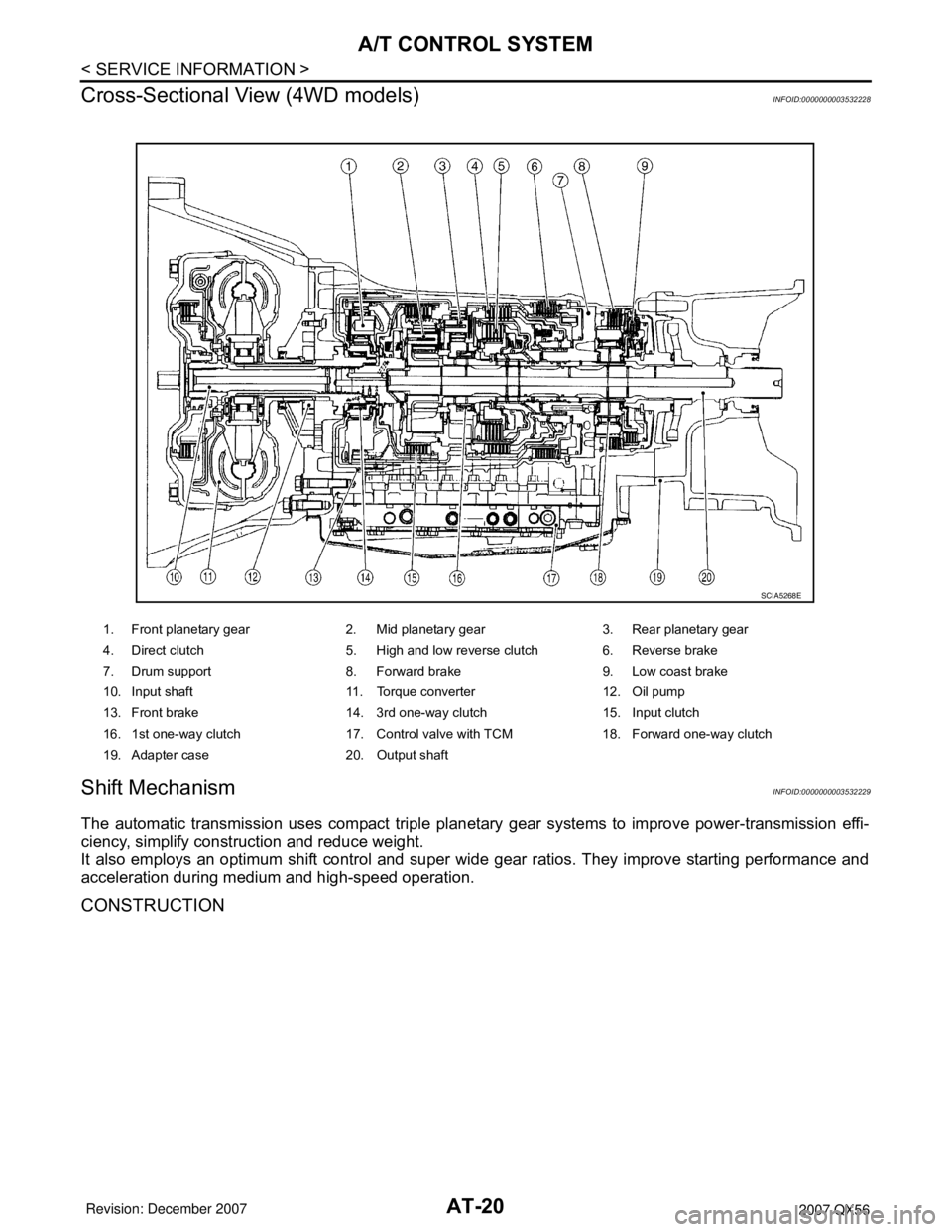
Cross-Sectional View (4WD models)
INFOID:0000000003532228
Shift MechanismINFOID:0000000003532229
The automatic transmission uses compact triple planetary gear systems to improve power-transmission effi-
ciency, simplify construction and reduce weight.
It also employs an optimum shift control and super wide gear ratios. They improve starting performance and
acceleration during medium and high-speed operation.
CONSTRUCTION
1. Front planetary gear 2. Mid planetary gear 3. Rear planetary gear
4. Direct clutch 5. High and low reverse clutch 6. Reverse brake
7. Drum support 8. Forward brake 9. Low coast brake
10. Input shaft 11. Torque converter 12. Oil pump
13. Front brake 14. 3rd one-way clutch 15. Input clutch
16. 1st one-way clutch 17. Control valve with TCM 18. Forward one-way clutch
19. Adapter case 20. Output shaft
SCIA5268E
Page 381 of 3061
PRECAUTIONSATC-11
< SERVICE INFORMATION >
C
DE
F
G H
I
K L
M A
B
AT C
N
O P
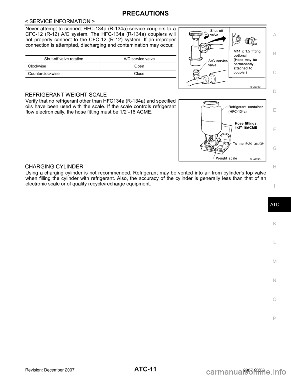
Never attempt to connect HFC-134a (R-134a) service couplers to a
CFC-12 (R-12) A/C system. T he HFC-134a (R-134a) couplers will
not properly connect to the CFC-12 (R-12) system. If an improper
connection is attempted, dischar ging and contamination may occur.
REFRIGERANT WEIGHT SCALE
Verify that no refrigerant other than HFC134a (R-134a) and specified
oils have been used with the scale. If the scale controls refrigerant
flow electronically, the hose fitting must be 1/2”-16 ACME.
CHARGING CYLINDER
Using a charging cylinder is not recommended. Refrigerant may be vented into air from cylinder's top valve
when filling the cylinder with refrigerant. Also, the accura cy of the cylinder is generally less than that of an
electronic scale or of quality recycle/recharge equipment.
Shut-off valve rotati on A/C service valve
Clockwise Open
Counterclockwise Close
RHA273D
RHA274D
Page 384 of 3061
ATC-14
< SERVICE INFORMATION >
PREPARATION
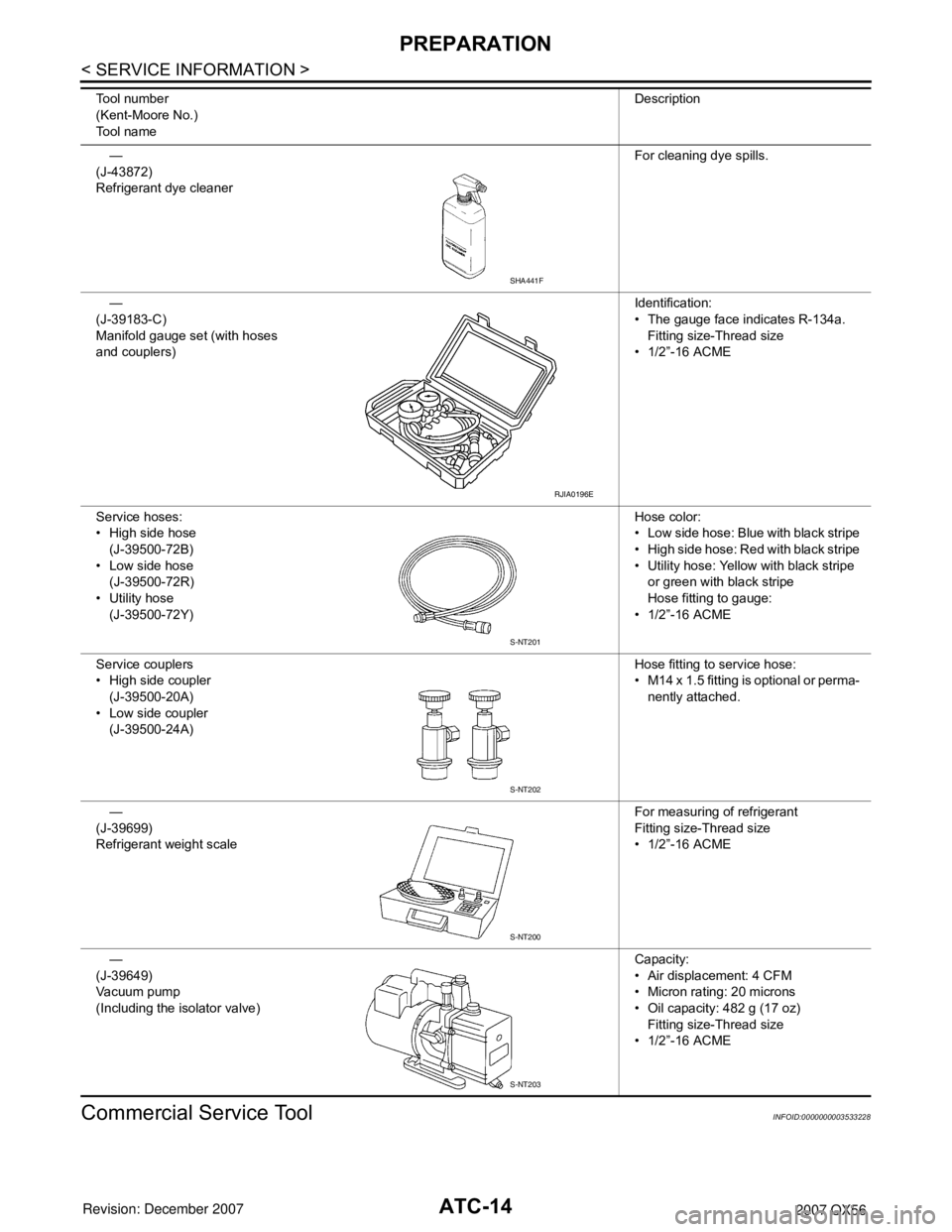
Commercial Service Tool
INFOID:0000000003533228
—
(J-43872)
Refrigerant dye cleaner For cleaning dye spills.
—
(J-39183-C)
Manifold gauge set (with hoses
and couplers) Identification:
• The gauge face indicates R-134a.
Fitting size-Thread size
• 1/2”-16 ACME
Service hoses:
• High side hose (J-39500-72B)
• Low side hose
(J-39500-72R)
• Utility hose (J-39500-72Y) Hose color:
• Low side hose: Blue with black stripe
• High side hose: Red with black stripe
• Utility hose: Yellow with black stripe
or green with black stripe
Hose fitting to gauge:
• 1/2”-16 ACME
Service couplers
• High side coupler (J-39500-20A)
• Low side coupler (J-39500-24A) Hose fitting to service hose:
• M14 x 1.5 fitting is optional or perma-
nently attached.
—
(J-39699)
Refrigerant weight scale For measuring of refrigerant
Fitting size-Thread size
• 1/2”-16 ACME
—
(J-39649)
Vacuum pump
(Including the isolator valve) Capacity:
• Air displacement: 4 CFM
• Micron rating: 20 microns
• Oil capacity: 482 g (17 oz)
Fitting size-Thread size
• 1/2”-16 ACME
Tool number
(Kent-Moore No.)
Tool name
Description
SHA441F
RJIA0196E
S-NT201
S-NT202
S-NT200
S-NT203
Page 520 of 3061

ATC-150
< SERVICE INFORMATION >
REFRIGERANT LINES
REFRIGERANT LINES
HFC-134a (R-134a) Service ProcedureINFOID:0000000003533291
SETTING OF SERVICE TOOLS AND EQUIPMENT
Discharging Refrigerant
WARNING:
Avoid breathing A/C refrigerant and oil vapor or mist. Exposure may irritate eyes, nose and throat.
Remove HFC-134a (R-134a) refrigerant from the A/C system using certified service equipment meeting
requirements of SAE J2210 HFC-134a (R-134a) r ecycling equipment or SAE J2201 HFC-134a (R-134a)
recovery equipment. If an accident al system discharge occurs, ventila te the work area before resum-
ing service. Additional h ealth and safety information may be obtain ed from the refrigerant and oil man-
ufacturers.
Evacuating System and Charging Refrigerant
1. Shut-off valve 2. A/C service valve 3. Recovery/recycling equipment
WJIA0579E
1. Shut-off valve 2. A/C service valve 3. Recovery/recycling equipment
4. Refrigerant container (HFC-134a) 5. Weight scale (J-39650) 6. Evacuating vacuum pump (J-39699)
7. Manifold gauge set (J-39183)
WJIA0580E
Page 723 of 3061
BL-12
< SERVICE INFORMATION >
HOOD
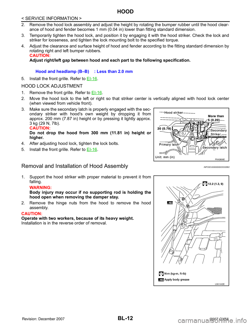
2. Remove the hood lock assembly and adjust the height by rotating the bumper rubber until the hood clear-
ance of hood and fender becomes 1 mm (0.04 in) lower than fitting standard dimension.
3. Temporarily tighten the hood lock, and position it by engaging it with the hood striker. Check the lock and
striker for looseness, and tighten the lock mounting bolt to the specified torque.
4. Adjust the clearance and surface height of hood and fender according to the fitting standard dimension by
rotating right and left bumper rubbers.
CAUTION:
Adjust right/left gap between hood and each part to the following specification.
5. Install the front grille. Refer to EI-16
.
HOOD LOCK ADJUSTMENT
1. Remove the front grille. Refer to EI-16.
2. Move the hood lock to the left or right so that striker center is vertically aligned with hood lock center
(when viewed from vehicle front).
3. Make sure the secondary latch is properly engaged with the sec-
ondary striker with hood's own weight by dropping it from
approx. 200 mm (7.87 in) height or by pressing it lightly approx.
3 kg (29 N, 7lb).
CAUTION:
Do not drop the hood from 300 mm (11.81 in) height or
higher.
4. After adjusting hood lock, tighten the lock bolts.
5. Install the front grille. Refer to EI-16
.
Removal and Installation of Hood AssemblyINFOID:0000000003532892
1. Support the hood striker with proper material to prevent it from
falling.
WARNING:
Body injury may occur if no supporting rod is holding the
hood open when removing the damper stay.
2. Remove the hinge nuts from the hood to remove the hood
assembly.
CAUTION:
Operate with two workers, because of its heavy weight.
Installation is in the reverse order of removal.Hood and headlamp (B–B) : Less than 2.0 mm
PIIA3806E
LIIA1443E
Page 725 of 3061
BL-14
< SERVICE INFORMATION >
HOOD
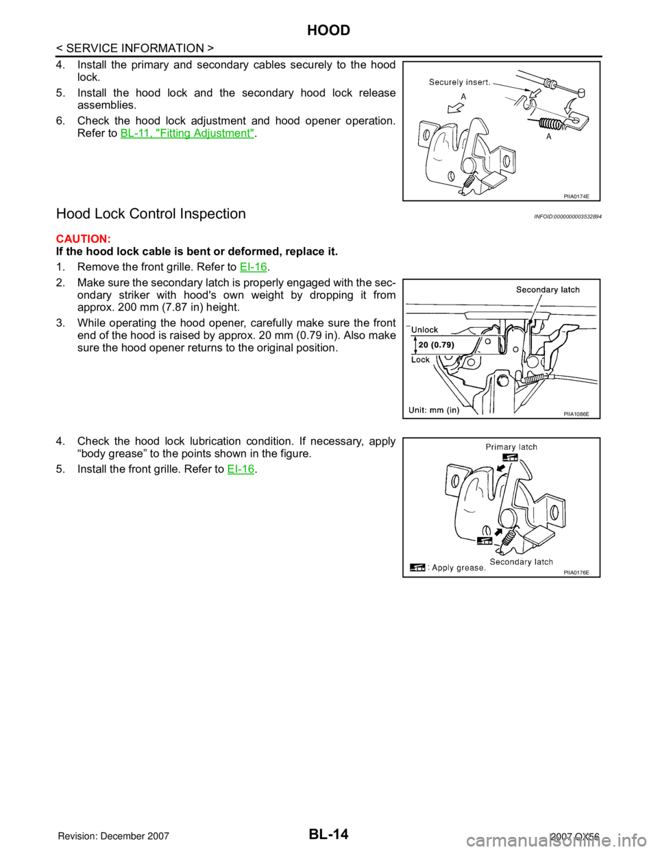
4. Install the primary and secondary cables securely to the hood
lock.
5. Install the hood lock and the secondary hood lock release
assemblies.
6. Check the hood lock adjustment and hood opener operation.
Refer to BL-11, "
Fitting Adjustment".
Hood Lock Control InspectionINFOID:0000000003532894
CAUTION:
If the hood lock cable is bent or deformed, replace it.
1. Remove the front grille. Refer to EI-16
.
2. Make sure the secondary latch is properly engaged with the sec-
ondary striker with hood's own weight by dropping it from
approx. 200 mm (7.87 in) height.
3. While operating the hood opener, carefully make sure the front
end of the hood is raised by approx. 20 mm (0.79 in). Also make
sure the hood opener returns to the original position.
4. Check the hood lock lubrication condition. If necessary, apply
“body grease” to the points shown in the figure.
5. Install the front grille. Refer to EI-16
.
PIIA0174E
PIIA1086E
PIIA0176E
Page 878 of 3061

BODY REPAIR
BL-167
< SERVICE INFORMATION >
C
D
E
F
G
H
J
K
L
MA
B
BL
N
O
P
Precaution in Repairing High Strength SteelINFOID:0000000003533012
High strength steel is used for body panels in order to reduce vehicle weight.
Accordingly, precautions in repairing automotive bodies made of high strength steel are described below:
High strength steel (hss) used in nissan vehicles
SP130 is the most commonly used HSS.
SP150 HSS is used only on parts that require much more strength.
Read the following precautions when repairing HSS:
1. Additional points to consider
• The repair of reinforcements (such as side members) by heat-
ing is not recommended since it may weaken the component.
When heating is unavoidable, do not heat HSS parts above
550°C (1,022°F).
Verify heating temperature with a thermometer.
(Crayon-type and other similar type thermometer are appropri-
ate.)
LIIA1061E
Tensile strength Nissan/Infiniti designation Major applicable parts
373 N/mm
2
(38kg/mm2 ,54klb/sq in)SP130• Front inner pillar upper
• Front pillar hinge brace
• Outer front pillar reinforcement
• Other reinforcements
785-981 N/mm
2
(80-100kg/mm2
114-142klb/sq in)SP150• Outer sill reinforcement
• Main back pillar
PIIA0115E
Page 1123 of 3061

EC-40
< SERVICE INFORMATION >
ON BOARD REFUELING VAPOR RECOVERY (ORVR)
ON BOARD REFUELING VAPOR RECOVERY (ORVR)
System DescriptionINFOID:0000000003531598
From the beginning of refueling, the air and vapor inside the fuel tank go through refueling EVAP vapor cut
valve and EVAP/ORVR line to the EVAP canister. The vapor is absorbed by the EVAP canister and the air is
released to the atmosphere.
When the refueling has reached the full level of the fuel tank, the refueling EVAP vapor cut valve is closed and
refueling is stopped because of auto shut-off. The vapor which was absorbed by the EVAP canister is purged
during driving.
WARNING:
When conducting inspections below, be sure to observe the following:
• Put a “CAUTION: FLAMMABLE” sign in workshop.
• Do not smoke while servicing fuel system. Keep open flames and sparks away from work area.
• Be sure to furnish the workshop with a CO
2 fire extinguisher.
CAUTION:
• Before removing fuel line parts, carry out the following procedures:
- Put drained fuel in an explosion-proof container and put lid on securely.
- Release fuel pressure from fuel line. Refer to EC-80, "
Fuel Pressure Check" .
- Disconnect battery ground cable.
• Always replace O-ring when the fuel gauge retainer is removed.
• Do not kink or twist hose and tube when they are installed.
• Do not tighten hose and clamps excessively to avoid damaging hoses.
• After installation, run engine and check for fuel leaks at connection.
• Do not attempt to top off the fuel tank after the fuel pump nozzle shuts off automatically.
Continued refueling may cause fuel overflow, resulting in fuel spray and possibly a fire.
Diagnosis ProcedureINFOID:0000000003531599
SYMPTOM: FUEL ODOR FROM EVAP CANISTER IS STRONG.
1.CHECK EVAP CANISTER
1. Remove EVAP canister with EVAP canister vent control valve and EVAP control system pressure sensor
attached.
2. Weigh the EVAP canister with EVAP canister vent control valve and EVAP control system pressure sensor
attached.
The weight should be less than 2.5 kg (5.5 lb).
OK or NG
OK >> GO TO 2.
NG >> GO TO 3.
2.CHECK IF EVAP CANISTER SATURATED WITH WATER
PBIB1068E