light INFINITI QX56 2008 Factory Service Manual
[x] Cancel search | Manufacturer: INFINITI, Model Year: 2008, Model line: QX56, Model: INFINITI QX56 2008Pages: 4083, PDF Size: 81.73 MB
Page 2159 of 4083

TERMINOLOGYGI-17
< HOW TO USE THIS MANUAL >
C
DE
F
G H
I
J
K L
M B
GI
N
O P
Exhaust gas recirculation control-BPT
valve EGRC-BPT valve
BPT valve
Exhaust gas recirculation control-solenoid
valve EGRC-solenoid valve
EGR control solenoid valve
Exhaust gas recirculation temperature sen-
sor EGRT sensorExhaust gas temperature sensor
EGR temperature sensor
Flash electrically erasable programmable
read only memory FEEPROM
***
Flash erasable programmable read only
memory FEPROM
***
Flexible fuel sensor FFS***
Flexible fuel system FF system***
Fuel pressure regulato r*** Pressure regulator
Fuel pressure regulator control solenoid
valve ***
PRVR control solenoid valve
Fuel trim FT***
Heated Oxygen sensor HO2S Exhaust gas sensor
Idle air control system IAC system Idle speed control
Idle air control valve-air regulato rIACV-air regulator Air regulator
Idle air control valve-auxiliary air control
valve IACV-AAC valve
Auxiliary air control (AAC) valve
Idle air control valve-FICD solenoid valve IACV-FICD solenoid valve FICD solenoid valve
Idle air control valve-idle up control sole-
noid valve IACV-idle up control solenoid valve Idle up control solenoid valve
Idle speed control-FI pot ISC-FI pot FI pot
Idle speed control system ISC system***
Ignition control IC***
Ignition control module ICM***
Indirect fuel injection system IFI system ***
Intake air IA Air
Intake air temperature sensor IAT sensor Air temperature sensor
Knock *** Detonation
Knock sensor KS Detonation sensor
Malfunction indicator lamp MIL Check engine light
Manifold absolute pressure MAP ***
Manifold absolute pressure sensor MAPS ***
Manifold differential pressure MDP ***
Manifold differential pressure sensor MDPS ***
Manifold su rface temperature MST ***
Manifold surface temperature sensor MSTS ***
Manifold vacuum zone MVZ ***
Manifold vacuum zone sensor MVZS***
Mass air flow sensor MAFS Air flow meter
Mixture control solenoid valve MC solenoid valveAir-fuel ratio control solenoid valve
Multiport fuel injection System MFI system Fuel injection control
NEW TERM
NEW ACRONYM /
ABBREVIATION OLD TERM
Revision: March 2010
2008 QX56
Page 2181 of 4083
SERVICE INFORMATION FOR ELECTRICAL INCIDENTGI-39
< BASIC INSPECTION >
C
DE
F
G H
I
J
K L
M B
GI
N
O P
lowing section illustrates ways to simulate the c onditions/environment under which the owner experiences an
electrical incident.
The section is broken into the six following topics:• Vehicle vibration
• Heat sensitive
• Freezing
• Water intrusion
• Electrical load
• Cold or hot start up
Get a thorough description of the incident from the customer . It is important for simulating the conditions of the
problem.
VEHICLE VIBRATION
The problem may occur or become worse while driving on a rough road or when engine is vibrating (idle with
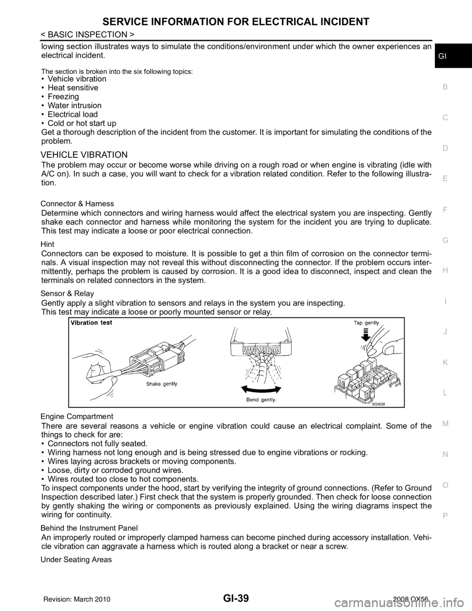
A/C on). In such a case, you will want to check for a vibration related condition. Refer to the following illustra-
tion.
Connector & Harness
Determine which connectors and wiring harness would affect the electrical system you are inspecting. Gently
shake each connector and harness while monitoring the syst em for the incident you are trying to duplicate.
This test may indicate a loose or poor electrical connection.
Hint
Connectors can be exposed to moisture. It is possible to get a thin film of corrosion on the connector termi-
nals. A visual inspection may not reveal this without disconnecting the connector. If the problem occurs inter-
mittently, perhaps the problem is caused by corrosi on. It is a good idea to disconnect, inspect and clean the
terminals on related connectors in the system.
Sensor & Relay
Gently apply a slight vibration to sensors and relays in the system you are inspecting.
This test may indicate a loose or poorly mounted sensor or relay.
Engine Compartment
There are several reasons a vehicle or engine vibration could cause an electrical complaint. Some of the
things to check for are:
• Connectors not fully seated.
• Wiring harness not long enough and is being stressed due to engine vibrations or rocking.
• Wires laying across brackets or moving components.
• Loose, dirty or corroded ground wires.
• Wires routed too close to hot components.
To inspect components under the hood, start by verifyi ng the integrity of ground connections. (Refer to Ground
Inspection described later.) First check that the system is properly grounded. Then check for loose connection
by gently shaking the wiring or components as previous ly explained. Using the wiring diagrams inspect the
wiring for continuity.
Behind the Instrument Panel
An improperly routed or improperly clamped harness can become pinched during accessory installation. Vehi-
cle vibration can aggravate a harness which is routed along a bracket or near a screw.
Under Seating Areas
SGI839
Revision: March 2010 2008 QX56
Page 2185 of 4083
SERVICE INFORMATION FOR ELECTRICAL INCIDENTGI-43
< BASIC INSPECTION >
C
DE
F
G H
I
J
K L
M B
GI
N
O P
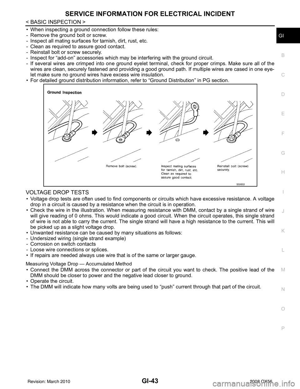
• When inspecting a ground connection follow these rules:
- Remove the ground bolt or screw.
- Inspect all mating surfaces for tarnish, dirt, rust, etc.
- Clean as required to assure good contact.
- Reinstall bolt or screw securely.
- Inspect for “add-on” accessories which may be interfering with the ground circuit.
- If several wires are crimped into one ground eyelet terminal, check for proper crimps. Make sure all of the wires are clean, securely fastened and providing a good ground path. If multiple wires are cased in one eye-
let make sure no ground wires have excess wire insulation.
• For detailed ground distribution information, refer to “Ground Distribution” in PG section.
VOLTAGE DROP TESTS
• Voltage drop tests are often used to find components or circuits which have excessive resistance. A voltage drop in a circuit is caused by a resistance when the circuit is in operation.
• Check the wire in the illustration. When measuring re sistance with DMM, contact by a single strand of wire
will give reading of 0 ohms. This would indicate a good circuit. When the circuit operates, this single strand
of wire is not able to carry the current. The single strand will have a high resistance to the current. This will
be picked up as a slight voltage drop.
• Unwanted resistance can be caused by many situations as follows:
- Undersized wiring (single strand example)
- Corrosion on switch contacts
- Loose wire connections or splices.
• If repairs are needed always use wire that is of the same or larger gauge.
Measuring Voltage Drop — Accumulated Method
• Connect the DMM across the connector or part of the ci rcuit you want to check. The positive lead of the
DMM should be closer to power and the negative lead closer to ground.
• Operate the circuit.
• The DMM will indicate how many volts are being used to “push” current through that part of the circuit.
SGI853
Revision: March 2010 2008 QX56
Page 2186 of 4083
GI-44
< BASIC INSPECTION >
SERVICE INFORMATION FOR ELECTRICAL INCIDENT
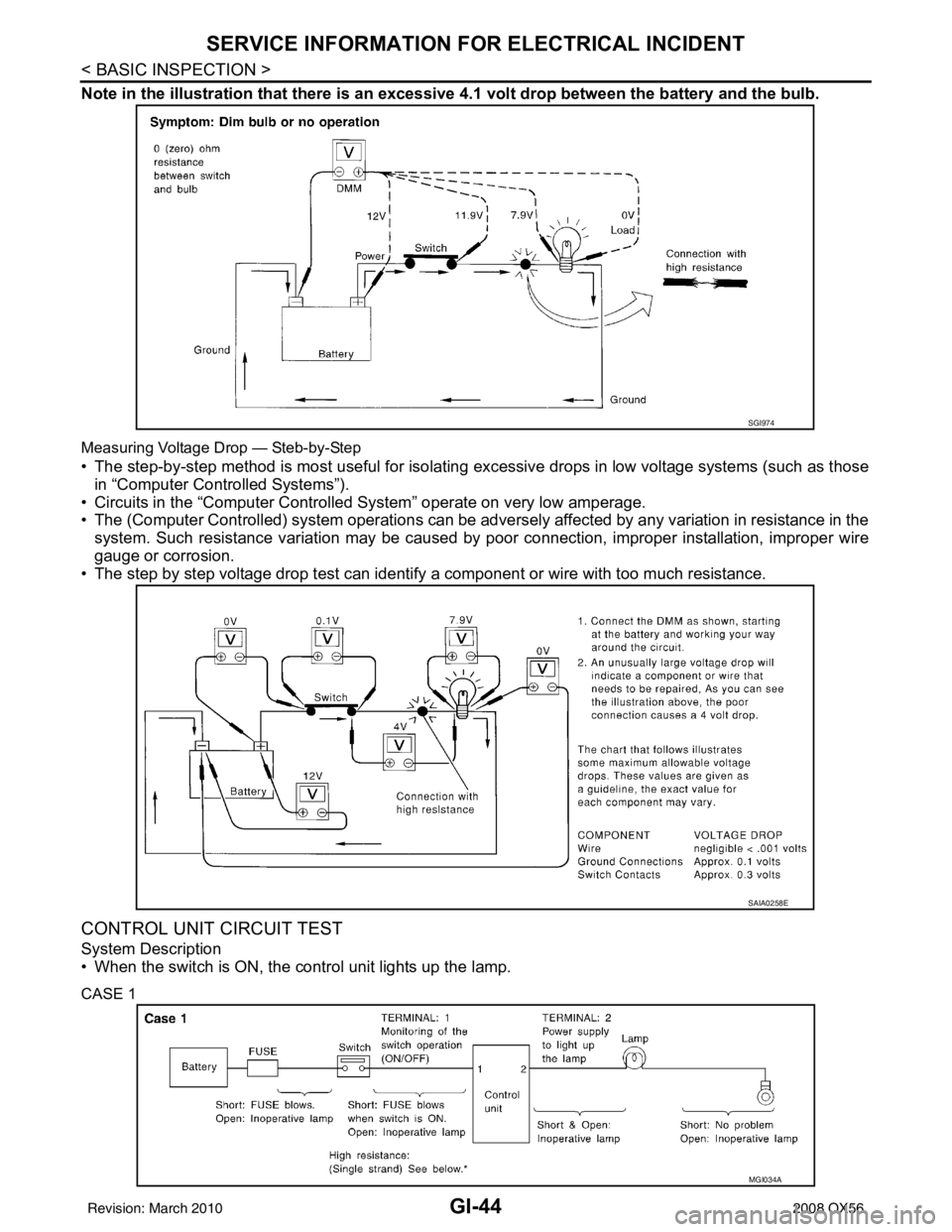
Note in the illustration that there is an excessive 4.1 volt drop between the battery and the bulb.
Measuring Voltage Drop — Steb-by-Step
• The step-by-step method is most useful for isolating excessive drops in low voltage systems (such as those
in “Computer Controlled Systems”).
• Circuits in the “Computer Controlled System” operate on very low amperage.
• The (Computer Controlled) system oper ations can be adversely affected by any variation in resistance in the
system. Such resistance variation may be caused by poor connection, improper installation, improper wire
gauge or corrosion.
• The step by step voltage drop test can identify a component or wire with too much resistance.
CONTROL UNIT CIRCUIT TEST
System Description
• When the switch is ON, the control unit lights up the lamp.
CASE 1
SGI974
SAIA0258E
MGI034A
Revision: March 2010 2008 QX56
Page 2200 of 4083
GW-10
< ON-VEHICLE REPAIR >
FRONT DOOR GLASS AND REGULATOR
NOTE:
If any of the following work has been done, reset the power window motor limit switch.
• Removal and installation of the regulator assembly.
• Removal and installation of the power window motor from the regulator.
• Installation of a new glass window.
• Installation of a new glass run.
Check the label on the power window motor for the part number. If the power window motor part number
matches one of the following, the motor must be removed from the regulator and the limit switch reset using
the "INSTALLATION WITHOUT RESET SWITCH" pr ocedure in "FRONT DOOR GLASS REGULATOR
ASSEMBLY".
• 80730-ZT01A
• 80731-ZT01A
• 80730-ZM70B
• 80731-ZM70B
If the power window motor part number does not match one of the part numbers above, the limit switch can be
reset in the vehicle using the "INSTA LLATION WITH RESET SWITCH" procedure.
NOTE:
• The label can be checked with the power window motor in the vehicle by using a mirror.
• Some of the power window motors with the part num bers above may appear to have a reset switch, but it will
not reset the limit switch.
Fitting Inspection
• Check that the glass is securely fit into the glass run groove.
• Lower the glass slightly [approximately 10 to 20 mm (0 .39 to 0.79 in)] and check that the clearance to the
sash is parallel. If the clearance between the glass and sash is not parallel, loosen the regulator bolts, guide
rail bolts, and glass and guide rail bolts to correct the glass position.
FRONT DOOR GLASS REGULATOR ASSEMBLY
Removal
1. Remove the front door finisher panel. Refer to INT-11, "Removal and Installation".
2. Position aside the vapor barrier.
3. Remove the hole cover over rear glass bolt.
4. Operate the power window main switch to raise/ lower the door window until the glass bolts can be seen.
5. Remove the inside seal.
6. Remove the glass bolts.
7. Raise the front door glass and hold it in place with suitable tool.
8. Disconnect the harness connector fr om the regulator assembly.
9. Remove the bolts and the regulator assembly.
Disassembly And Assembly
Remove the regulator motor from the regulator assembly.
Inspection After Removal
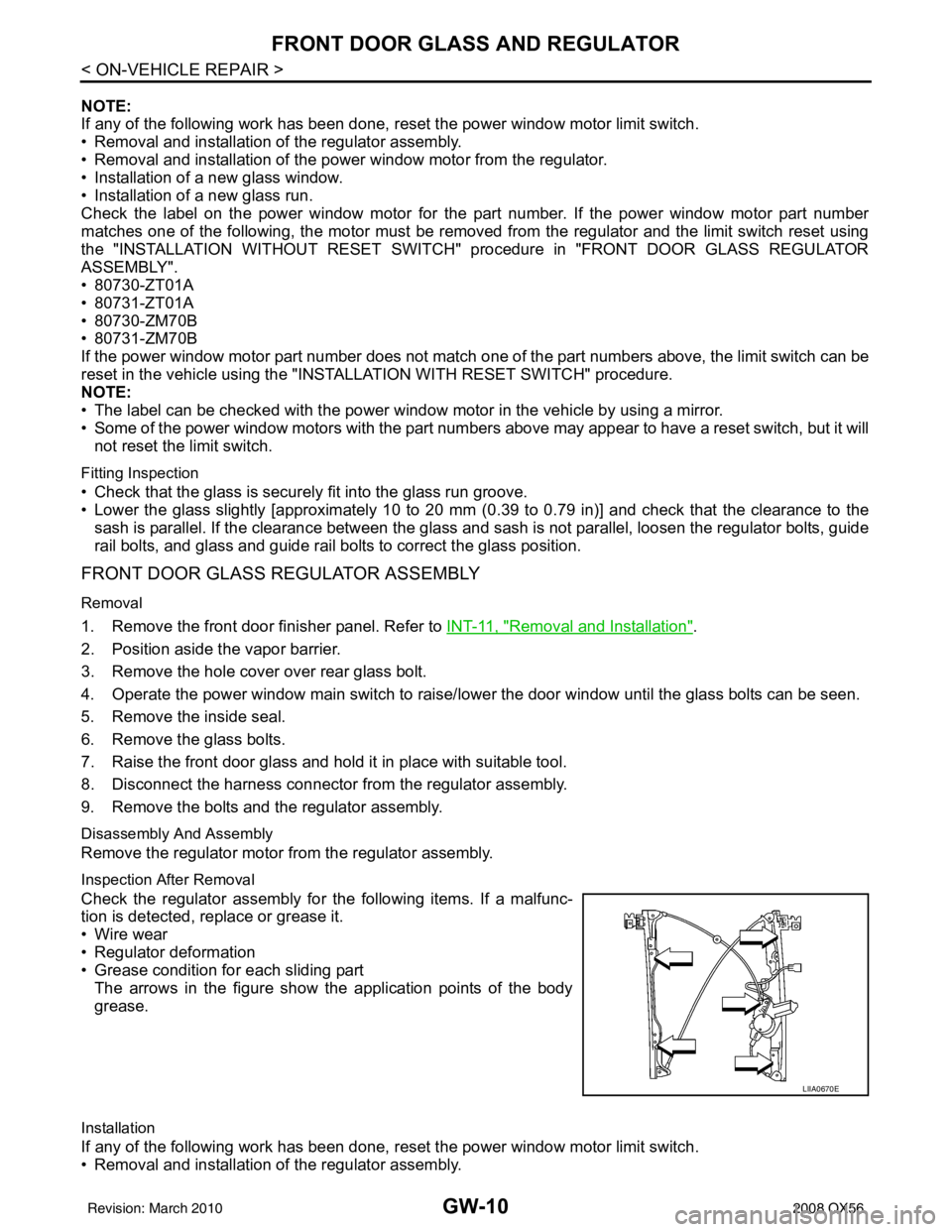
Check the regulator assembly for the following items. If a malfunc-
tion is detected, replace or grease it.
• Wire wear
• Regulator deformation
• Grease condition for each sliding part The arrows in the figure show the application points of the body
grease.
Installation
If any of the following work has been done, reset the power window motor limit switch.
• Removal and installation of the regulator assembly.
LIIA0670E
Revision: March 2010 2008 QX56
Page 2203 of 4083
REAR DOOR GLASS AND REGULATORGW-13
< ON-VEHICLE REPAIR >
C
DE
F
G H
I
J
L
M A
B
GW
N
O P
REAR DOOR GLASS AND REGULATOR
Removal and InstallationINFOID:0000000001608356
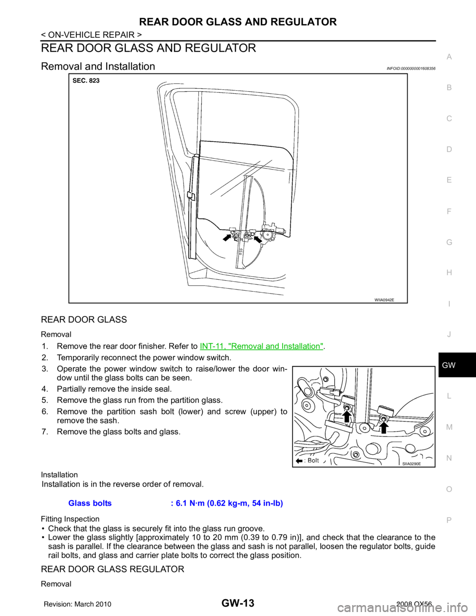
REAR DOOR GLASS
Removal
1. Remove the rear door finisher. Refer to INT-11, "Removal and Installation".
2. Temporarily reconnect the power window switch.
3. Operate the power window switch to raise/lower the door win- dow until the glass bolts can be seen.
4. Partially remove the inside seal.
5. Remove the glass run from the partition glass.
6. Remove the partition sash bolt (lower) and screw (upper) to remove the sash.
7. Remove the glass bolts and glass.
Installation
Installation is in the reverse order of removal.
Fitting Inspection
• Check that the glass is securely fit into the glass run groove.
• Lower the glass slightly [approximately 10 to 20 mm (0 .39 to 0.79 in)], and check that the clearance to the
sash is parallel. If the clearance between the glass and sash is not parallel, loosen the regulator bolts, guide
rail bolts, and glass and carrier plate bolts to correct the glass position.
REAR DOOR GLASS REGULATOR
Removal
WIIA0942E
SIIA0290E
Glass bolts : 6.1 N·m (0.62 kg-m, 54 in-lb)
Revision: March 2010 2008 QX56
Page 2219 of 4083
HA-14
< PREPARATION >
PREPARATION
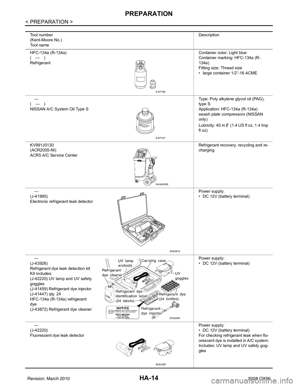
Tool number
(Kent-Moore No.)
Tool nameDescription
HFC-134a (R-134a)
(—)
Refrigerant Container color: Light blue
Container marking: HFC-134a (R-
134a)
Fitting size: Thread size
• large container 1/2”-16 ACME
—
(—)
NISSAN A/C System Oil Type S Type: Poly alkylene glycol oil (PAG),
type S
Application: HFC-134a (R-134a)
swash plate compressors (NISSAN
only)
Lubricity: 40 m (1.4 US fl oz, 1.4 Imp
fl oz)
KV991J0130
(ACR2005-NI)
ACR5 A/C Service Center Refrigerant recovery, recycling and re-
charging
—
(J-41995)
Electronic refrigerant leak detector Power supply:
• DC 12V (battery terminal)
—
(J-43926)
Refrigerant dye leak detection kit
Kit includes:
(J-42220) UV lamp and UV safety
goggles
(J-41459) Refrigerant dye injector
(J-41447) qty. 24
HFC-134a (R-134a) refrigerant
dye
(J-43872) Refrigerant dye cleaner Power supply:
• DC 12V (battery terminal)
—
(J-42220)
Fluorescent dye leak detector Power supply:
• DC 12V (battery terminal)
For checking refrigerant leak when flu-
orescent dye is installed in A/C system.
Includes: UV lamp and UV safety gog-
gles
S-NT196
S-NT197
WJIA0293E
AHA281A
ZHA200H
SHA438F
Revision: March 2010
2008 QX56
Page 2229 of 4083

HA-24
< ON-VEHICLE MAINTENANCE >
FLUORESCENT LEAK DETECTOR
FLUORESCENT LEAK DETECTOR
Checking of Refrigerant LeaksINFOID:0000000001516646
PRELIMINARY CHECK
Perform a visual inspection of all refrigeration parts, fittings, hoses and components for signs of A/C oil leak-
age, damage, and corrosion. Any A/C oil leakage may indicate an area of refrigerant leakage. Allow extra
inspection time in these areas when using either an el ectronic refrigerant leak detector (J-41995) or fluores-
cent dye leak detector (J-42220).
If any dye is observed using a fluorescent dye leak detector (J-42220), confirm the leak using a electronic
refrigerant leak detector (J-41995). It is possible that the dye is from a prior leak that was repaired and not
properly cleaned.
When searching for leaks, do not stop when one leak is found but continue to check for additional leaks at all
system components and connections.
When searching for refrigerant leaks using an electronic refrigerant leak detector (J-41995), move the probe
along the suspected leak area at 25 - 50 mm (1 - 2 in) per second and no further than 6 mm (1/4 in) from the
component.
CAUTION:
Moving the electronic refrigerant l eak detector probe slower and closer to the suspected leak area will
improve the chances of finding a leak.
Checking System for L eaks Using the Fluorescent Dye Leak DetectorINFOID:0000000001516647
1. Check the A/C system for leaks using the fluorescent dye leak detector and safety goggles (J-42220) in a
low sunlight area (area without windows preferable). Il luminate all components, fittings and lines. The dye
will appear as a bright green/yellow area at the point of leakage. Fluorescent dye observed at the evapo-
rator drain opening indicates an evaporator core asse mbly leak (tubes, core or expansion valve).
2. If the suspected area is difficult to see, use an adjustable mirror or wipe the area with a clean shop rag or cloth, then inspect the shop rag or cloth with the fl uorescent dye leak detector (J-42220) for dye residue.
3. After the leak is repaired, remove any residual dye using refrigerant dye cleaner (J-43872) to prevent
future misdiagnosis.
4. Perform a system performance check and then verify t he leak repair using a electronic refrigerant leak
detector (J-41995).
NOTE:
• Other gases in the work area or substances on the A/C components, for example, anti-freeze, wind-
shield washer fluid, solvents and oils, may falsely tri gger the leak detector. Make sure the surfaces to be
checked are clean.
• Clean with a dry cloth or blow off with shop air.
• Do not allow the sensor tip of the electronic refri gerant leak detector (J-41995) to contact with any sub-
stance. This can also cause false readings and may damage the detector.
Dye InjectionINFOID:0000000001516648
NOTE:
This procedure is only necessary when recharging the system or when the compressor has seized and must
be replaced.
1. Check the A/C system static (at rest) pressure . Pressure must be at least 345 kPa (3.52 kg/cm
2 , 50 psi).
2. Pour one bottle 7.4 cc (1/4 ounce) of the HFC-134a (R -134a) fluorescent leak detection dye (J-41447) into
the HFC-134a (R-134a) dye injector (J-41459).
CAUTION:
If repairing the A/C system or replacing a co mponent, pour the HFC-134a (R-134a) fluorescent leak
detection dye (J-41447) directly into the open system connection and proceed with the service
procedures.
3. Connect the refrigerant dye injector (J-41459) to the low-pressure service valve.
4. Start the engine and switch the A/C system ON.
5. When the A/C system is operating (compressor running), inject one bottle 7.4 cc (1/4 ounce) of HFC-134a (R-134a) fluorescent leak detection dye (J-41447) through the low-pressure service valve using HFC-
134a (R-134a) dye injector (J-41459). Refer to the manufacturer's operating instructions.
Revision: March 2010 2008 QX56
Page 2257 of 4083
![INFINITI QX56 2008 Factory Service Manual HAC-4
< BASIC INSPECTION >[AUTOMATIC AIR CONDITIONER]
INSPECTION AND ADJUSTMENT
INSPECTION AND ADJUSTMENT
Operational Check (Front)INFOID:0000000001679764
The purpose of the operational check is to
c INFINITI QX56 2008 Factory Service Manual HAC-4
< BASIC INSPECTION >[AUTOMATIC AIR CONDITIONER]
INSPECTION AND ADJUSTMENT
INSPECTION AND ADJUSTMENT
Operational Check (Front)INFOID:0000000001679764
The purpose of the operational check is to
c](/img/42/57030/w960_57030-2256.png)
HAC-4
< BASIC INSPECTION >[AUTOMATIC AIR CONDITIONER]
INSPECTION AND ADJUSTMENT
INSPECTION AND ADJUSTMENT
Operational Check (Front)INFOID:0000000001679764
The purpose of the operational check is to
confirm that the system operates properly.
CHECKING MEMORY FUNCTION
1. Set the temperature to 32 °C (90 °F).
2. Press the OFF switch.
3. Turn ignition switch OFF.
4. Turn ignition switch ON.
5. Press the AUTO switch.
6. Confirm that the set temperature remains at previous temperature.
7. Press the OFF switch.
If NG, go to trouble diagnosis procedure for HAC-121, "
Memory Function Check".
If OK, continue with next check.
CHECKING BLOWER
1. Press the blower speed control switch (+) once, blower should operate on low speed. The fan display should have one bar lit (on display).
2. Press the blower speed control switch (+) again, and continue checking blower speed and fan display until
all speeds are checked.
3. Leave blower on maximum speed.
If NG, go to trouble diagnosis procedure for HAC-51, "
Front Blower Motor Diagnosis Procedure".
If OK, continue with next check.
CHECKING DISCHARGE AIR
1. Press MODE switch four times and the DEF switch.
2. Each position indicator should change shape (on display).
3. Confirm that discharge air comes out according to the air distribution table. Refer to HAC-15, "
Discharge
Air Flow (Front)".
Mode door position is checked in the next step.
If NG, go to trouble diagnosis procedure for HAC-26, "
Mode Door Motor (Front) Diagnosis Procedure".
If OK, continue the check.
NOTE:
Confirm that the compressor clutch is engaged (sound or visual inspection) and intake door position is at
fresh when the DEF or D/F is selected.
CHECKING RECIRCULATION ( , ONLY)
1. Press recirculation ( ) switch one time. Recirculation indicator should illuminate.
2. Press recirculation ( ) switch one more time. Recirculation indicator should go off.
3. Listen for intake door position change (blower sound should change slightly).
If NG, go to trouble diagnosis procedure for HAC-42, "
Intake Door Motor Diagnosis Procedure".
If OK, continue the check.
NOTE:
Confirm that the compressor clutch is engaged (sound or vis ual inspection) and intake door position is at fresh
when the DEF or D/F is selected. REC ( ) is not allowed in DEF ( ) D/F ( ) or FOOT ( ).
CHECKING TEMPERATURE DECREASE
1. Rotate temperature control dial (drive or passenger) counterclockwise until 18° C (60°F) is displayed.
2. Check for cold air at appropriate discharge air outlets. Conditions : Engine running and at normal operating temperature
Revision: March 2010
2008 QX56
Page 2294 of 4083
![INFINITI QX56 2008 Factory Service Manual INTAKE DOOR MOTORHAC-41
< COMPONENT DIAGNOSIS > [AUTOMATIC AIR CONDITIONER]
C
D
E
F
G H
J
K L
M A
B
HAC
N
O P
COMPONENT DESCRIPTION
Intake door motor
The intake door motor is attached to the intake un INFINITI QX56 2008 Factory Service Manual INTAKE DOOR MOTORHAC-41
< COMPONENT DIAGNOSIS > [AUTOMATIC AIR CONDITIONER]
C
D
E
F
G H
J
K L
M A
B
HAC
N
O P
COMPONENT DESCRIPTION
Intake door motor
The intake door motor is attached to the intake un](/img/42/57030/w960_57030-2293.png)
INTAKE DOOR MOTORHAC-41
< COMPONENT DIAGNOSIS > [AUTOMATIC AIR CONDITIONER]
C
D
E
F
G H
J
K L
M A
B
HAC
N
O P
COMPONENT DESCRIPTION
Intake door motor
The intake door motor is attached to the intake unit. It rotates so that
air is drawn from inlets set by the A/C auto amp. Motor rotation is
conveyed to a lever which activates the intake door.
Intake Door Motor Component Function CheckINFOID:0000000001679790
INSPECTION FLOW
1.CONFIRM SYMPTOM BY PERFORMING OPERATIONAL CHECK - REC ( )
1. Press the mode switch to vent mode( ).
2. Press REC ( ) switch. The REC ( )indicator should illuminate.
3. Press REC ( ) switch again. The REC ( ) indicator should go out.
4. Listen for intake door position change (you should hear blower sound change slightly).
Can a symptom be duplicated?
YES >> GO TO 3.
NO >> GO TO 2.
2.PERFORM COMPLETE OPERATIONAL CHECK
Perform a complete operational check and check for any symptoms. Refer to HAC-4, "
Operational Check
(Front)".
Can a symptom be duplicated?
YES >> Refer to HAC-3, "How to Perform Trouble Diagnosis For Quick And Accurate Repair".
NO >> System OK.
3.CHECK FOR SERVICE BULLETINS
Check for any service bulletins.
>> GO TO 4.
4.CHECK INTAKE DOOR OPERATION
Check and verify intake door me chanism for smooth operation.
Is the inspection result normal?
YES >> GO TO 5.
NO >> Repair intake door mechanism.
5.PERFORM SELF-DIAGNOSIS
Perform self-diagnosis to check for any codes. Refer to HAC-22, "
A/C and AV Switch Assembly Self-Diagno-
sis".
Are any self-diagnosis codes present?
YES >> Refer to HAC-23, "A/C System Self-Diagnosis Code Chart".
NO >> GO TO 6.
6.RECHECK FOR ANY SYMPTOMS
Perform a complete operational check for any symptoms. Refer to HAC-4, "
Operational Check (Front)".
Does another symptom exist?
YES >> Refer to HAC-3, "How to Perform Trouble Diagnosis For Quick And Accurate Repair".
NO >> Replace A/C auto amp. Refer to VTL-7, "
Removal and Installation".
WJIA0552E
Revision: March 2010 2008 QX56