INFINITI QX56 2008 Factory Service Manual
QX56 2008
INFINITI
INFINITI
https://www.carmanualsonline.info/img/42/57030/w960_57030-0.png
INFINITI QX56 2008 Factory Service Manual
Page 1953 of 4083

DIAGNOSIS SYSTEM (BCM)EXL-25
< FUNCTION DIAGNOSIS >
C
DE
F
G H
I
J
K
M A
B
EXL
N
O P
1: The item is indicated, not monitored.
FLASHER
FLASHER : CONSULT-III Function (BCM - FLASHER)INFOID:0000000001547121
DATA MONITOR
ACTIVE TEST
FR FOG LAMP ON
Transmits the front fog lamp light request signal to IPDM E/R via CAN
communication to turn the front fog lamp ON.
OFF Stops the front fog lamp request signal transmission.
CORNERING LAMP
1
RH —
LH
OFF
CARGO LAMP ON
Tramsmits the cargo lamp request signal to the IPDM E/R via CAN com-
munication to turn on the cargo lamp.
OFF Stops the cargo lamp request signal transmission.
Test item
Operation Description
Monitor item
[Unit] Description
IGN ON SW
[ON/OFF] The switch status input from the ignition switch
HAZARD SW
[ON/OFF] The switch status input from the hazard warning switch
TURN SIGNAL R
[ON/OFF] Each switch condition that BCM judges from the combination switch reading function
TURN SIGNAL L
[ON/OFF]
BRAKE SW
[ON/OFF] The switch status input from the brake switch
Test item
Operation Description
FLASHER RH Blinks right turn signal lamp.
LH Blinks left turn signal lamp.
OFF Turns turn signal lamps (right and left) OFF.
Revision: March 2010 2008 QX56
Page 1954 of 4083

EXL-26
< FUNCTION DIAGNOSIS >
DIAGNOSIS SYSTEM (IPDM E/R)
DIAGNOSIS SYSTEM (IPDM E/R)
CONSULT - III Function (IPDM E/R)INFOID:0000000001547122
APPLICATION ITEM
CONSULT-III performs the following functi ons via CAN communication with IPDM E/R.
DATA MONITOR
Monitor item
ACTIVE TEST
Te s t i t e m
Diagnosis mode Description
Self Diagnostic Result Displays the diagnosis results judged by IPDM E/R.
Data Monitor Displays the real-time input/output data from IPDM E/R input/output data.
Active Test IPDM E/R can provide a drive signal to electronic components to check their operations.
CAN Diag Support Monitor The results of transmit/receive diagnosis of CAN communication can be read.
Monitor Item
[Unit] MAIN SIG-
NALS Description
TAIL & CLR REQ
[Off/On] ×Displays the status of the tail and clearance lamp request signal received from
BCM via CAN communication.
HL LO REQ
[Off/On] ×
Displays the status of the low beam request signal received from BCM via CAN
communication.
HL HI REQ
[Off/On] ×
Displays the status of the high beam request signal received from BCM via CAN
communication.
FR FOG REQ
[Off/On] ×Displays the status of the front fog light request signal received from BCM via
CAN communication.
IGN RLY
[Off/On] ×
Displays the status of the ignition relay judged by the IPDM E/R-.
DTRL REQ
[Off] ×
Displays the status of the daytime light request signal received from the BCM via
CAN communication.
Test item
Operation Description
EXTERNAL LAMPS Off
OFF
TAIL Operates the tail lamp relay.
Lo Operates the headlamp low relay.
Hi Operates the headlamp low relay and ON/OFF the headlamp high relay at 1 sec-
ond intervals.
Fog Operates the front fog lamp relay.
Revision: March 2010 2008 QX56
Page 1968 of 4083

EXL-40
< COMPONENT DIAGNOSIS >
OPTICAL SENSOR
OPTICAL SENSOR
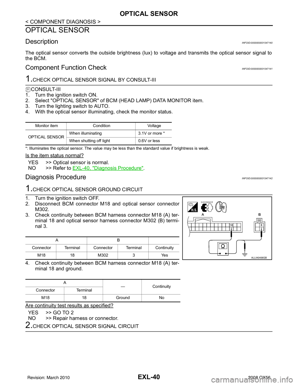
DescriptionINFOID:0000000001547140
The optical sensor converts the outside brightness (lux) to voltage and transmits the optical sensor signal to
the BCM.
Component Function CheckINFOID:0000000001547141
1.CHECK OPTICAL SENSOR SIGNAL BY CONSULT-III
CONSULT-III
1. Turn the ignition switch ON.
2. Select "OPTICAL SENSOR" of BCM (HEAD LAMP) DATA MONITOR item.
3. Turn the lighting switch to AUTO.
4. With the optical sensor illuminating, check the monitor status.
*: Illuminates the optical sensor. The value may be less than the standard value if brightness is weak.
Is the item status normal?
YES >> Optical sensor is normal.
NO >> Refer to EXL-40, "
Diagnosis Procedure".
Diagnosis ProcedureINFOID:0000000001547142
1.CHECK OPTICAL SENSOR GROUND CIRCUIT
1. Turn the ignition switch OFF.
2. Disconnect BCM connector M18 and optical sensor connector M302.
3. Check continuity between BCM harness connector M18 (A) ter-
minal 18 and optical sensor harness connector M302 (B) termi-
nal 3.
4. Check continuity between BCM harness connector M18 (A) ter- minal 18 and ground.
Are continuity test results as specified?
YES >> GO TO 2
NO >> Repair harness or connector.
2.CHECK OPTICAL SENSOR SIGNAL CIRCUIT
Monitor item ConditionVoltage
OPTICAL SENSOR When illuminating
3.1V or more *
When shutting off light 0.6V or less
AB
Connector Terminal Connector Terminal Continuity M18 18M302 3Yes
A —Continuity
Connector Terminal
M18 18Ground No
ALLIA0406GB
Revision: March 2010 2008 QX56
Page 1975 of 4083
DAYTIME LIGHT SYSTEMEXL-47
< COMPONENT DIAGNOSIS >
C
DE
F
G H
I
J
K
M A
B
EXL
N
O P
DAYTIME LIGHT SYSTEM
Wiring DiagramINFOID:0000000001547144
AWLWA0024GB
Revision: March 2010 2008 QX56
Page 1976 of 4083
EXL-48
< COMPONENT DIAGNOSIS >
DAYTIME LIGHT SYSTEM
AWLWA0025GB
Revision: March 20102008 QX56
Page 1977 of 4083
DAYTIME LIGHT SYSTEMEXL-49
< COMPONENT DIAGNOSIS >
C
DE
F
G H
I
J
K
M A
B
EXL
N
O P
ALLIA0505GB
Revision: March 2010 2008 QX56
Page 1978 of 4083
EXL-50
< COMPONENT DIAGNOSIS >
DAYTIME LIGHT SYSTEM
AALIA0184GB
Revision: March 20102008 QX56
Page 1979 of 4083
DAYTIME LIGHT SYSTEMEXL-51
< COMPONENT DIAGNOSIS >
C
DE
F
G H
I
J
K
M A
B
EXL
N
O P
AWLIA0156GB
Revision: March 2010 2008 QX56
Page 1980 of 4083
EXL-52
< COMPONENT DIAGNOSIS >
DAYTIME LIGHT SYSTEM
AWLIA0157GB
Revision: March 20102008 QX56
Page 1981 of 4083
DAYTIME LIGHT SYSTEMEXL-53
< COMPONENT DIAGNOSIS >
C
DE
F
G H
I
J
K
M A
B
EXL
N
O P
ALLIA0509GB
Revision: March 2010 2008 QX56


