light INFINITI QX56 2008 Factory Service Manual
[x] Cancel search | Manufacturer: INFINITI, Model Year: 2008, Model line: QX56, Model: INFINITI QX56 2008Pages: 4083, PDF Size: 81.73 MB
Page 2298 of 4083
![INFINITI QX56 2008 Factory Service Manual DEFROSTER DOOR MOTOR CIRCUITHAC-45
< COMPONENT DIAGNOSIS > [AUTOMATIC AIR CONDITIONER]
C
D
E
F
G H
J
K L
M A
B
HAC
N
O P
Defroster Door Motor Co mponent Function CheckINFOID:0000000001679793
INSPECTIO INFINITI QX56 2008 Factory Service Manual DEFROSTER DOOR MOTOR CIRCUITHAC-45
< COMPONENT DIAGNOSIS > [AUTOMATIC AIR CONDITIONER]
C
D
E
F
G H
J
K L
M A
B
HAC
N
O P
Defroster Door Motor Co mponent Function CheckINFOID:0000000001679793
INSPECTIO](/img/42/57030/w960_57030-2297.png)
DEFROSTER DOOR MOTOR CIRCUITHAC-45
< COMPONENT DIAGNOSIS > [AUTOMATIC AIR CONDITIONER]
C
D
E
F
G H
J
K L
M A
B
HAC
N
O P
Defroster Door Motor Co mponent Function CheckINFOID:0000000001679793
INSPECTION FLOW
1.CONFIRM SYMPTOM BY PERFORMING O PERATIONAL CHECK - DEFROSTER DOOR
1. Press the mode switch and select vent ( ).
2. Press the defrost switch ( ). Defroster indicator should illuminate (on display).
3. Listen for defroster door position change (blower sound should change slightly).
Can the symptom be duplicated?
YES >> GO TO 3.
NO >> GO TO 2.
2.CHECK FOR ANY SYMPTOMS
Perform a complete operational check for any symptoms. Refer to HAC-4, "
Operational Check (Front)".
Does another symptom exist?
YES >> Refer to HAC-3, "How to Perform Trouble Diagnosis For Quick And Accurate Repair".
NO >> SYSTEM OK.
3.CHECK FOR SERVICE BULLETINS
Check for any service bulletins.
>> GO TO 4.
4.CHECK DEFROSTER DOOR MOTOR
Perform diagnostic procedure for defroster door motor. Refer to HAC-45, "
Defroster Door Motor Component
Function Check".
Is the inspection result normal?
YES >> GO TO 5.
NO >> Repair PBR circuit or replace defroster door motor. Refer to VTL-21, "
Removal and Installation".
5.CHECK DEFROSTER DOOR OPERATION
Check and verify defroster door mechanism for smooth operation.
Is the inspection result normal?
YES >> Replace defroster door motor. Refer to VTL-21, "Removal and Installation".
NO >> Repair defroster door mechanism.
Defroster Door Motor Diagnosis ProcedureINFOID:0000000001679794
SYMPTOM:
• Defroster door does not change.
• Defroster door motor does not operate normally.
DIAGNOSTIC PROCEDURE FOR DEFROSTER DOOR MOTOR
1.CHECK A/C AUTO AMP. FOR POWER AND GROUND
1. Turn ignition switch ON.
2. Press the defroster switch ( ).
3. Check voltage between A/C auto amp. harness connector M49 terminal 24 and terminal 23 and press the defroster switch ( )
again.
Connector Te r m i n a l s
Condition Voltage
(Approx.)
(+) (-)
A/C auto amp.: M49 24 23 Press de-
froster switch Battery
voltage
AWIIA0152ZZ
Revision: March 2010 2008 QX56
Page 2337 of 4083
![INFINITI QX56 2008 Factory Service Manual HAC-84
< COMPONENT DIAGNOSIS >[AUTOMATIC AIR CONDITIONER]
OPTICAL SENSOR
OPTICAL SENSOR
Component DescriptionINFOID:0000000001679819
COMPONENT DESCRIPTION
The optical sensor (1) is located in
the cen INFINITI QX56 2008 Factory Service Manual HAC-84
< COMPONENT DIAGNOSIS >[AUTOMATIC AIR CONDITIONER]
OPTICAL SENSOR
OPTICAL SENSOR
Component DescriptionINFOID:0000000001679819
COMPONENT DESCRIPTION
The optical sensor (1) is located in
the cen](/img/42/57030/w960_57030-2336.png)
HAC-84
< COMPONENT DIAGNOSIS >[AUTOMATIC AIR CONDITIONER]
OPTICAL SENSOR
OPTICAL SENSOR
Component DescriptionINFOID:0000000001679819
COMPONENT DESCRIPTION
The optical sensor (1) is located in
the center of the defroster grille. It
detects sunload entering through windshield by means of a photo
diode. The sensor converts the sunload into a current value which is
then input into the A/C auto amp.
OPTICAL INPUT PROCESS
The A/C auto amp. includes a processing circuit which averages the variations in detected sunload over a
period of time. This prevents adjustments in the ATC system operation due to small or quick variations in
detected sunload.
For example, consider driving along a road bordered by an occasional group of large trees. The sunload
detected by the optical sensor will va ry whenever the trees obstruct the sunlight. The processing circuit aver-
ages the detected sunload over a period of time, so that the (insignificant) effect of the trees momentarily
obstructing the sunlight does not cause any change in the ATC system operation. On the other hand, shortly
after entering a long tunnel, the system will recognize the change in sunload, and the system will react accord-
ingly.
Optical Sensor Diagnosis ProcedureINFOID:0000000001679820
DIAGNOSTIC PROCEDURE FOR OPTICAL SENSOR
SYMPTOM: Optical sensor circuit is open or shorted. Using the
CONSULT-III, DTC B257F or B2580 is displayed. Without a CON-
SULT-III, code 50 or 52 is indicated on A/C auto amp. as a result of
conducting self-diagnosis.
1.CHECK CIRCUIT CONTINUITY BETWEEN OPTICAL SENSOR AND A/C AUTO AMP.
1. Turn ignition switch OFF.
2. Disconnect A/C auto amp. connector and optical sensor connec- tor.
3. Check continuity between optical sensor harness connector M302 (B) terminals 1 and 2 and A/C auto amp. harness connec-
tor M50 (C) terminal 42 and M49 (A) terminal 1.
4. Check continuity between optical sensor harness connector M302 (B) terminal 1 and 2 and ground.
AWIIA0169ZZ
AWIIA0205GB
1 - 1 : Continuity should exist.
2 - 42 : Continuity should exist.
AWIIA0206ZZ
Revision: March 2010 2008 QX56
Page 2368 of 4083
![INFINITI QX56 2008 Factory Service Manual INSUFFICIENT COOLINGHAC-115
< SYMPTOM DIAGNOSIS > [AUTOMATIC AIR CONDITIONER]
C
D
E
F
G H
J
K L
M A
B
HAC
N
O P
Both High- and Low-pressure Sides are Too Low
Low-pressure Side Some
times Becomes Negat INFINITI QX56 2008 Factory Service Manual INSUFFICIENT COOLINGHAC-115
< SYMPTOM DIAGNOSIS > [AUTOMATIC AIR CONDITIONER]
C
D
E
F
G H
J
K L
M A
B
HAC
N
O P
Both High- and Low-pressure Sides are Too Low
Low-pressure Side Some
times Becomes Negat](/img/42/57030/w960_57030-2367.png)
INSUFFICIENT COOLINGHAC-115
< SYMPTOM DIAGNOSIS > [AUTOMATIC AIR CONDITIONER]
C
D
E
F
G H
J
K L
M A
B
HAC
N
O P
Both High- and Low-pressure Sides are Too Low
Low-pressure Side Some
times Becomes Negative
Gauge indication Refrigerant cycleProbable causeCorrective action
High-pressure side is too low and
low-pressure side is too high. High- and low-pressure sides
become equal soon after com-
pressor operation stops.Compressor pressure opera-
tion is improper.
↓
Damaged inside compressor
packings.
Replace compressor.
No temperature difference be-
tween high- and low-pressure
sides. Compressor pressure opera-
tion is improper.
↓
Damaged inside compressor
packings.
Replace compressor.
AC356A
Gauge indication
Refrigerant cycleProbable causeCorrective action
Both high- and low-pressure sides
are too low. • There is a big temperature
difference between liquid
tank outlet and inlet. Outlet
temperature is extremely
low.
• Liquid tank inlet and expan- sion valve are frosted. Liquid tank inside is slightly
clogged.
• Replace liquid tank.
• Check oil for contamination.
• Temperature of expansion valve inlet is extremely low
as compared with areas
near liquid tank.
• Expansion valve inlet may be frosted.
• Temperature difference oc-
curs somewhere in high-
pressure side. High-pressure pipe located be-
tween liquid tank and expan-
sion valve is clogged.
• Check and repair malfunc-
tioning parts.
• Check oil for contamination.
Expansion valve and liquid
tank are warm or only cool
when touched. Low refrigerant charge.
↓
Leaking fittings or compo-
nents.Check refrigerant system for
leaks. Refer to HA-24, "
Check-
ing of Refrigerant Leaks".
There is a big temperature dif-
ference between expansion
valve inlet and outlet while the
valve itself is frosted. Expansion valve closes a little
compared with the specifica-
tion.
↓
1. Improper expansion
valve adjustment.
2. Malfunctioning expansion valve.
3. Outlet and inlet may be clogged. • Remove foreign particles by
using compressed air.
• Check oil for contamination.
An area of the low-pressure
pipe is colder than areas near
the evaporator outlet. Low-pressure pipe is clogged
or crushed.• Check and repair malfunc-
tioning parts.
• Check oil for contamination.
Air flow volume is too low. Evaporator is frozen. • Check intake sensor circuit.
Refer to HAC-86, "
Intake
Sensor Diagnosis Proce-
dure".
• Repair evaporator fins.
• Replace evaporator.
• Refer to HAC-50, "
Front
Blower Motor Component
Function Check".
AC353A
Revision: March 2010 2008 QX56
Page 2384 of 4083

INL-1
DRIVER CONTROLS
C
DE
F
G H
I
J
K
M
SECTION INL
A
B
INL
N
O P
CONTENTS
INTERIOR LIGHTING SYSTEM
BASIC INSPECTION ....... .............................3
DIAGNOSIS AND REPAIR WORKFLOW ..... .....3
Work Flow ........................................................... ......3
FUNCTION DIAGNOSIS ...............................6
INTERIOR ROOM LAMP CONTROL SYSTEM
.....
6
System Diagram .................................................. ......6
System Description ...................................................6
Component Parts Location ........................................7
Component Description .............................................8
ILLUMINATION CONTROL SYSTEM .................9
System Diagram .................................................. ......9
System Description ...................................................9
Component Parts Location ........................................9
Component Description ...........................................10
DIAGNOSIS SYSTEM (BCM) ............................11
COMMON ITEM ..................................................... ....11
COMMON ITEM : CONSULT-III Function ...............11
INT LAMP .............................................................. ....11
INT LAMP : CONSULT-III Function ........................11
BATTERY SAVER ................................................. ....13
BATTERY SAVER : CONSULT-III Function ...........13
COMPONENT DIAGNOSIS .........................14
POWER SUPPLY AND GROUND CIRCUIT .. ....14
BCM ....................................................................... ....14
BCM : Inspection Procedure ...................................14
INTERIOR ROOM LAMP POWER SUPPLY
CIRCUIT ......................................................... ....
15
Description .......................................................... ....15
Component Function Check ....................................15
Diagnosis Procedure ...............................................15
INTERIOR ROOM LAMP CONTROL CIRCUIT
...
17
Description ........................................................... ....17
Component Function Check ....................................17
Diagnosis Procedure ...............................................17
STEP LAMP CIRCUIT .......................................19
Description ........................................................... ....19
Component Function Check ....................................19
Diagnosis Procedure ...............................................19
CARGO LAMP CONTROL CIRCUIT ................21
Description ...............................................................21
Component Function Check ....................................21
Diagnosis Procedure ...............................................21
IGNITION KEYHOLE ILLUMINATION CON-
TROL CIRCUIT .................................................
23
Description ...............................................................23
Component Function Check ....................................23
Diagnosis Procedure ...............................................23
INTERIOR ROOM LAMP CONTROL SYSTEM
...
25
Wiring Diagram .................................................... ....25
ILLUMINATION .................................................41
Wiring Diagram ........................................................41
ECU DIAGNOSIS .........................................55
BCM (BODY CONTROL MODULE) .................55
Description ........................................................... ....55
SYMPTOM DIAGNOSIS ..............................56
INTERIOR LIGHTING SYSTEM SYMPTOMS ...56
Symptom Table ................................................... ....56
PRECAUTION ..............................................57
PRECAUTIONS .................................................57
Revision: March 2010 2008 QX56
Page 2392 of 4083

ILLUMINATION CONTROL SYSTEMINL-9
< FUNCTION DIAGNOSIS >
C
DE
F
G H
I
J
K
M A
B
INL
N
O P
ILLUMINATION CONTROL SYSTEM
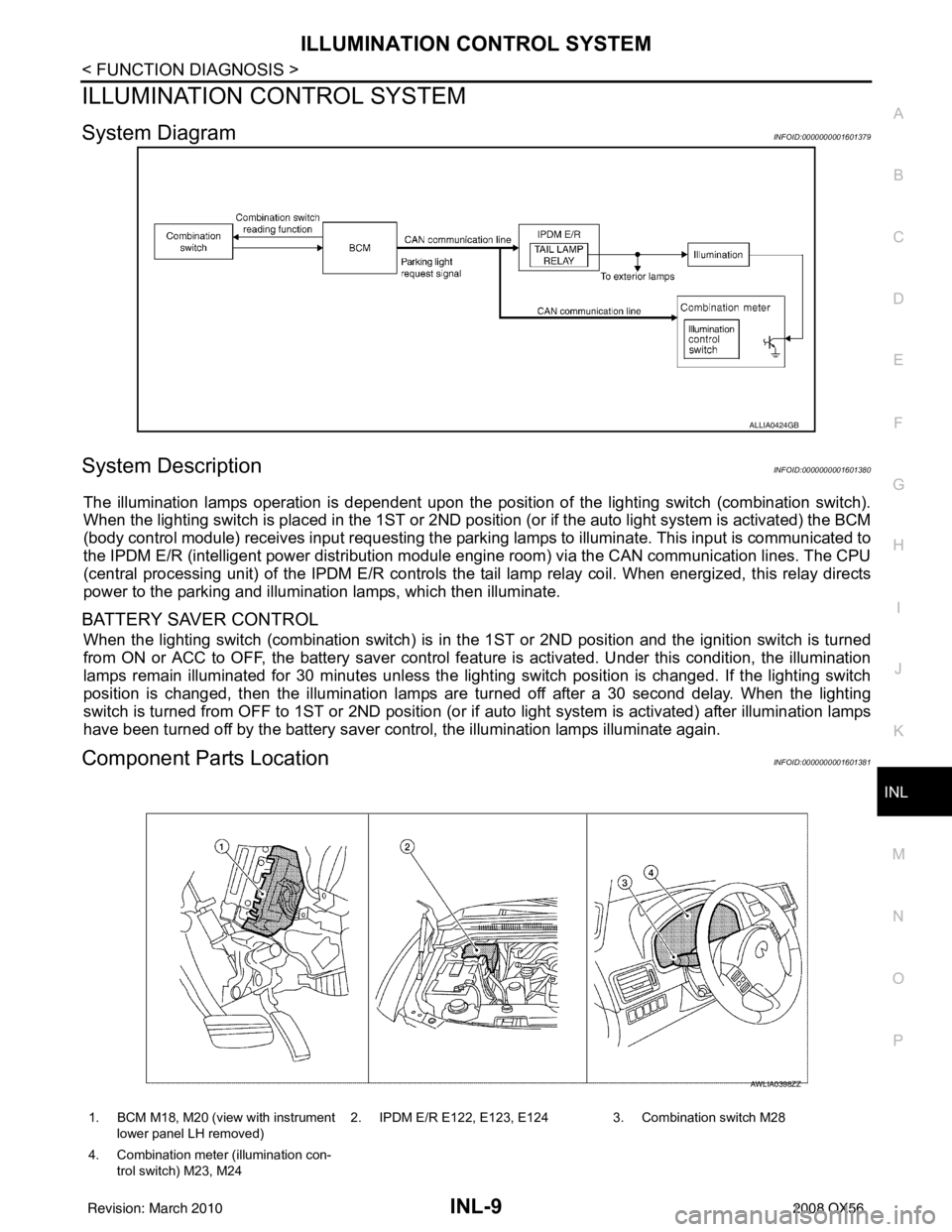
System DiagramINFOID:0000000001601379
System DescriptionINFOID:0000000001601380
The illumination lamps operation is dependent upon the posit ion of the lighting switch (combination switch).
When the lighting switch is placed in the 1ST or 2ND posit ion (or if the auto light system is activated) the BCM
(body control module) receives input requesting the park ing lamps to illuminate. This input is communicated to
the IPDM E/R (intelligent power distribution module engine room) via the CAN communication lines. The CPU
(central processing unit) of the IPDM E/R controls the tail lamp relay coil. When energized, this relay directs
power to the parking and illumination lamps, which then illuminate.
BATTERY SAVER CONTROL
When the lighting switch (combination switch) is in t he 1ST or 2ND position and the ignition switch is turned
from ON or ACC to OFF, the battery saver control feat ure is activated. Under this condition, the illumination
lamps remain illuminated for 30 minutes unless the light ing switch position is changed. If the lighting switch
position is changed, then the illumination lamps are turned off after a 30 second delay. When the lighting
switch is turned from OFF to 1ST or 2ND position (or if auto light system is activated) after illumination lamps
have been turned off by the battery saver control, the illumination lamps illuminate again.
Component Parts LocationINFOID:0000000001601381
ALLIA0424GB
1. BCM M18, M20 (view with instrument
lower panel LH removed) 2. IPDM E/R E122, E123, E124 3. Combination switch M28
4. Combination meter (illumination con- trol switch) M23, M24
AWLIA0398ZZ
Revision: March 2010 2008 QX56
Page 2393 of 4083

INL-10
< FUNCTION DIAGNOSIS >
ILLUMINATION CONTROL SYSTEM
Component Description
INFOID:0000000001601382
Part name Description
BCM The BCM monitors the lighting switch position with the combina-
tion switch reading function. The BCM requests, via CAN com-
munication, that the IPDM E/R activate the tail lamp relay.
IPDM E/R The IPDM E/R activates the tail lamp relay based on inputs re-
ceived from the BCM via the CAN communication network.
Combination meter (illumination control switch) The illumination control switch is a part of the combination meter.
The combination meter controls illumination intensity by varying
ground to the illumination lamps based on the illumination control
switch position.
Combination switch The combination switch provides input to the BCM about the light-
ing switch position.
Revision: March 2010
2008 QX56
Page 2439 of 4083

INL-56
< SYMPTOM DIAGNOSIS >
INTERIOR LIGHTING SYSTEM SYMPTOMS
SYMPTOM DIAGNOSIS
INTERIOR LIGHTING SYSTEM SYMPTOMS
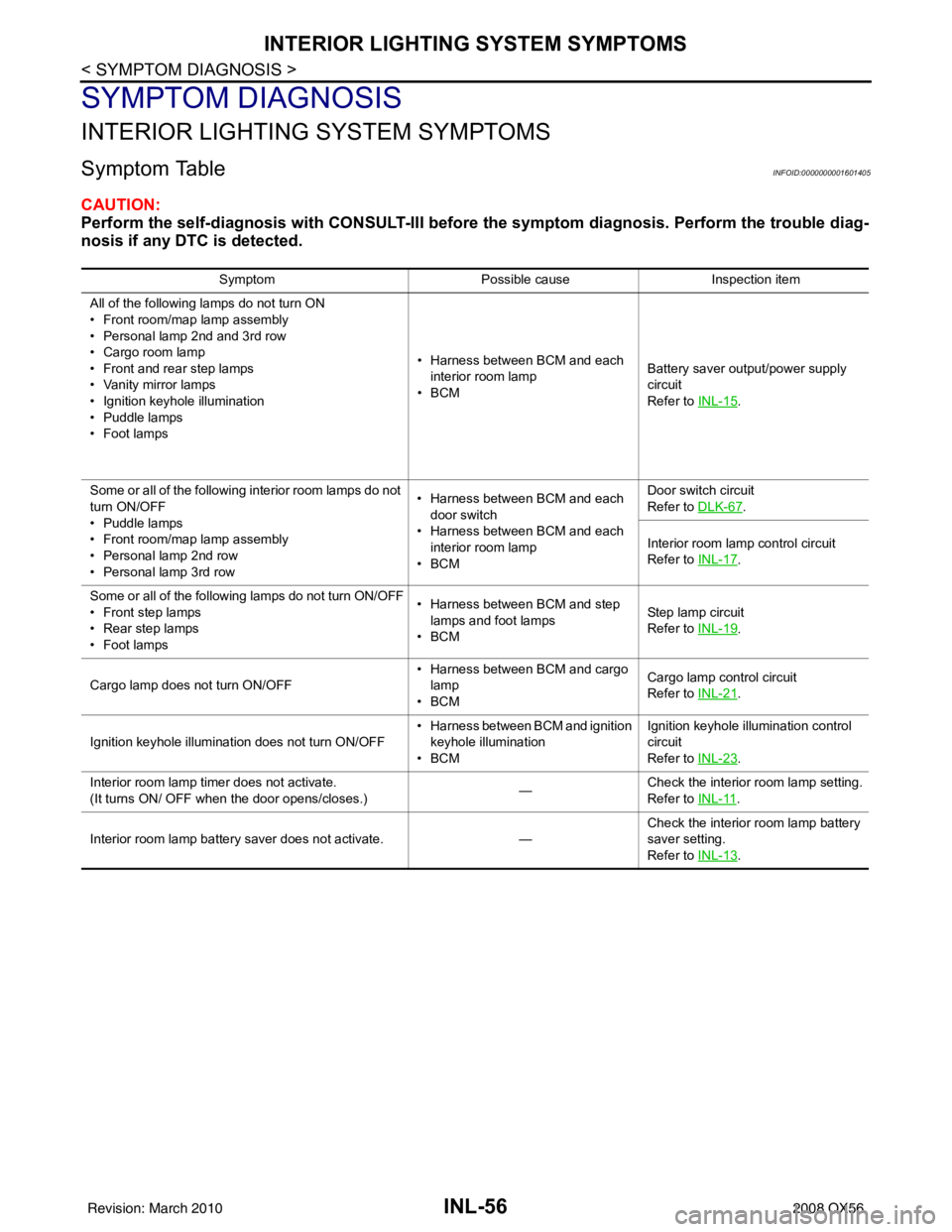
Symptom TableINFOID:0000000001601405
CAUTION:
Perform the self-diagnosis with CONSULT-III before the symptom diagnosis. Perform the trouble diag-
nosis if any DTC is detected.
Symptom Possible causeInspection item
All of the following lamps do not turn ON
• Front room/map lamp assembly
• Personal lamp 2nd and 3rd row
• Cargo room lamp
• Front and rear step lamps
• Vanity mirror lamps
• Ignition keyhole illumination
• Puddle lamps
•Foot lamps • Harness between BCM and each
interior room lamp
•BCM Battery saver output/power supply
circuit
Refer to
INL-15
.
Some or all of the following interior room lamps do not
turn ON/OFF
• Puddle lamps
• Front room/map lamp assembly
• Personal lamp 2nd row
• Personal lamp 3rd row • Harness between BCM and each
door switch
• Harness between BCM and each interior room lamp
•BCM Door switch circuit
Refer to
DLK-67
.
Interior room lamp control circuit
Refer to INL-17
.
Some or all of the following lamps do not turn ON/OFF
• Front step lamps
• Rear step lamps
•Foot lamps • Harness between BCM and step
lamps and foot lamps
•BCM Step lamp circuit
Refer to
INL-19
.
Cargo lamp does not turn ON/OFF • Harness between BCM and cargo
lamp
•BCM Cargo lamp co
ntrol circuit
Refer to INL-21
.
Ignition keyhole illumination does not turn ON/OFF • Harness between BCM and ignition
keyhole illumination
•BCM Ignition keyhole illumination control
circuit
Refer to
INL-23
.
Interior room lamp timer does not activate.
(It turns ON/ OFF when the door opens/closes.) —Check the interior room lamp setting.
Refer to
INL-11
.
Interior room lamp battery saver does not activate. —Check the interior room lamp battery
saver setting.
Refer to
INL-13
.
Revision: March 2010 2008 QX56
Page 2441 of 4083

INL-58
< PRECAUTION >
PRECAUTIONS
5. When the repair work is completed, return the ignition switch to the ″LOCK ″ position before connecting
the battery cables. (At this time, the steering lock mechanism will engage.)
6. Perform a self-diagnosis check of a ll control units using CONSULT-III.
General precautions for service operationsINFOID:0000000001534341
• When removing or disassembling any part, be careful not to damage or deform it. Protect parts which may
get in the way with cloth.
• When removing parts with a screw driver or other tool , protect parts by wrapping them with vinyl or tape.
• Keep removed parts protected with cloth.
• If an non-reuseable part is removed, replace it with a new one.
• After re-assembly has been completed, make sure each part functions correctly.
• Never work with wet hands.
• Turn the lighting switch OFF befor e disconnecting and connecting the connector.
• Do not use organic solvent (paint thinner or gasoline) to clean lamps or remove sealant residue.
Revision: March 2010 2008 QX56
Page 2451 of 4083

INT-2
< SYMPTOM DIAGNOSIS >
SQUEAK AND RATTLE TROUBLE DIAGNOSES
SYMPTOM DIAGNOSIS
SQUEAK AND RATTLE TROUBLE DIAGNOSES
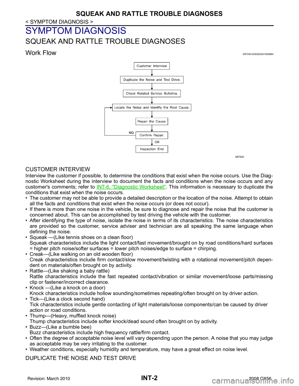
Work FlowINFOID:0000000001609864
CUSTOMER INTERVIEW
Interview the customer if possible, to determine the conditions that exist when the noise occurs. Use the Diag-
nostic Worksheet during the interview to document the facts and conditions when the noise occurs and any
customer's comments; refer to INT-6, "
Diagnostic Worksheet". This information is necessary to duplicate the
conditions that exist when the noise occurs.
• The customer may not be able to provide a detailed description or the location of the noise. Attempt to obtain
all the facts and conditions that exist w hen the noise occurs (or does not occur).
• If there is more than one noise in the vehicle, be sure to diagnose and repair the noise that the customer is
concerned about. This can be accomplished by test driving the vehicle with the customer.
• After identifying the type of noise, isolate the noise in terms of its characteristics. The noise characteristics
are provided so the customer, service adviser and technician are all speaking the same language when
defining the noise.
• Squeak —(Like tennis shoes on a clean floor) Squeak characteristics include the light contact/fast movement/brought on by road conditions/hard surfaces
= higher pitch noise/softer surfaces = lower pitch noises/edge to surface = chirping.
• Creak—(Like walking on an old wooden floor) Creak characteristics include firm contact/slow mo vement/twisting with a rotational movement/pitch depen-
dent on materials/often brought on by activity.
• Rattle—(Like shaking a baby rattle) Rattle characteristics include the fast repeated contac t/vibration or similar movement/loose parts/missing
clip or fastener/incorrect clearance.
• Knock —(Like a knock on a door) Knock characteristics include hollow sounding/someti mes repeating/often brought on by driver action.
• Tick—(Like a clock second hand) Tick characteristics include gentle contacting of light materials/loose components/can be caused by driver
action or road conditions.
• Thump—(Heavy, muffled knock noise)
Thump characteristics include softer k nock/dead sound often brought on by activity.
• Buzz—(Like a bumble bee) Buzz characteristics include hi gh frequency rattle/firm contact.
• Often the degree of acceptable noise level will vary depending upon the person. A noise that you may judge as acceptable may be very irritating to the customer.
• Weather conditions, especially humidity and temperat ure, may have a great effect on noise level.
DUPLICATE THE NOISE AND TEST DRIVE
SBT842
Revision: March 2010 2008 QX56
Page 2452 of 4083

SQUEAK AND RATTLE TROUBLE DIAGNOSESINT-3
< SYMPTOM DIAGNOSIS >
C
DE
F
G H
I
K L
M A
B
INT
N
O P
If possible, drive the vehicle with the customer until the noise is duplicated. Note any additional information on
the Diagnostic Worksheet regarding the conditions or lo cation of the noise. This information can be used to
duplicate the same conditions when you confirm the repair.
If the noise can be duplicated easily during the test drive, to help identify the source of the noise, try to dupli-
cate the noise with the vehicle stopped by doing one or all of the following:
1) Close a door.
2) Tap or push/pull around the area where the noise appears to be coming from.
3) Rev the engine.
4) Use a floor jack to recreate vehicle “twist”.
5) At idle, apply engine load (electrical load, half- clutch on M/T model, drive position on A/T model).
6) Raise the vehicle on a hoist and hit a tire with a rubber hammer.
• Drive the vehicle and attempt to duplicate the conditions the customer states exist when the noise occurs.
• If it is difficult to duplicate the noise, drive the vehicle slowly on an undulating or rough road to stress the vehicle body.
CHECK RELATED SERVICE BULLETINS
After verifying the customer concern or symptom, check ASIST for Technical Service Bulletins (TSBs) related
to that concern or symptom.
If a TSB relates to the symptom, follow the procedure to repair the noise.
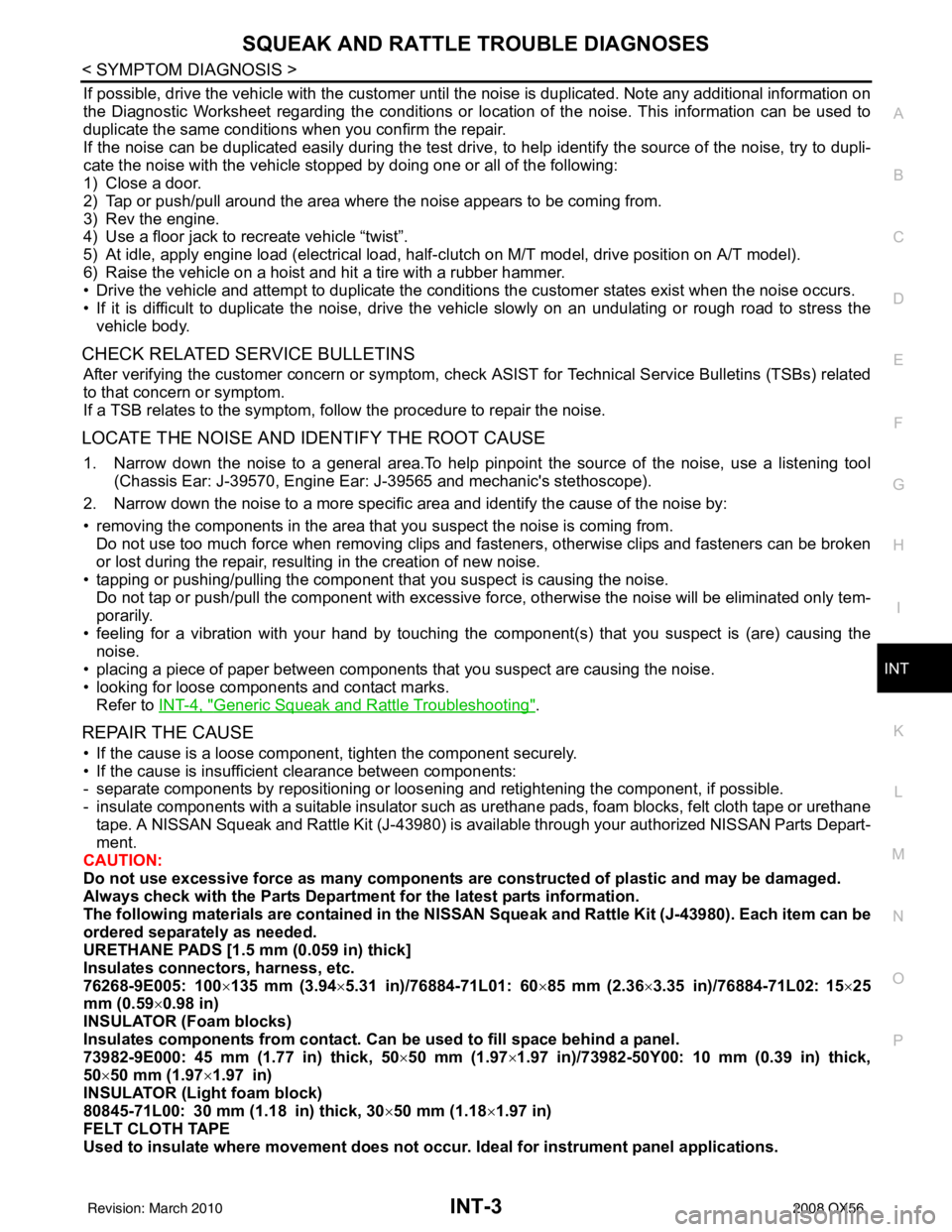
LOCATE THE NOISE AND IDENTIFY THE ROOT CAUSE
1. Narrow down the noise to a general area.To help pinpoint the source of the noise, use a listening tool (Chassis Ear: J-39570, Engine Ear: J-39565 and mechanic's stethoscope).
2. Narrow down the noise to a more specific area and identify the cause of the noise by:
• removing the components in the area that you suspect the noise is coming from. Do not use too much force when removing clips and fasteners, otherwise clips and fasteners can be broken
or lost during the repair, resulting in the creation of new noise.
• tapping or pushing/pulling the component that you suspect is causing the noise.
Do not tap or push/pull the component with excessive force, otherwise the noise will be eliminated only tem-
porarily.
• feeling for a vibration with your hand by touching the component(s) that you suspect is (are) causing the
noise.
• placing a piece of paper between components that you suspect are causing the noise.
• looking for loose components and contact marks. Refer to INT-4, "
Generic Squeak and Rattle Troubleshooting".
REPAIR THE CAUSE
• If the cause is a loose component, tighten the component securely.
• If the cause is insufficient clearance between components:
- separate components by repositioning or loos ening and retightening the component, if possible.
- insulate components with a suitable insulator such as urethane pads, foam blocks, felt cloth tape or urethane tape. A NISSAN Squeak and Rattle Kit (J-43980) is available through your authorized NISSAN Parts Depart-
ment.
CAUTION:
Do not use excessive force as many components are constructed of plastic and may be damaged.
Always check with the Parts Department for the latest parts information.
The following materials are contained in the NISSAN Squeak and Rattle Kit (J-43980). Each item can be
ordered separately as needed.
URETHANE PADS [1.5 mm (0.059 in) thick]
Insulates connectors, harness, etc.
76268-9E005: 100 ×135 mm (3.94 ×5.31 in)/76884-71L01: 60 ×85 mm (2.36× 3.35 in)/76884-71L02: 15× 25
mm (0.59 ×0.98 in)
INSULATOR (Foam blocks)
Insulates components from contact. Can be used to fill space behind a panel.
73982-9E000: 45 mm (1.77 in) thick, 50× 50 mm (1.97×1.97 in)/73982-50Y00: 10 mm (0.39 in) thick,
50× 50 mm (1.97 ×1.97 in)
INSULATOR (Light foam block)
80845-71L00: 30 mm (1.18 in) thick, 30 ×50 mm (1.18 ×1.97 in)
FELT CLOTH TAPE
Used to insulate where movement does not occu r. Ideal for instrument panel applications.
Revision: March 2010 2008 QX56