INFINITI QX56 2008 Factory Service Manual
Manufacturer: INFINITI, Model Year: 2008, Model line: QX56, Model: INFINITI QX56 2008Pages: 4083, PDF Size: 81.73 MB
Page 3541 of 4083
STR-12
< COMPONENT DIAGNOSIS >
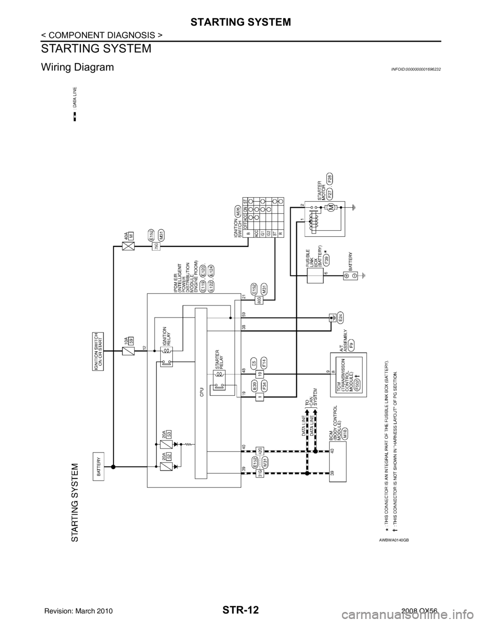
STARTING SYSTEM
STARTING SYSTEM
Wiring DiagramINFOID:0000000001696232
AWBWA0140GB
Revision: March 20102008 QX56
Page 3542 of 4083
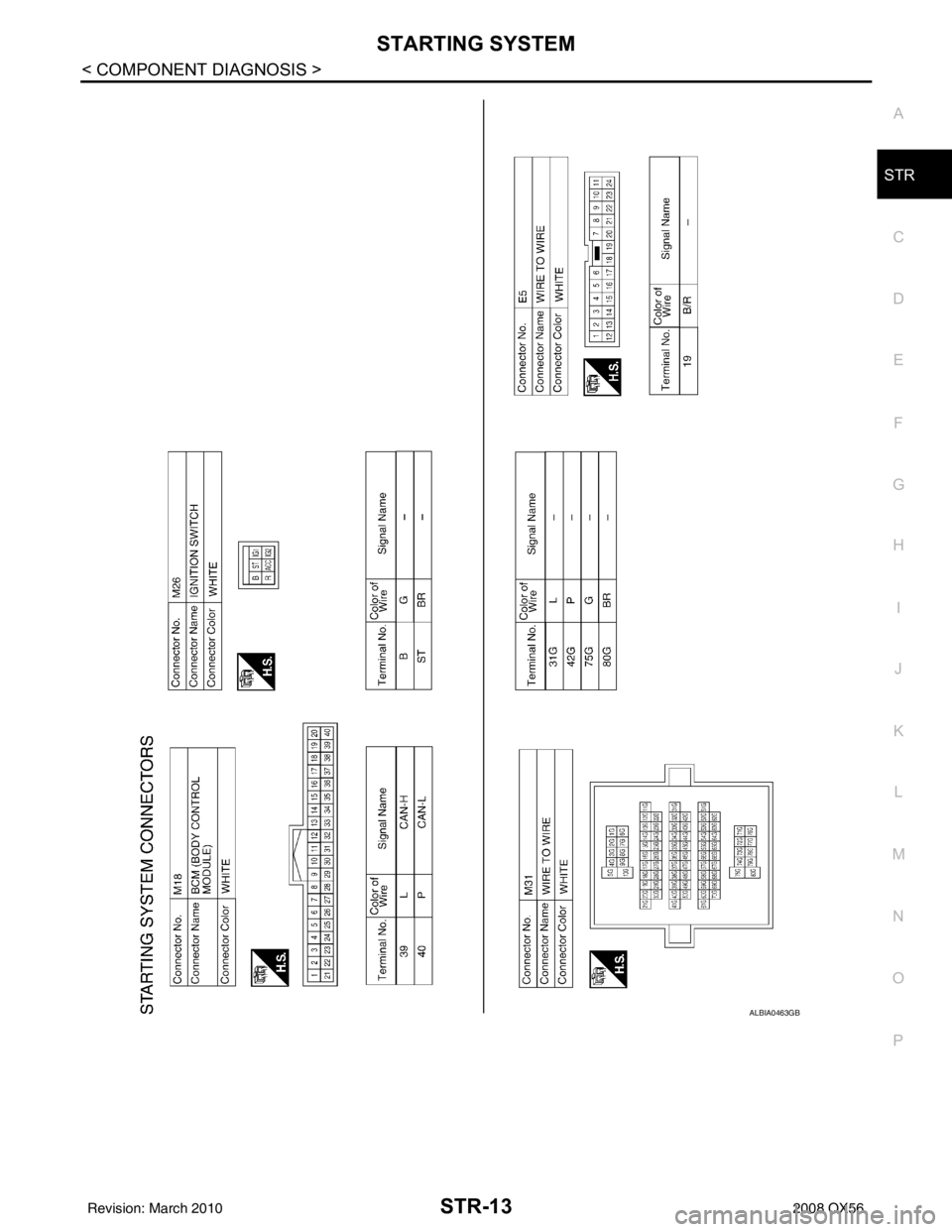
STARTING SYSTEMSTR-13
< COMPONENT DIAGNOSIS >
C
DE
F
G H
I
J
K L
M A
STR
NP
O
ALBIA0463GB
Revision: March 2010
2008 QX56
Page 3543 of 4083
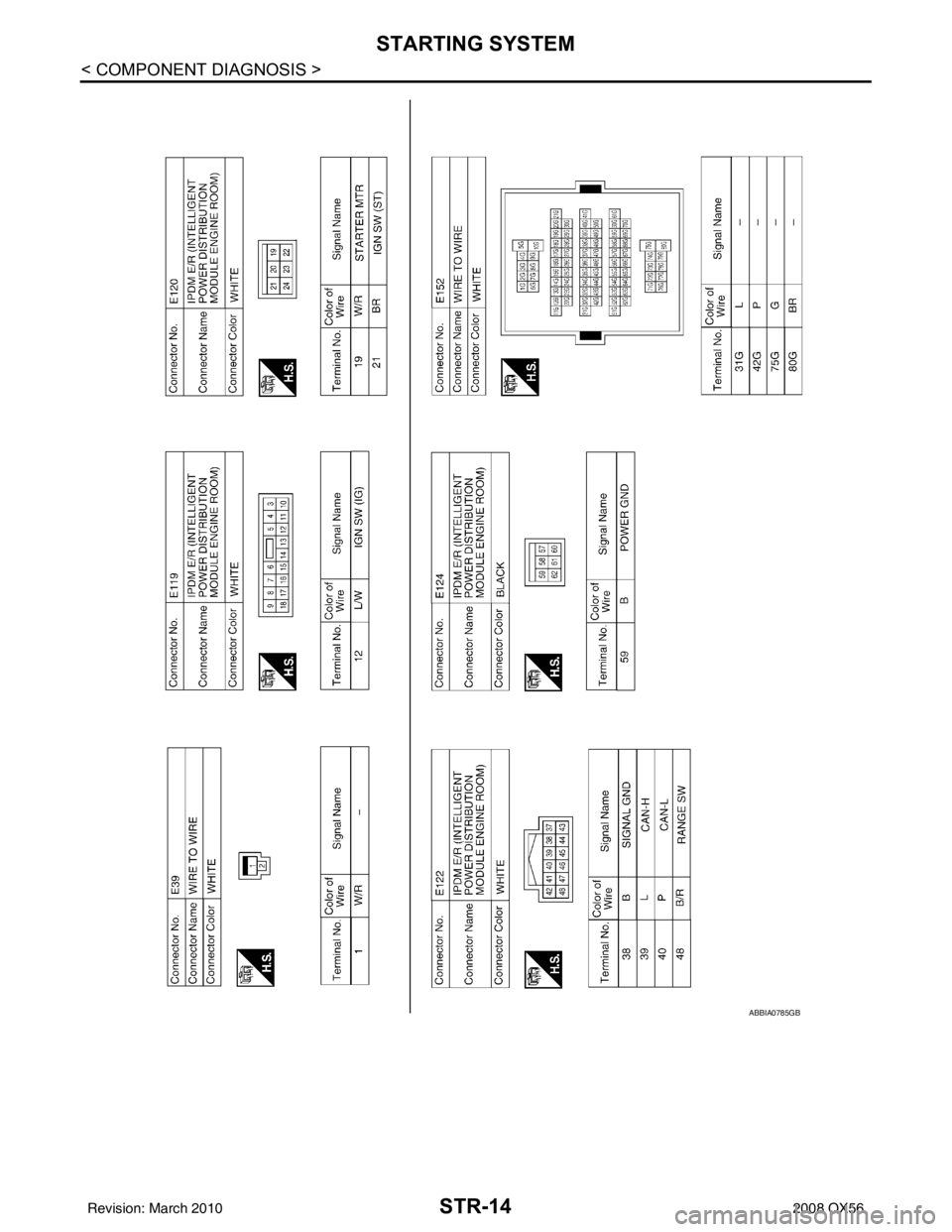
STR-14
< COMPONENT DIAGNOSIS >
STARTING SYSTEM
ABBIA0785GB
Revision: March 20102008 QX56
Page 3544 of 4083
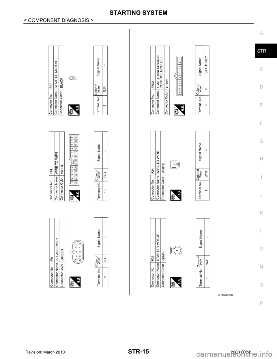
STARTING SYSTEMSTR-15
< COMPONENT DIAGNOSIS >
C
DE
F
G H
I
J
K L
M A
STR
NP
O
ALBIA0465GB
Revision: March 2010
2008 QX56
Page 3545 of 4083
STR-16
< SYMPTOM DIAGNOSIS >
STARTING SYSTEM
SYMPTOM DIAGNOSIS
STARTING SYSTEM
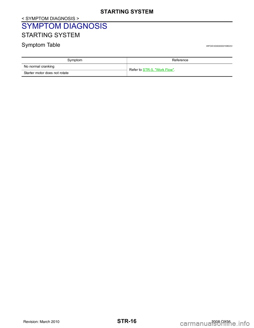
Symptom TableINFOID:0000000001696233
SymptomReference
No normal cranking Refer to STR-5, "
Work Flow".
Starter motor does not rotate
Revision: March 2010 2008 QX56
Page 3546 of 4083
STARTER MOTORSTR-17
< ON-VEHICLE REPAIR >
C
DE
F
G H
I
J
K L
M A
STR
NP
O
ON-VEHICLE REPAIR
STARTER MOTOR
Removal and InstallationINFOID:0000000001538877
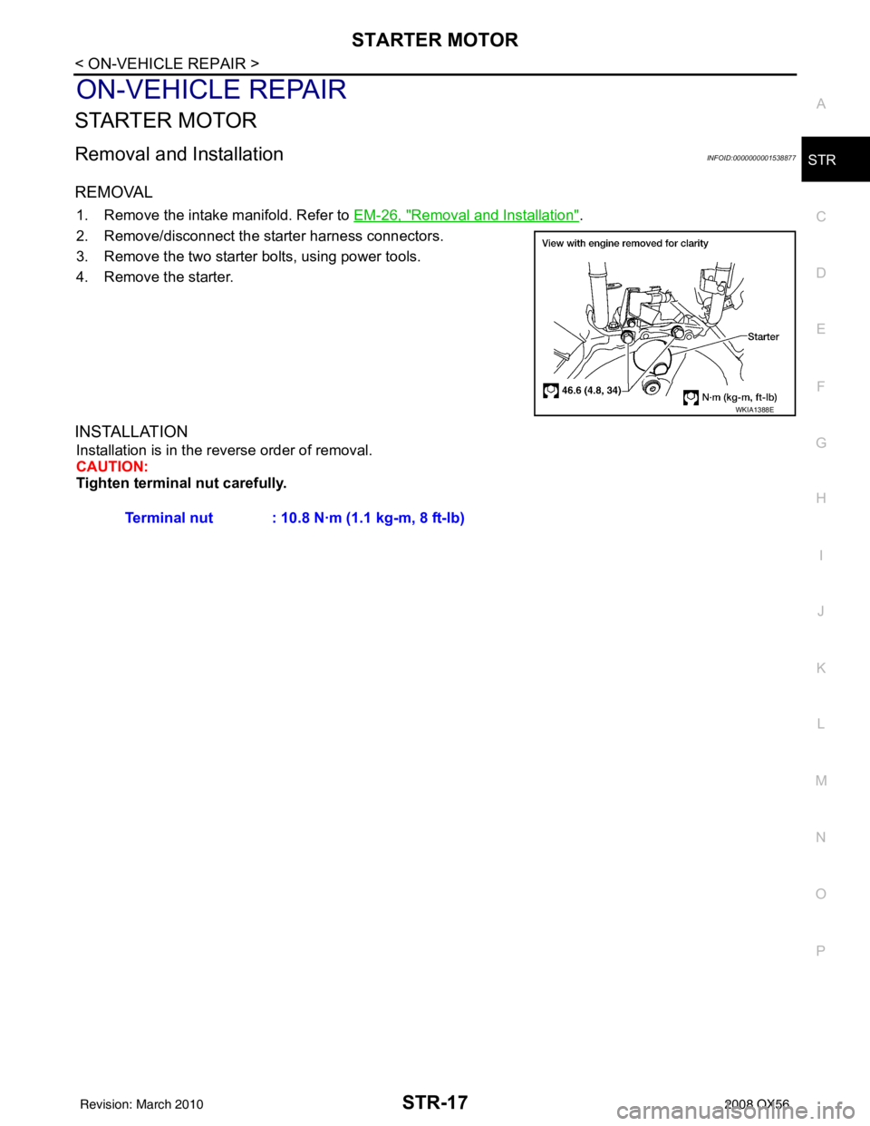
REMOVAL
1. Remove the intake manifold. Refer to
EM-26, "Removal and Installation".
2. Remove/disconnect the starter harness connectors.
3. Remove the two starter bolts, using power tools.
4. Remove the starter.
INSTALLATION
Installation is in the reverse order of removal.
CAUTION:
Tighten terminal nut carefully.
WKIA1388E
Terminal nut : 10.8 N·m (1.1 kg-m, 8 ft-lb)
Revision: March 2010 2008 QX56
Page 3547 of 4083

STR-18
< SERVICE DATA AND SPECIFICATIONS (SDS)
STARTER MOTOR
SERVICE DATA AND SPECIFICATIONS (SDS)
STARTER MOTOR
StarterINFOID:0000000001538878
ApplicationAll models
Manufacturer Mitsubishi
Model number M002T85571ZCKD
Ty p e Reduction gear type
System voltage 12V
No-load Terminal voltage
11V
Current Less than 145A
Revolution More than 3,300 rpm
Minimum diameter of commutator 31.4 mm (1.236 in)
Minimum length of brush 11.0 mm (0.433 in)
Brush spring tension 26.7-36.1 N (2.72 - 3.68 kg, 5.93 - 8.02 lb)
Clearance between pinion front edge and
pinion stopper 0.5 - 2.0 mm (0.020 - 0.079 in)
Revision: March 2010
2008 QX56
Page 3548 of 4083

TM-1
TRANSMISSION & DRIVELINE
CEF
G H
I
J
K L
M
SECTION TM
A
B
TM
N
O P
CONTENTS
TRANSAXLE & TRANSMISSION
BASIC INSPECTION ....... .............................5
DIAGNOSIS AND REPAIR WORKFLOW ..... .....5
Work Flow ........................................................... ......5
Diagnostic Work Sheet ..............................................6
FUNCTION DIAGNOSIS ...............................8
A/T CONTROL SYSTEM ................................ .....8
Cross-Sectional View (2WD models) .................. ......8
Cross-Sectional View (4WD models) ........................9
Shift Mechanism ........................................................9
TCM Function ..........................................................20
CAN Communication ...............................................21
Input/Output Signal of TCM .....................................22
Line Pressure Control .............................................22
Shift Control ........................................................ ....24
Lock-up Control .......................................................25
Engine Brake Control ..............................................26
Control Valve ...........................................................26
Component Parts Location ......................................28
A/T SHIFT LOCK SYSTEM ............................ ....29
System Description ............................................. ....29
Component Parts Location ......................................29
ON BOARD DIAGNOSTIC (OBD) SYSTEM ......30
Introduction ......................................................... ....30
OBD-II Function for A/T System ..............................30
One or Two Trip Detection Logic of OBD-II ............30
OBD-II Diagnostic Trouble Code (DTC) ..................30
Malfunction Indicator Lamp (MIL) ............................31
DIAGNOSIS SYSTEM (TCM) .............................32
CONSULT-III Function (TRANSMISSION) ......... ....32
COMPONENT DIAGNOSIS .........................38
U1000 CAN COMM CI RCUIT .............................38
Description .......................................................... ....38
On Board Diagnosis Logic ......................................38
Possible Cause .......................................................38
DTC Confirmation Procedure .............................. ....38
Diagnosis Procedure ...............................................38
P0615 STARTER RELAY .................................39
Description ...............................................................39
CONSULT-III Reference Value in Data Monitor
Mode .................................................................... ....
39
On Board Diagnosis Logic .......................................39
Possible Cause ........................................................39
DTC Confirmation Procedure ..................................39
Diagnosis Procedure ...............................................39
P0700 TRANSMISSION CONTROL .................42
Description ...............................................................42
On Board Diagnosis Logic .......................................42
Possible Cause ........................................................42
DTC Confirmation Procedure ..................................42
Diagnosis Procedure ...............................................42
P0705 TRANSMISSION RANGE SWITCH A ...43
Description ...............................................................43
CONSULT-III Reference Value in Data Monitor
Mode .................................................................... ....
43
On Board Diagnosis Logic .......................................43
Possible Cause ........................................................43
DTC Confirmation Procedure ..................................43
Diagnosis Procedure ...............................................43
P0717 INPUT SPEED SENSOR A ....................46
Description ...............................................................46
CONSULT-III Reference Value in Data Monitor
Mode .................................................................... ....
46
On Board Diagnosis Logic .......................................46
Possible Cause ........................................................46
DTC Confirmation Procedure ..................................46
Diagnosis Procedure ...............................................46
P0720 OUTPUT SPEED SENSOR ...................48
Description ...............................................................48
CONSULT-III Reference Value in Data Monitor
Mode .................................................................... ....
48
On Board Diagnosis Logic .......................................48
Revision: March 2010 2008 QX56
Page 3549 of 4083

TM-2
Possible Cause .......................................................48
DTC Confirmation Procedure .................................48
Diagnosis Procedure ..............................................49
P0725 ENGINE SPEED .....................................51
Description ........................................................... ...51
CONSULT-III Reference Value in Data Monitor
Mode .................................................................... ...
51
On Board Diagnosis Logic ......................................51
Possible Cause .......................................................51
DTC Confirmation Procedure .................................51
Diagnosis Procedure ..............................................51
P0731 1GR INCORRECT RATIO ......................53
Description ........................................................... ...53
On Board Diagnosis Logic ......................................53
Possible Cause .......................................................53
DTC Confirmation Procedure .................................53
Diagnosis Procedure ..............................................54
P0732 2GR INCORRECT RATIO ......................55
Description ........................................................... ...55
On Board Diagnosis Logic ......................................55
Possible Cause .......................................................55
DTC Confirmation Procedure .................................55
Diagnosis Procedure ..............................................56
P0733 3GR INCORRECT RATIO ......................57
Description ........................................................... ...57
On Board Diagnosis Logic ......................................57
Possible Cause .......................................................57
DTC Confirmation Procedure .................................57
Diagnosis Procedure ..............................................58
P0734 4GR INCORRECT RATIO ......................59
Description ........................................................... ...59
On Board Diagnosis Logic ......................................59
Possible Cause .......................................................59
DTC Confirmation Procedure .................................59
Diagnosis Procedure ..............................................60
P0735 5GR INCORRECT RATIO ......................61
Description ........................................................... ...61
On Board Diagnosis Logic ......................................61
Possible Cause .......................................................61
DTC Confirmation Procedure .................................61
Diagnosis Procedure ..............................................62
P0740 TORQUE CONVERTER .........................63
Description ........................................................... ...63
CONSULT-III Reference Value in Data Monitor
Mode .................................................................... ...
63
On Board Diagnosis Logic ......................................63
Possible Cause .......................................................63
DTC Confirmation Procedure .................................63
Diagnosis Procedure ..............................................63
P0744 TORQUE CONVERTER .........................65
Description ........................................................... ...65
CONSULT-III Reference Value in Data Monitor
Mode .................................................................... ...
65
On Board Diagnosis Logic ................................... ...65
Possible Cause .......................................................65
DTC Confirmation Procedure ..................................65
Diagnosis Procedure ...............................................66
P0745 PRESSURE CONTROL SOLENOID A ...67
Description ........................................................... ...67
CONSULT-III Reference Value in Data Monitor
Mode .................................................................... ...
67
On Board Diagnosis Logic ......................................67
Possible Cause .......................................................67
DTC Confirmation Procedure ..................................67
Diagnosis Procedure ...............................................67
P1705 TP SENSOR ...........................................69
Description ..............................................................69
CONSULT-III Reference Value in Data Monitor
Mode .................................................................... ...
69
On Board Diagnosis Logic ......................................69
Possible Cause .......................................................69
DTC Confirmation Procedure ..................................69
Diagnosis Procedure ...............................................69
P1710 TRANSMISSION FLUID TEMPERA-
TURE SENSOR .................................................
71
Description ........................................................... ...71
CONSULT-III Reference Value in Data Monitor
Mode .................................................................... ...
71
On Board Diagnosis Logic ......................................71
Possible Cause .......................................................71
DTC Confirmation Procedure ..................................71
Diagnosis Procedure ...............................................71
Component Inspection ............................................73
P1721 VEHICLE SPEED SIGNAL ....................74
Description ..............................................................74
CONSULT-III Reference Value in Data Monitor
Mode .................................................................... ...
74
On Board Diagnosis Logic ......................................74
Possible Cause .......................................................74
DTC Confirmation Procedure ..................................74
Diagnosis Procedure ...............................................74
P1730 INTERLOCK ...........................................76
Description ..............................................................76
On Board Diagnosis Logic ......................................76
Possible Cause .......................................................76
DTC Confirmation Procedure ..................................76
Judgement of Interlock ............................................76
Diagnosis Procedure ............................................ ...76
P1731 1ST ENGINE BRAKING .........................78
Description ........................................................... ...78
CONSULT-III Reference Value in Data Monitor
Mode .................................................................... ...
78
On Board Diagnosis Logic ......................................78
Possible Cause .......................................................78
DTC Confirmation Procedure ..................................78
Diagnosis Procedure ...............................................78
Revision: March 2010 2008 QX56
Page 3550 of 4083

TM-3
CEF
G H
I
J
K L
M A
B
TM
N
O P
P1752 INPUT CLUTCH SOLENOID .............. ....80
Description .......................................................... ....80
CONSULT-III Reference Value in Data Monitor
Mode ................................................................... ....
80
On Board Diagnosis Logic ......................................80
Possible Cause .......................................................80
DTC Confirmation Procedure ..................................80
Diagnosis Procedure ...............................................80
P1757 FRONT BRAKE SOLENOID ...................82
Description .......................................................... ....82
CONSULT-III Reference Value in Data Monitor
Mode ................................................................... ....
82
On Board Diagnosis Logic ......................................82
Possible Cause .......................................................82
DTC Confirmation Procedure ..................................82
Diagnosis Procedure ...............................................82
P1762 DIRECT CLUTCH SOLENOID ................84
Description .......................................................... ....84
CONSULT-III Reference Value in Data Monitor
Mode ................................................................... ....
84
On Board Diagnosis Logic ......................................84
Possible Cause .......................................................84
DTC Confirmation Procedure ..................................84
Diagnosis Procedure ...............................................84
P1767 HIGH AND LOW REVERSE CLUTCH
SOLENOID .........................................................
86
Description .......................................................... ....86
CONSULT-III Reference Value in Data Monitor
Mode ................................................................... ....
86
On Board Diagnosis Logic ......................................86
Possible Cause .......................................................86
DTC Confirmation Procedure ..................................86
Diagnosis Procedure ...............................................86
P1772 LOW COAST BRAKE SOLENOID .........88
Description .......................................................... ....88
CONSULT-III Reference Value in Data Monitor
Mode ................................................................... ....
88
On Board Diagnosis Logic ......................................88
Possible Cause .......................................................88
DTC Confirmation Procedure ..................................88
Diagnosis Procedure ...............................................88
P1774 LOW COAST BRAKE SOLENOID .........90
Description .......................................................... ....90
CONSULT-III Reference Value in Data Monitor
Mode ................................................................... ....
90
On Board Diagnosis Logic ......................................90
Possible Cause .......................................................90
DTC Confirmation Procedure ..................................90
Diagnosis Procedure ...............................................90
MAIN POWER SUPPLY AND GROUND CIR-
CUIT ....................................................................
92
Diagnosis Procedure ........................................... ....92
CLOSED THROTTLE POSITION AND WIDE
OPEN THROTTLE POSITION CIRCUIT ...........
94
CONSULT-III Reference Value in Data Monitor
Mode .................................................................... ....
94
Diagnosis Procedure ...............................................94
BRAKE SIGNAL CIRCUIT ................................95
CONSULT-III Reference Va lue in Data Monitor
Mode .................................................................... ....
95
Diagnosis Procedure ...............................................95
TOW MODE SWITCH .......................................96
Description ...............................................................96
Diagnosis Procedure ...............................................96
A/T SHIFT LOCK SYSTEM ...............................97
Wiring Diagram - A/T Shift Lock System .................97
Terminals And Reference Values ..........................100
Component Description ....................................... ..100
ECU DIAGNOSIS .......................................103
TCM .................................................................103
Reference Value .................................................. ..103
Wiring Diagram — A/T CONTROL SYSTEM — .. ..105
Fail-Safe .............................................................. ..114
DTC Inspection Priority Chart ................................116
DTC No. Index .......................................................116
DTC Alphabetical Index .........................................117
SYMPTOM DIAGNOSIS ............................118
SYSTEM SYMPTOM .......................................118
A/T Check Indicator Lamp Does Not Come On ... ..118
Engine Cannot Be Started in "P" or "N" Position ...118
In "P" Position, Vehicle Moves When Pushed .......119
In "N" Position, Vehicle Moves ..............................119
Large Shock("N" to "D" Position) ...........................121
Vehicle Does Not Creep Backward in "R" Position ..123
Vehicle Does Not Creep Forward in "D" Position ..125
Vehicle Cannot Be Started from D1 ......................128
A/T Does Not Shift: D1→D2 ..................................130
A/T Does Not Shift: D2→ D3 ..................................131
A/T Does Not Shift: D3→ D4 ..................................133
A/T Does Not Shift: D4→ D5 ..................................135
A/T Does Not Perform Lock-up ........................... ..137
A/T Does Not Hold Lock-up Condition ...................139
Lock-up Is Not Released .......................................140
Engine Speed Does Not Return to Idle .................141
A/T Does Not Shift: 5GR → 4GR ........................ ..142
A/T Does Not Shift: 4GR → 3GR ........................ ..144
A/T Does Not Shift: 3GR → 2GR ........................ ..146
A/T Does Not Shift: 2GR → 1GR ........................ ..147
Vehicle Does Not Decelerate By Engine Brake ... ..149
Symptom Table .....................................................151
PRECAUTION ............................................173
PRECAUTIONS ...............................................173
Revision: March 2010 2008 QX56