lock INFINITI QX56 2008 Factory Service Manual
[x] Cancel search | Manufacturer: INFINITI, Model Year: 2008, Model line: QX56, Model: INFINITI QX56 2008Pages: 4083, PDF Size: 81.73 MB
Page 3624 of 4083

P1730 INTERLOCKTM-77
< COMPONENT DIAGNOSIS >
CEF
G H
I
J
K L
M A
B
TM
N
O P
• Refer to TM-76, "DTC Confirmation Procedure".
OK or NG
OK >> INSPECTION END
NG >> GO TO 3.
3.CHECK TCM POWER SUPPLY AND GROUND CIRCUIT
Check TCM power supply and ground circuit. Refer to TM-92, "
Diagnosis Procedure".
OK or NG
OK >> GO TO 4.
NG >> Repair or replace damaged parts.
4.DETECT MALFUNCTIONING ITEM
Check the following items:
• The A/T assembly harness connector pin terminals for damage or loose connection with harness connector.
OK or NG
OK >> Replace the control valve with TCM. Refer to TM-201, "Control Valve with TCM and A/T Fluid
Temperature Sensor 2".
NG >> Repair or replace damaged parts.
Revision: March 2010 2008 QX56
Page 3639 of 4083
TM-92
< COMPONENT DIAGNOSIS >
MAIN POWER SUPPLY AND GROUND CIRCUIT
MAIN POWER SUPPLY AND GROUND CIRCUIT
Diagnosis ProcedureINFOID:0000000001604160
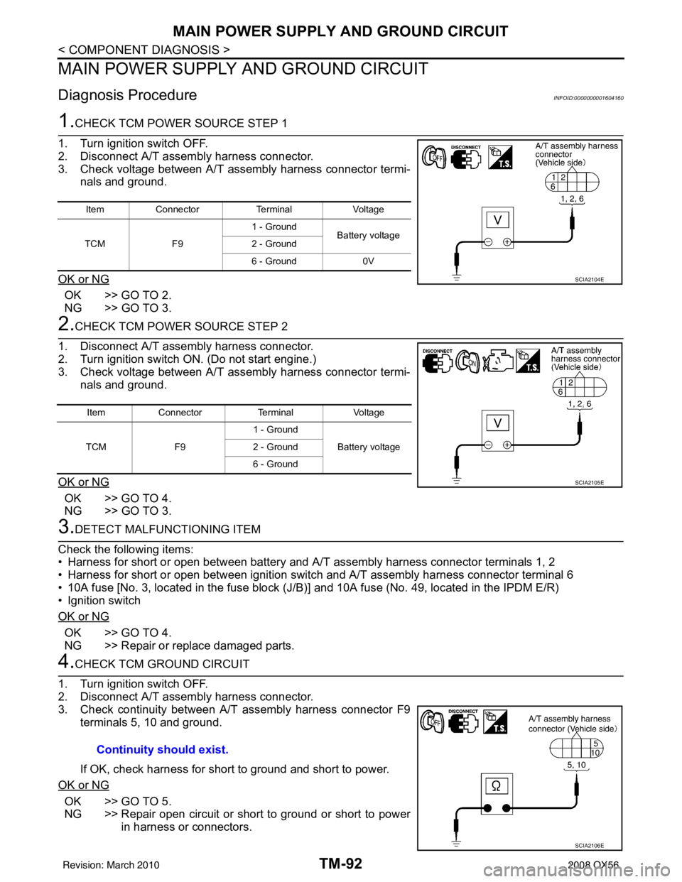
1.CHECK TCM POWER SOURCE STEP 1
1. Turn ignition switch OFF.
2. Disconnect A/T assembly harness connector.
3. Check voltage between A/T assembly harness connector termi- nals and ground.
OK or NG
OK >> GO TO 2.
NG >> GO TO 3.
2.CHECK TCM POWER SOURCE STEP 2
1. Disconnect A/T assembly harness connector.
2. Turn ignition switch ON. (Do not start engine.)
3. Check voltage between A/T assembly harness connector termi- nals and ground.
OK or NG
OK >> GO TO 4.
NG >> GO TO 3.
3.DETECT MALFUNCTIONING ITEM
Check the following items:
• Harness for short or open between battery and A/T assembly harness connector terminals 1, 2
• Harness for short or open between ignition switch and A/T assembly harness connector terminal 6
• 10A fuse [No. 3, located in the fuse block (J/B )] and 10A fuse (No. 49, located in the IPDM E/R)
• Ignition switch
OK or NG
OK >> GO TO 4.
NG >> Repair or replace damaged parts.
4.CHECK TCM GROUND CIRCUIT
1. Turn ignition switch OFF.
2. Disconnect A/T assembly harness connector.
3. Check continuity between A/T assembly harness connector F9 terminals 5, 10 and ground.
If OK, check harness for short to ground and short to power.
OK or NG
OK >> GO TO 5.
NG >> Repair open circuit or short to ground or short to power in harness or connectors.
Item Connector TerminalVoltage
TCM F91 - Ground
Battery voltage
2 - Ground
6 - Ground 0V
SCIA2104E
ItemConnector TerminalVoltage
TCM F91 - Ground
Battery voltage
2 - Ground
6 - Ground
SCIA2105E
Continuity should exist.
SCIA2106E
Revision: March 2010 2008 QX56
Page 3644 of 4083

A/T SHIFT LOCK SYSTEMTM-97
< COMPONENT DIAGNOSIS >
CEF
G H
I
J
K L
M A
B
TM
N
O P
A/T SHIFT LOCK SYSTEM
Wiring Diagram - A/ T Shift Lock SystemINFOID:0000000001696153
ABDWA0334GB
Revision: March 2010 2008 QX56
Page 3645 of 4083

TM-98
< COMPONENT DIAGNOSIS >
A/T SHIFT LOCK SYSTEM
AADIA0077GB
Revision: March 20102008 QX56
Page 3646 of 4083

A/T SHIFT LOCK SYSTEMTM-99
< COMPONENT DIAGNOSIS >
CEF
G H
I
J
K L
M A
B
TM
N
O P
ABDIA0628GB
Revision: March 2010 2008 QX56
Page 3647 of 4083
TM-100
< COMPONENT DIAGNOSIS >
A/T SHIFT LOCK SYSTEM
Terminals And Reference Values
INFOID:0000000001604171
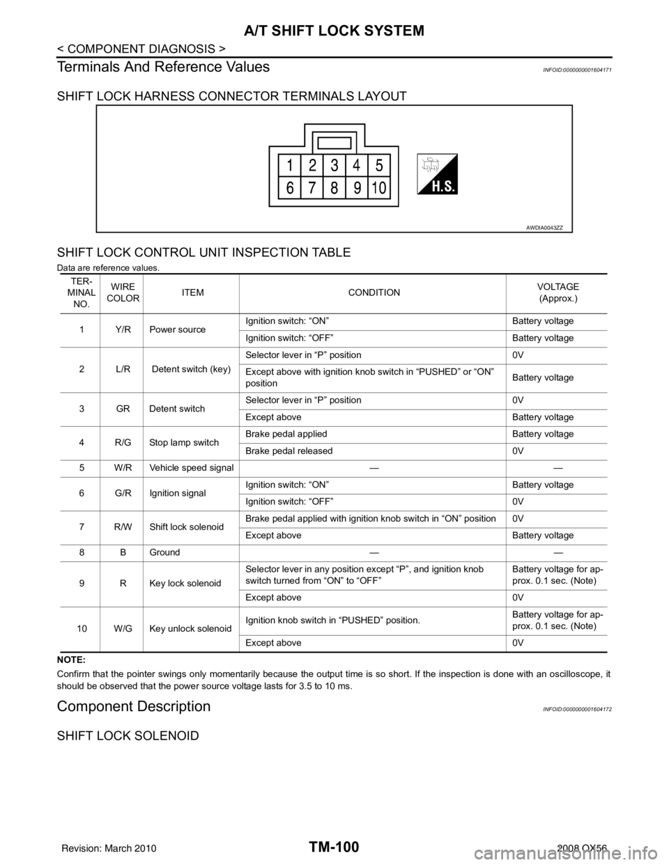
SHIFT LOCK HARNESS CONNECTOR TERMINALS LAYOUT
SHIFT LOCK CONTROL UNIT INSPECTION TABLE
Data are reference values.
NOTE:
Confirm that the pointer swings only momentarily because the output time is so short. If the inspection is done with an oscillo scope, it
should be observed that the power source voltage lasts for 3.5 to 10 ms.
Component DescriptionINFOID:0000000001604172
SHIFT LOCK SOLENOID
AWDIA0043ZZ
TER-
MINAL NO. WIRE
COLOR ITEM
CONDITION VOLTAGE
(Approx.)
1Y/RPower source Ignition switch: “ON”
Battery voltage
Ignition switch: “OFF” Battery voltage
2 L/R Detent switch (key) Selector lever in “P” position
0V
Except above with ignition knob switch in “PUSHED” or “ON”
position Battery voltage
3GRDetent switch Selector lever in “P” position
0V
Except above Battery voltage
4 R/G Stop lamp switch Brake pedal applied
Battery voltage
Brake pedal released 0V
5 W/R Vehicle speed signal ——
6 G/R Ignition signal Ignition switch: “ON”
Battery voltage
Ignition switch: “OFF” 0V
7 R/W Shift lock solenoid Brake pedal applied with ignition knob switch in “ON” position 0V
Except above
Battery voltage
8 B Ground ——
9 R Key lock solenoid Selector lever in any position except “P”, and ignition knob
switch turned from “ON” to “OFF”
Battery voltage for ap-
prox. 0.1 sec. (Note)
Except above 0V
10 W/G Key unlock solenoid Ignition knob switch in “PUSHED” position.
Battery voltage for ap-
prox. 0.1 sec. (Note)
Except above 0V
Revision: March 2010 2008 QX56
Page 3648 of 4083
A/T SHIFT LOCK SYSTEMTM-101
< COMPONENT DIAGNOSIS >
CEF
G H
I
J
K L
M A
B
TM
N
O P
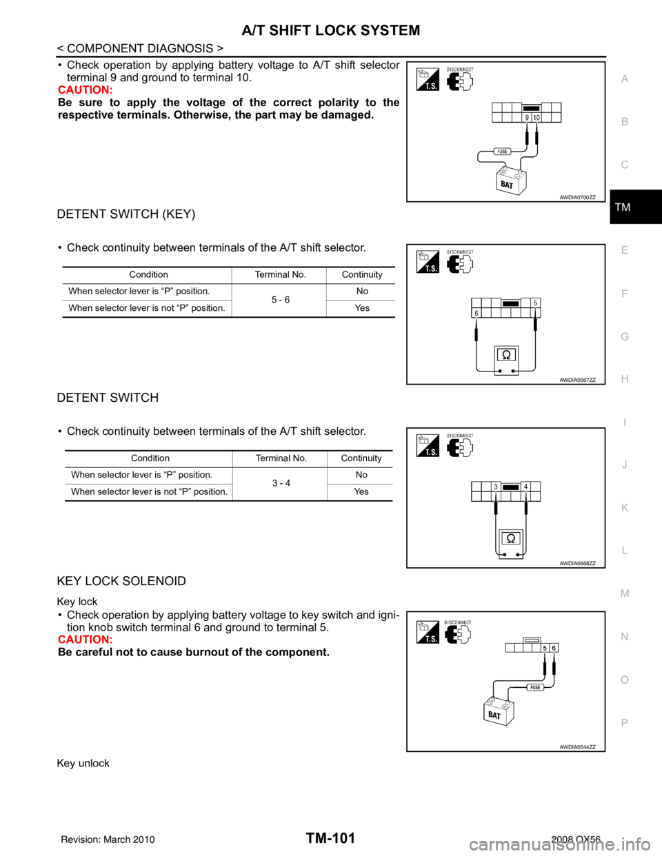
• Check operation by applying battery voltage to A/T shift selector terminal 9 and ground to terminal 10.
CAUTION:
Be sure to apply the voltage of the correct polarity to the
respective terminals. Otherwise, the part may be damaged.
DETENT SWITCH (KEY)
• Check continuity between terminals of the A/T shift selector.
DETENT SWITCH
• Check continuity between terminals of the A/T shift selector.
KEY LOCK SOLENOID
Key lock
• Check operation by applying battery voltage to key switch and igni-
tion knob switch terminal 6 and ground to terminal 5.
CAUTION:
Be careful not to cause burnout of the component.
Key unlock
AWDIA0700ZZ
Condition Terminal No. Continuity
When selector lever is “P” position. 5 - 6No
When selector lever is not “P” position. Yes
AWDIA0567ZZ
ConditionTerminal No. Continuity
When selector lever is “P” position. 3 - 4No
When selector lever is not “P” position. Yes
AWDIA0568ZZ
AWDIA0544ZZ
Revision: March 2010 2008 QX56
Page 3649 of 4083
TM-102
< COMPONENT DIAGNOSIS >
A/T SHIFT LOCK SYSTEM
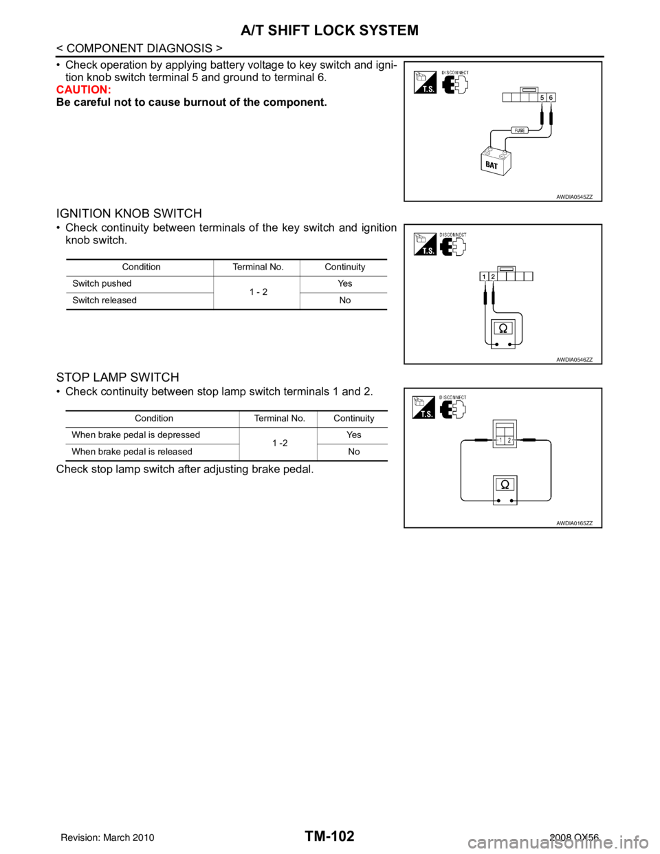
• Check operation by applying battery voltage to key switch and igni-tion knob switch terminal 5 and ground to terminal 6.
CAUTION:
Be careful not to cause burnout of the component.
IGNITION KNOB SWITCH
• Check continuity between terminals of the key switch and ignition
knob switch.
STOP LAMP SWITCH
• Check continuity between stop lamp switch terminals 1 and 2.
Check stop lamp switch after adjusting brake pedal.
AWDIA0545ZZ
Condition Terminal No. Continuity
Switch pushed 1 - 2Ye s
Switch released No
AWDIA0546ZZ
ConditionTerminal No. Continuity
When brake pedal is depressed 1 -2Ye s
When brake pedal is released No
AWDIA0165ZZ
Revision: March 2010 2008 QX56
Page 3650 of 4083
TCM
TM-103
< ECU DIAGNOSIS >
C EF
G H
I
J
K L
M A
B
TM
N
O P
ECU DIAGNOSIS
TCM
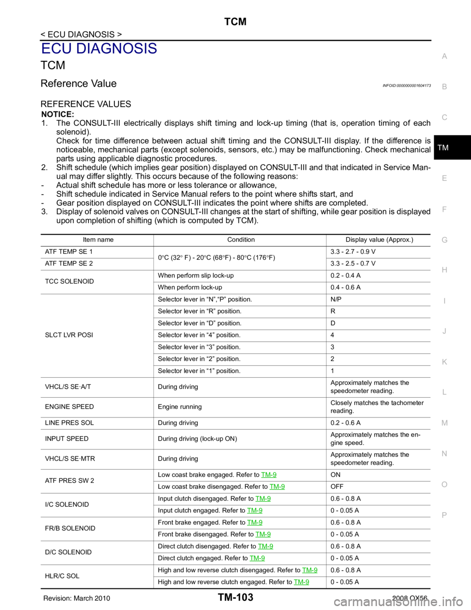
Reference ValueINFOID:0000000001604173
REFERENCE VALUES
NOTICE:
1. The CONSULT-III electrically displays shift timi ng and lock-up timing (that is, operation timing of each
solenoid).
Check for time difference between actual shift timi ng and the CONSULT-III display. If the difference is
noticeable, mechanical parts (except solenoids, sens ors, etc.) may be malfunctioning. Check mechanical
parts using applicable diagnostic procedures.
2. Shift schedule (which implies gear position) display ed on CONSULT-III and that indicated in Service Man-
ual may differ slightly. This occurs because of the following reasons:
- Actual shift schedule has more or less tolerance or allowance,
- Shift schedule indicated in Service Manual re fers to the point where shifts start, and
- Gear position displayed on CONSULT-III indicates the point where shifts are completed.
3. Display of solenoid valves on CONSULT-III changes at the start of shifting, while gear position is displayed upon completion of shifting (which is computed by TCM).
Item name Condition Display value (Approx.)
ATF TEMP SE 1 0°C (32 ° F) - 20 °C (68 °F) - 80 °C (176 °F) 3.3 - 2.7 - 0.9 V
ATF TEMP SE 2 3.3 - 2.5 - 0.7 V
TCC SOLENOID When perform slip lock-up
0.2 - 0.4 A
When perform lock-up 0.4 - 0.6 A
SLCT LVR POSI Selector lever in
“N”,“P” position. N/P
Selector lever in “R” position. R
Selector lever in “D” position. D
Selector lever in “4” position. 4
Selector lever in “3” position. 3
Selector lever in “2” position. 2
Selector lever in “1” position. 1
VHCL/S SE·A/T During driving Approximately matches the
speedometer reading.
ENGINE SPEED Engine running Closely matches the tachometer
reading.
LINE PRES SOL During driving 0.2 - 0.6 A
INPUT SPEED During driving (lock-up ON) Approximately matches the en-
gine speed.
VHCL/S SE·MTR During driving Approximately matches the
speedometer reading.
ATF PRES SW 2 Low coast brake engaged. Refer to
TM-9
ON
Low coast brake disengaged. Refer to TM-9
OFF
I/C SOLENOID Input clutch disengaged. Refer to
TM-9
0.6 - 0.8 A
Input clutch engaged. Refer to TM-9
0 - 0.05 A
FR/B SOLENOID Front brake engaged. Refer to
TM-9
0.6 - 0.8 A
Front brake disengaged. Refer to TM-9
0 - 0.05 A
D/C SOLENOID Direct clutch disengaged. Refer to
TM-9
0.6 - 0.8 A
Direct clutch engaged. Refer to TM-9
0 - 0.05 A
HLR/C SOL High and low reverse clutch disengaged. Refer to
TM-9
0.6 - 0.8 A
High and low reverse clutch engaged. Refer to TM-9
0 - 0.05 A
Revision: March 2010 2008 QX56
Page 3662 of 4083

TCM
TM-115
< ECU DIAGNOSIS >
C EF
G H
I
J
K L
M A
B
TM
N
O P
Even when the electronic circuits are normal, under s pecial conditions (for example, when slamming on the
brake with the wheels spinning drastically and stopping the tire rotation), the transmission can go into fail-safe
mode. If this happens, switch “OFF” the ignition switch for 10 seconds, then switch it “ON” again to return to
the normal shift pattern. Therefore, the customer's vehicle has returned to normal, so handle according to the
“diagnostics flow” (Refer to TM-5, "
Work Flow").
FAIL-SAFE FUNCTION
If any malfunction occurs in a sensor or solenoid, th is function controls the A/T to mark driving possible.
Output Speed Sensor
• Signals are input from two systems - from output s peed sensor installed on the transmission and from com-
bination meter so normal driving is possible even if t here is a malfunction in one of the systems. And if output
speed sensor has unusual cases, 5GR is prohibited.
Accelerator Pedal Position Sensor
• If there is a malfunction in one of the systems, the accelerator opening angle is controlled by ECM according
to a pre-determined accelerator angle to make driving possible. And if there are malfunctions in tow sys-
tems, the engine speed is fixed by ECM to a pre-determined engine speed to make driving possible.
Throttle Position Sensor
• If there is a malfunction in one of the systems, the accelerator opening angle is controlled by ECM according
to a pre-determined accelerator angle to make driving possible. And if there are malfunctions in tow sys-
tems, the accelerator opening angle is controlled by the idle signal sent from the ECM which is based on
input indicating either idle condition or off-idle condition (pre-determined accelerator opening) in order to
make driving possible.
Transmission Range Switch
• In the unlikely event that a malfunction signal enters t he TCM, the position indicator is switched “OFF”, the
starter relay is switched “OFF” (starter starting is disabled), the back-up lamp relay switched “OFF” (back-up
lamp is OFF) and the position is fixed to the “D” range to make driving possible.
Starter Relay
• The starter relay is switched “OFF”. (Starter starting is disabled.)
Interlock
• If there is an interlock judgment malfunction, the tr ansmission is fixed in 2GR to make driving possible.
NOTE:
When the vehicle is driven fixed in 2GR, a inpu t speed sensor malfunction is displayed, but this is
not a input speed sensor malfunction.
• When the interlock is detected at the 3GR or more, it is locked at the 2GR.
1st Engine Braking
• When there is an 1st engine brake judgment malfunction, the low coast brake solenoid is switched “OFF” to
avoid the engine brake operation.
Line Pressure Solenoid
• The solenoid is switched “OFF” and the line pressure is set to the maximum hydraulic pressure to make driv- ing possible.
Torque Converter Clutch Solenoid
• The solenoid is switched “OFF” to release the lock-up.
Low Coast Brake Solenoid
• When a (electrical or functional) malfunction occurs, in order to make driving possible, the engine brake is
not applied in 1GR and 2GR.
Input Clutch Solenoid
• If a (electrical or functional) malfunction occurs with the solenoid either “ON” or “OFF”, the transmission is
held in 4th gear to make driving possible.
Direct Clutch Solenoid
• If a (electrical or functional) malfunction occurs with the solenoid either “ON” or “OFF”, the transmission is
held in 4GR to make driving possible.
Front Brake Solenoid
• If a (electrical or functional) malfunction occurs with the solenoid “ON”, in order to make driving possible, the
A/T is held in 5GR; if the solenoid is OFF, 4GR.
Revision: March 2010 2008 QX56