ignition INFINITI QX56 2008 Factory Service Manual
[x] Cancel search | Manufacturer: INFINITI, Model Year: 2008, Model line: QX56, Model: INFINITI QX56 2008Pages: 4083, PDF Size: 81.73 MB
Page 10 of 4083

ACC-2
< PRECAUTION >
PRECAUTIONS
PRECAUTION
PRECAUTIONS
Precaution for Supplemental Restraint System (SRS) "AIR BAG" and "SEAT BELT
PRE-TENSIONER"
INFOID:0000000004874943
The Supplemental Restraint System such as “A IR BAG” and “SEAT BELT PRE-TENSIONER”, used along
with a front seat belt, helps to reduce the risk or severity of injury to the driver and front passenger for certain
types of collision. This system includes seat belt switch inputs and dual stage front air bag modules. The SRS
system uses the seat belt switches to determine the front air bag deployment, and may only deploy one front
air bag, depending on the severity of a collision and w hether the front occupants are belted or unbelted.
Information necessary to service the system safely is included in the SR and SB section of this Service Man-
ual.
WARNING:
• To avoid rendering the SRS inopera tive, which could increase the risk of personal injury or death in
the event of a collision which would result in air bag inflation, all maintenance must be performed by
an authorized NISSAN/INFINITI dealer.
• Improper maintenance, including in correct removal and installation of the SRS, can lead to personal
injury caused by unintent ional activation of the system. For re moval of Spiral Cable and Air Bag
Module, see the SR section.
• Do not use electrical test equipmen t on any circuit related to the SRS unless instructed to in this
Service Manual. SRS wiring harn esses can be identified by yellow and/or orange harnesses or har-
ness connectors.
PRECAUTIONS WHEN USING POWER TOOLS (AIR OR ELECTRIC) AND HAMMERS
WARNING:
• When working near the Airbag Diagnosis Sensor Unit or other Airbag System sensors with the Igni-
tion ON or engine running, DO NOT use air or electri c power tools or strike near the sensor(s) with a
hammer. Heavy vibration could activate the sensor( s) and deploy the air bag(s), possibly causing
serious injury.
• When using air or electric power tools or hammers , always switch the Ignition OFF, disconnect the
battery, and wait at least 3 minu tes before performing any service.
Precaution Necessary for Steering W heel Rotation After Battery Disconnect
INFOID:0000000004874942
NOTE:
• This Procedure is applied only to models with Intelligent Key system and NATS (NISSAN ANTI-THEFT SYS-
TEM).
• Remove and install all control units after disconnecting both battery cables with the ignition knob in the
″LOCK ″ position.
• Always use CONSULT-III to perform self-diagnosis as a part of each function inspection after finishing work.
If DTC is detected, perform trouble diagnosis according to self-diagnostic results.
For models equipped with the Intelligent Key system and NATS, an electrically controlled steering lock mech-
anism is adopted on the key cylinder.
For this reason, if the battery is disconnected or if the battery is discharged, the steering wheel will lock and
steering wheel rotation will become impossible.
If steering wheel rotation is required when battery pow er is interrupted, follow the procedure below before
starting the repair operation.
OPERATION PROCEDURE
1. Connect both battery cables. NOTE:
Supply power using jumper cables if battery is discharged.
2. Use the Intelligent Key or mechanical key to turn the ignition switch to the ″ACC ″ position. At this time, the
steering lock will be released.
3. Disconnect both battery cables. The steering lock will remain released and the steering wheel can be rotated.
4. Perform the necessary repair operation.
Revision: March 2010 2008 QX56
Page 11 of 4083

PRECAUTIONSACC-3
< PRECAUTION >
C
DE
F
G H
I
J
K L
M A
ACC
NP
O
5. When the repair work is completed, return the ignition switch to the
″LOCK ″ position before connecting
the battery cables. (At this time, the steering lock mechanism will engage.)
6. Perform a self-diagnosis check of al l control units using CONSULT-III.
Revision: March 2010 2008 QX56
Page 12 of 4083

ACC-4
< REMOVAL AND INSTALLATION >
ACCELERATOR CONTROL SYSTEM
REMOVAL AND INSTALLATION
ACCELERATOR CONTROL SYSTEM
Removal and InstallationINFOID:0000000001534441
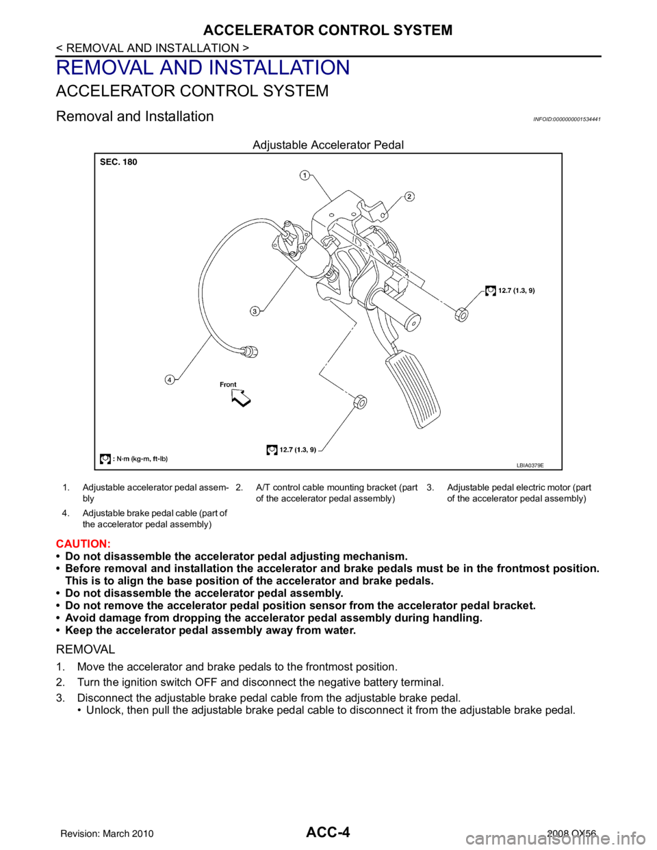
Adjustable Accelerator Pedal
CAUTION:
• Do not disassemble the accelerator pedal adjusting mechanism.
• Before removal and installation the accelerator and brake pedals must be in the frontmost position.
This is to align the base position of the accelerator and brake pedals.
• Do not disassemble the accelerator pedal assembly.
• Do not remove the accelerator pedal position sensor from the accelerator pedal bracket.
• Avoid damage from dropping the accel erator pedal assembly during handling.
• Keep the accelerator pedal assembly away from water.
REMOVAL
1. Move the accelerator and brake pedals to the frontmost position.
2. Turn the ignition switch OFF and disconnect the negative battery terminal.
3. Disconnect the adjustable brake pedal cable from the adjustable brake pedal. • Unlock, then pull the adjustable brake pedal cable to disconnect it from the adjustable brake pedal.
LBIA0379E
1. Adjustable accelerator pedal assem-
bly 2. A/T control cable mounting bracket (part
of the accelerator pedal assembly) 3. Adjustable pedal electric motor (part
of the accelerator pedal assembly)
4. Adjustable brake pedal cable (part of the accelerator pedal assembly)
Revision: March 2010 2008 QX56
Page 24 of 4083

ADP-10
< FUNCTION DIAGNOSIS >
AUTOMATIC DRIVE POSITIONER SYSTEM
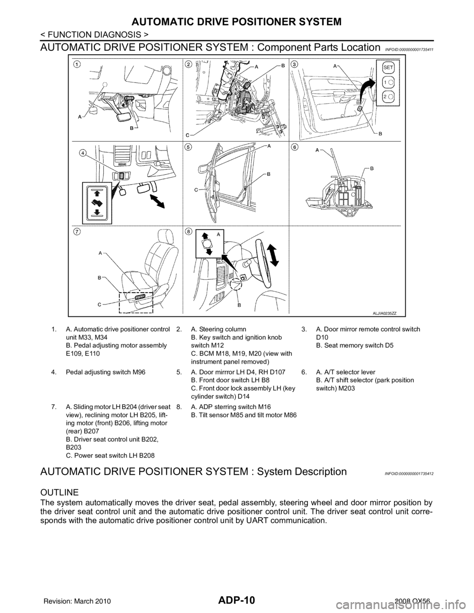
AUTOMATIC DRIVE POSITIONER SYSTEM : Component Parts Location
INFOID:0000000001735411
AUTOMATIC DRIVE POSITIONER SYSTEM : System DescriptionINFOID:0000000001735412
OUTLINE
The system automatically moves the driver seat, pedal assembly, steering wheel and door mirror position by
the driver seat control unit and the automatic drive posit ioner control unit. The driver seat control unit corre-
sponds with the automatic drive positioner control unit by UART communication.
ALJIA0235ZZ
1. A. Automatic drive positioner control
unit M33, M34
B. Pedal adjusting motor assembly
E109, E110 2. A. Steering column
B. Key switch and ignition knob
switch M12
C. BCM M18, M19, M20 (view with
instrument panel removed) 3. A. Door mirror remo
te control switch
D10
B. Seat memory switch D5
4. Pedal adjusting switch M96 5 . A. Door mirrror LH D4, RH D107
B. Front door switch LH B8
C. Front door lock assembly LH (key
cylinder switch) D14 6. A. A/T selector lever
B. A/T shift selector (park position
switch) M203
7. A. Sliding motor LH B204 (driver seat
view), reclining motor LH B205, lift-
ing motor (front) B206, lifting motor
(rear) B207
B. Driver seat control unit B202,
B203
C. Power seat switch LH B208 8. A. ADP sterring switch M16
B. Tilt sensor M85 and tilt motor M86
Revision: March 2010 2008 QX56
Page 25 of 4083

AUTOMATIC DRIVE POSITIONER SYSTEMADP-11
< FUNCTION DIAGNOSIS >
C
DE
F
G H
I
K L
M A
B
ADP
N
O P
AUTOMATIC DRIVE POSITIONER SYSTEM : Component DescriptionINFOID:0000000001735413
CONTROL UNITS
INPUT PARTS
Switches
Function Description
Manual function The driving position (seat, pedal assembly, steering wheel and door mirror position)
can be adjusted by using the power seat switch, pedal adjusting switch, ADP steering
switch or door mirror remote control switch.
Memory function The seat, pedal assembly and outside mirror move to the stored driving position by
pressing seat memory switch (1 or 2).
Entry/Exit assist function Exit On exit, the seat moves backward and the steering wheel moves upward.
Entry
On entry, the seat and steering wheel return from exiting position to the previous driv-
ing position.
Item
Function
Driver seat control unit • Main unit of automatic drive positioner system
• It is connected to the CAN.
• It communicates with the automatic drive positioner control unit via UART com-
munication.
Automatic drive positioner control unit • It communicates with the driver seat control unit via UART communication.
• Perform various controls with the instructions of driver seat control unit.
• Perform the controls of the pedal adjusting, steering wheel, door mirror and the
seat memory switch.
BCM Transmit the following status to the driver seat control unit via CAN communication.
• Front door LH: OPEN/CLOSE
• Ignition switch position: ACC/ON
• Door lock: UNLOCK (with Intelligent Key or remote keyless entry request switch
operation)
• Key ID
• Key switch: Insert/Pull out Intelligent Key
• Starter: CRANKING/OTHER
Combination meter Transmit the vehicle speed signal to the driver seat control unit via CAN communi-
cation.
AV control unit The setting change of auto drive positioner system can be performed on the display.
A/T shift selector (park position switch) Transmit the shift position signal (P range) to the driver seat control unit.
Item Function
Key switch and ignition knob switch The key switch is installed to detect the key inserted/removed status.
Front door switch LH Detect front door (driver side) open/close status.
A/T shift selector (park position switch) Detect the P range position of A/T selector lever.
Set switch The registration and system setting can be performed with its operation.
Seat memory switch 1/2 The registration and operation can be performed with its operation.
Power seat switch The following switch is installed.
• Reclining switch
• Lifting switch (front)
• Lifting switch (rear)
• Sliding switch
The specific parts can be operated with the operation of each switch.
Pedal adjusting switch The following switch is installed.
• Pedal forward
• Pedal backward
The specific parts can be operated with the operation of each switch.
Revision: March 2010
2008 QX56
Page 27 of 4083

AUTOMATIC DRIVE POSITIONER SYSTEMADP-13
< FUNCTION DIAGNOSIS >
C
DE
F
G H
I
K L
M A
B
ADP
N
O P
MANUAL FUNCTION : System DiagramINFOID:0000000001735414
MANUAL FUNCTION : System DescriptionINFOID:0000000001735415
OUTLINE
The driving position (seat, pedal assembly, steering wheel and door mirror position) can be adjusted manually
with power seat switch, pedal adjusting switch, ADP st eering switch and door mirror remote control switch.
OPERATION PROCEDURE
1. Turn ignition switch ON.
2. Operate power seat switch, pedal adjusting switch, ADP steering switch or door mirror remote control
switch.
3. The driver seat, pedal assembly, steering wheel or door mirror operates according to the operation of each switch.
DETAIL FLOW
Seat
Adjustable pedals
ALJIA0236GB
Order Input Output Control unit condition
1 Power seat switch
(sliding, lifting, reclin-
ing)
—
The power seat switch signal is inputted to the driver seat control
unit when the power seat switch is operated.
2— Motors
(sliding, lifting, reclin-
ing)The driver seat control unit outputs signals to each motor accord-
ing to the power seat switch input signal.
Revision: March 2010
2008 QX56
Page 28 of 4083

ADP-14
< FUNCTION DIAGNOSIS >
AUTOMATIC DRIVE POSITIONER SYSTEM
Tilt steering wheel
Door Mirror
NOTE:
The door mirrors can be operated manually when ignition switch is in either ACC or ON position. The ignition
switch signal (ACC/ON) is transmitted from BCM to the driver seat control unit via CAN communication and
from the driver seat control unit to the automatic drive positioner control unit via UART communication.
OrderInput Output Control unit condition
1 Pedal adjusting switch —The pedal adjusting switch signal is input to the automatic drive
positioner control unit when the pedal adjusting switch is operat-
ed.
2—M oto r The automatic drive positioner control unit actuates the motor ac-
cording to the operation of the pedal adjusting switch signal from
the driver seat control unit.
3 Sensor
(forward, backward) —The automatic drive positioner control unit recognizes any oper-
ation limit of each actuator via each sensor and will not operate
the actuator anymore at that time.
Order
Input Output Control unit condition
1 ADP steering switch —The ADP steering switch signal is input to the automatic drive po-
sitioner control unit when the ADP steering switch is operated.
2—M oto r The automatic drive positioner control unit actuates the tilt motor
according to the operation of the ADP steering switch signal.
3 Sensor
(upward, downward) —The automatic drive positioner control unit recognizes any oper-
ation limit of each actuator via each sensor and will not operate
the actuator anymore at that time.
Order
Input Output Control unit condition
1 Door mirror remote
control switch —The door mirror remote control switch signal is inputted to the au-
tomatic drive positioner control unit when the door mirror remote
control switch is operated.
2— Motors
(Door mirror motor)The automatic drive positioner control unit actuates each motor
according to the operation of the door mirror remote control switch.
Revision: March 2010
2008 QX56
Page 29 of 4083

AUTOMATIC DRIVE POSITIONER SYSTEMADP-15
< FUNCTION DIAGNOSIS >
C
DE
F
G H
I
K L
M A
B
ADP
N
O P
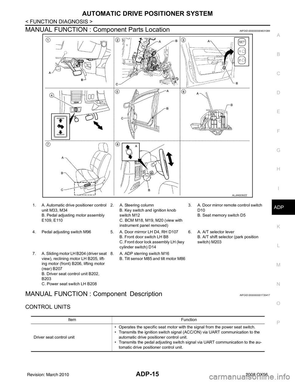
MANUAL FUNCTION : Component Parts LocationINFOID:0000000004831089
MANUAL FUNCTION : Component DescriptionINFOID:0000000001735417
CONTROL UNITS
ALJIA0235ZZ
1. A. Automatic drive positioner control unit M33, M34
B. Pedal adjusting motor assembly
E109, E110 2. A. Steering column
B. Key switch and ignition knob
switch M12
C. BCM M18, M19, M20 (view with
instrument panel removed) 3. A. Door mirror remo
te control switch
D10
B. Seat memory switch D5
4. Pedal adjusting switch M96 5 . A. Door mirrror LH D4, RH D107
B. Front door switch LH B8
C. Front door lock assembly LH (key
cylinder switch) D14 6. A. A/T selector lever
B. A/T shift selector (park position
switch) M203
7. A. Sliding motor LH B204 (driver seat view), reclining motor LH B205, lift-
ing motor (front) B2 06, lifting motor
(rear) B207
B. Driver seat control unit B202,
B203
C. Power seat switch LH B208 8. A. ADP sterring switch M16
B. Tilt sensor M85 and tilt motor M86
Item Function
Driver seat control unit • Operates the specific seat motor with the signal from the power seat switch.
• Transmits the ignition switch signal (ACC/ON) via UART communication to the
automatic drive positioner control unit.
• Transmits the pedal adjusting switch signal via UART communication to the au- tomatic drive positioner control unit.
Revision: March 2010 2008 QX56
Page 30 of 4083

ADP-16
< FUNCTION DIAGNOSIS >
AUTOMATIC DRIVE POSITIONER SYSTEM
INPUT PARTS
Switches
Sensors
OUTPUT PARTS
MEMORY FUNCTION
Automatic drive positioner control unitOperates the specific motor with the signal from driver seat control unit, ADP steer-
ing switch or door mirror remote control switch.
BCM Recognizes the following status and transmits it to the driver seat control unit via
CAN communication.
• Ignition position: ACC/ON
Item
Function
Item Function
Power seat switch The following switch is installed.
• Reclining switch
• Lifting switch (front)
• Lifting switch (rear)
• Sliding switch
The specific parts can be operated with the operation of each switch.
Pedal adjusting switch The following switch is installed.
• Pedal forward
• Pedal backward
The specific parts can be operated with the operation of each switch.
ADP steering switch The following switch is installed.
• Steering wheel upward
• Steering wheel downward
The specific parts can be operated with the operation of each switch.
Door mirror remote control switch The following switch is installed.
• Mirror switch
• Changeover switch
The specific parts can be operated with the operation of each switch.
Item
Function
Pedal adjusting sensor Detect the forward/backward position of pedal assembly.
Tilt sensor Detect the upward/downward position of steering wheel.
Item Function
Door mirror motor (LH/RH) Move the outside mirror face upward/downward and leftward/rightward.
Pedal adjusting motor Move the pedal assembly forward/backward.
Tilt motor Move the steering wheel upward/downward.
Lifting motor (front) Move the seat lifter (front) upward/downward.
Lifting motor (rear) Move the seat lifter (rear) upward/downward.
Reclining motor Tilt and raise up the seatback.
Sliding motor Slide the seat forward/backward.
Revision: March 2010 2008 QX56
Page 31 of 4083

AUTOMATIC DRIVE POSITIONER SYSTEMADP-17
< FUNCTION DIAGNOSIS >
C
DE
F
G H
I
K L
M A
B
ADP
N
O P
MEMORY FUNCTION : System DiagramINFOID:0000000001735418
MEMORY FUNCTION : System DescriptionINFOID:0000000001735419
OUTLINE
The driver seat control unit can store the optimum driving positions (seat, pedal assembly, steering wheel and
door mirror position) for 2 people. If the front seat position is changed, one-touch (pressing desired memory
switch for more than 0.5 second) operation al lows changing to the other driving position.
NOTE:
Further information for the memory storage procedure. Refer to Owner’s Manual.
OPERATION PROCEDURE
1. Turn ignition switch ON
2. Press desired memory switch for more than 0.5 second.
3. Front seat LH, pedal assembly, steering wheel and door mirror will move to the memorized position.
OPERATION CONDITION
Satisfy all of the following items. The memory func tion is not performed if these items are not satisfied.
DETAIL FLOW
ALJIA0237GB
Item Request status
Ignition position ON
Switch inputs
• Power seat switch
• Pedal adjusting switch
• ADP steering switch
• Door mirror control switch
• Set switch
• Seat memory switch OFF
(Not operated)
A/T selector lever P position
Revision: March 2010 2008 QX56