torque INFINITI QX56 2008 Factory Manual Online
[x] Cancel search | Manufacturer: INFINITI, Model Year: 2008, Model line: QX56, Model: INFINITI QX56 2008Pages: 4083, PDF Size: 81.73 MB
Page 1855 of 4083
EM-52
< ON-VEHICLE REPAIR >
TIMING CHAIN
a. Apply engine oil onto the threaded parts of the bolt and seating area.
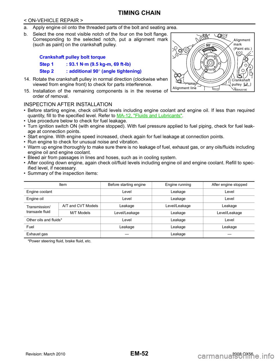
b. Select the one most visible notch of the four on the bolt flange.Corresponding to the selected notch, put a alignment mark
(such as paint) on the crankshaft pulley.
14. Rotate the crankshaft pulley in normal direction (clockwise when viewed from engine front) to check for parts interference.
15. Installation of the remaining components is in the reverse of order of removal.
INSPECTION AFTER INSTALLATION
• Before starting engine, check oil/fluid levels incl uding engine coolant and engine oil. If less than required
quantity, fill to the specified level. Refer to MA-12, "
Fluids and Lubricants".
• Use procedure below to check for fuel leakage.
• Turn ignition switch ON (with engine stopped). With fuel pressure applied to fuel piping, check for fuel leak- age at connection points.
• Start engine. With engine speed increased, che ck again for fuel leakage at connection points.
• Run engine to check for unusual noise and vibration.
• Warm up engine thoroughly to make sure there is no leakage of fuel, exhaust gas, or any oils/fluids including
engine oil and engine coolant.
• Bleed air from passages in lines and hoses, such as in cooling system.
• After cooling down engine, again check oil/fluid levels including engine oil and engine coolant. Refill to spec-
ified level, if necessary.
• Summary of the inspection items:
*Power steering fluid, brake fluid, etc.
Crankshaft pulley bolt torque
Step 1 : 93.1 N·m (9.5 kg-m, 69 ft-lb)
Step 2 : additional 90 ° (angle tightening)
KBIA2519E
Item Before starting engine Engine runningAfter engine stopped
Engine coolant LevelLeakage Level
Engine oil LevelLeakage Level
Transmission/
transaxle fluid A/T and CVT Models
LeakageLevel/Leakage Leakage
M/T Models Level/Leakage LeakageLevel/Leakage
Other oils and fluids* LevelLeakage Level
Fuel LeakageLeakage Leakage
Exhaust gas —Leakage —
Revision: March 2010 2008 QX56
Page 1860 of 4083
CAMSHAFTEM-57
< ON-VEHICLE REPAIR >
C
DE
F
G H
I
J
K L
M A
EM
NP
O
11. Remove the camshaft.
12. Remove the valve lifters if necessary.
• Correctly identify location where each part is removed from. Keep parts organized to avoid mixing them
up.
INSPECTION AFTER REMOVAL
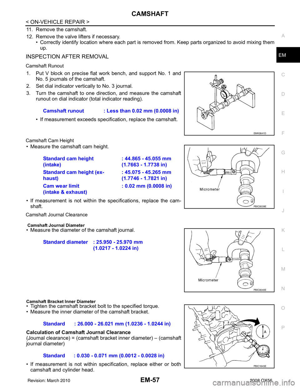
Camshaft Runout
1. Put V block on precise flat work bench, and support No. 1 and No. 5 journals of the camshaft.
2. Set dial indicator vertically to No. 3 journal.
3. Turn the camshaft to one direction, and measure the camshaft runout on dial indicator (total indicator reading).
• If measurement exceeds specif ication, replace the camshaft.
Camshaft Cam Height
• Measure the camshaft cam height.
• If measurement is not within the specifications, replace the cam-
shaft.
Camshaft Journal Clearance
Camshaft Journal Diameter
• Measure the diameter of the camshaft journal.
Camshaft Bracket Inner Diameter
• Tighten the camshaft bracket bolt to the specified torque.
• Measure the inner diameter of the camshaft bracket.
Calculation of Camshaft Journal Clearance
(Journal clearance) = (camshaft bracket inner diameter) – (camshaft
journal diameter)
• If measurement is not within specification, replace either or both
camshaft and cylinder head. Camshaft runout : Less than 0.02 mm (0.0008 in)
EMK0641D
Standard cam height
(intake)
: 44.865 - 45.055 mm
(1.7663 - 1.7738 in)
Standard cam height (ex-
haust) : 45.075 - 45.265 mm
(1.7746 - 1.7821 in)
Cam wear limit
(intake & exhaust) : 0.02 mm (0.0008 in)
PBIC0039E
Standard diameter : 25.950 - 25.970 mm
(1.0217 - 1.0224 in)
PBIC0040E
Standard : 26.000 - 26.021 mm (1.0236 - 1.0244 in)
Standard : 0.030 - 0.071 mm (0.0012 - 0.0028 in)
PBIC1645E
Revision: March 2010 2008 QX56
Page 1864 of 4083

CAMSHAFTEM-61
< ON-VEHICLE REPAIR >
C
DE
F
G H
I
J
K L
M A
EM
NP
O
- Position No. 1 camshaft bracket close to the mounting posi-
tion, and then install it to prevent from touching liquid gasket
applied to each surface.
- Temporarily tighten the RH (A) and LH (B) front cover bolts (4 for each bank) as shown.
4. Tighten the camshaft bracket bolts as follows: CAUTION:
After tightening the camshaft br acket bolts, be sure to wipe
off excessive liquid gasket from the parts listed below.
• Mating surface of rocker cover
• Mating surface of front cover
• A: RH bank
• B: Exhaust side
• C: LH bank
• D: Intake side
a. Tighten the RH (A) and LH (B) front cover bolts (4 for each bank) as shown to the specified torque.
SBIA0259E
WBIA0706E
Camshaft bracket bolts
Step 1 (bolts 9 - 12) : 2.0 N·m (0.2 kg-m, 17 in-lb)
Step 2 (bolts 1 - 8) : 2.0 N·m (0.2 kg-m, 17 in-lb)
Step 3 (all bolts) : 5.9 N·m (0.6 kg-m, 52 in-lb)
Step 4 (all bolts) : 10.4 N·m (1.1 kg-m, 92 in-lb)
WBIA0707E
Front cover bolts : 11.0 N·m (1.1 kg-m, 8 ft-lb)
WBIA0706E
Revision: March 2010 2008 QX56
Page 1869 of 4083
EM-66
< ON-VEHICLE REPAIR >
OIL SEAL
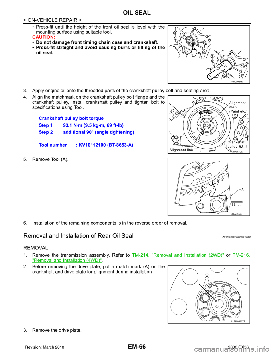
• Press-fit until the height of the front oil seal is level with themounting surface using suitable tool.
CAUTION:
• Do not damage front timing chain case and crankshaft.
• Press-fit straight and avoid cau sing burrs or tilting of the
oil seal.
3. Apply engine oil onto the threaded parts of the crankshaft pulley bolt and seating area.
4. Align the matchmark on the crankshaft pulley bolt flange and the crankshaft pulley, install crankshaft pulley and tighten bolt to
specifications using Tool.
5. Remove Tool (A).
6. Installation of the remaining components is in the reverse order of removal.
Removal and Installation of Rear Oil SealINFOID:0000000004975988
REMOVAL
1. Remove the transmission assembly. Refer to TM-214, "Removal and Installation (2WD)" or TM-216,
"Removal and Installation (4WD)".
2. Before removing the drive plate, put a match mark (A) on the crankshaft and drive plate for alignment during installation
3. Remove the drive plate.
PBIC2931E
Crankshaft pulley bolt torque
Step 1 : 93.1 N·m (9.5 kg-m, 69 ft-lb)
Step 2 : additional 90 ° (angle tightening)
Tool number : KV10112100 (BT-8653-A)
KBIA2519E
LBIA0455E
ALBIA0522ZZ
Revision: March 2010 2008 QX56
Page 1882 of 4083
ENGINE ASSEMBLYEM-79
< REMOVAL AND INSTALLATION >
C
DE
F
G H
I
J
K L
M A
EM
NP
O
4. Remove the engine hood. Refer to
DLK-224, "Removal and Installation of Hood Assembly".
5. Remove the cowl extension. Refer to EXT-18, "
Removal and Installation".
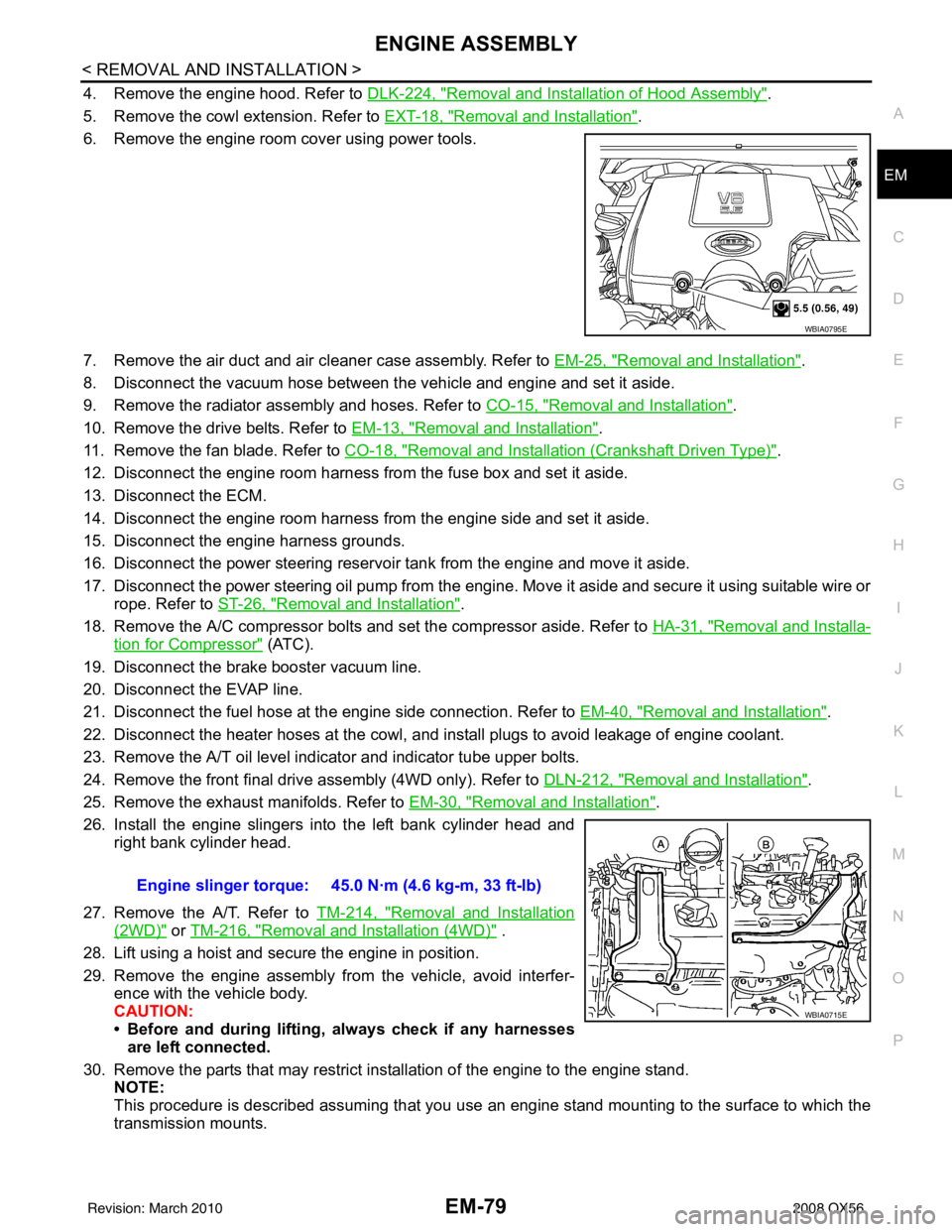
6. Remove the engine room cover using power tools.
7. Remove the air duct and air cleaner case assembly. Refer to EM-25, "
Removal and Installation".
8. Disconnect the vacuum hose between the vehicle and engine and set it aside.
9. Remove the radiator assembly and hoses. Refer to CO-15, "
Removal and Installation".
10. Remove the drive belts. Refer to EM-13, "
Removal and Installation".
11. Remove the fan blade. Refer to CO-18, "
Removal and Installation (Crankshaft Driven Type)".
12. Disconnect the engine room harness from the fuse box and set it aside.
13. Disconnect the ECM.
14. Disconnect the engine room harness from the engine side and set it aside.
15. Disconnect the engine harness grounds.
16. Disconnect the power steering reservoir t ank from the engine and move it aside.
17. Disconnect the power steering oil pump from the engine. Move it aside and secure it using suitable wire or rope. Refer to ST-26, "
Removal and Installation".
18. Remove the A/C compressor bolts and set the compressor aside. Refer to HA-31, "
Removal and Installa-
tion for Compressor" (ATC).
19. Disconnect the brake booster vacuum line.
20. Disconnect the EVAP line.
21. Disconnect the fuel hose at the engine side connection. Refer to EM-40, "
Removal and Installation".
22. Disconnect the heater hoses at the cowl, and in stall plugs to avoid leakage of engine coolant.
23. Remove the A/T oil level indicator and indicator tube upper bolts.
24. Remove the front final drive assembly (4WD only). Refer to DLN-212, "
Removal and Installation".
25. Remove the exhaust manifolds. Refer to EM-30, "
Removal and Installation".
26. Install the engine slingers into the left bank cylinder head and right bank cylinder head.
27. Remove the A/T. Refer to TM-214, "
Removal and Installation
(2WD)" or TM-216, "Removal and Installation (4WD)" .
28. Lift using a hoist and secure the engine in position.
29. Remove the engine assembly from the vehicle, avoid interfer- ence with the vehicle body.
CAUTION:
• Before and during lifting, always check if any harnessesare left connected.
30. Remove the parts that may restrict installation of the engine to the engine stand. NOTE:
This procedure is described assuming that you use an engine stand mounting to the surface to which the
transmission mounts.
WBIA0795E
Engine slinger torque: 45.0 N·m (4.6 kg-m, 33 ft-lb)
WBIA0715E
Revision: March 2010 2008 QX56
Page 1889 of 4083

EM-86
< DISASSEMBLY AND ASSEMBLY >
ENGINE UNIT
ASSEMBLY
1. Fully air-blow the coolant and oil passages in the cylinder block, cylinder bore, and crankcase to removeany foreign material.
CAUTION:
Use goggles to protect your eyes.
2. Install each plug to the cylinder block (only screw-type plugs are shown).
• Apply liquid gasket. Use Genuine Thread Sealant or equivalent. Refer to GI-15,
"Recommended Chemical Products and Sealants".
• Replace copper washers with new ones.
• Tighten each plug as specified below.
3. Install main bearings and thrust bearings.
a. Remove any dust, dirt, and oil on the bearing mating surfaces of the cylinder block and main bearing caps.
b. Install thrust bearings to both sides of the No. 3 journal housing on the cylinder block and main bearing caps
• Install thrust bearings with the oil groove facing the crankshaft
arm (outside).
• Install thrust bearings with a protrusion in the center on the
main bearing caps.
c. Install main bearings paying attention to the direction. • Install the one with oil holes onto the cylinder block and theone without oil holes onto the main bearing cap.
• Before installing bearings, apply engine oil to bearing surface
(inside). Do not apply oil to the back surface, but thoroughly
clean it.
• When installing, align the bearing stopper to the notch.
• Ensure the oil holes on the cylinder block and those on the
corresponding bearing are aligned.
4. Install pilot converter to the crankshaft using suitable tool.
5. Install crankshaft to the cylinder block. • While turning crankshaft by hand, make sure it turns smoothly.
Part Washer Tightening torque
A Yes 53.9 N·m (5.5 kg-m, 40 ft-lb)
B No 19.6 N·m (2.0 kg-m, 15 ft-lb)
C Yes 62.7 N·m (6.4 kg-m, 46 ft-lb)
D Yes 62.7 N·m (6.4 kg-m, 46 ft-lb)
WBIA0419E
PBIC0093E
PBIC0094E
EMP0569D
Revision: March 2010 2008 QX56
Page 1896 of 4083

ENGINE UNITEM-93
< DISASSEMBLY AND ASSEMBLY >
C
DE
F
G H
I
J
K L
M A
EM
NP
O
CONNECTING ROD BEND AND TORSION
• Check connecting rod alignment using suitable tool.
• If measurement exceeds the limi
t, replace connecting rod assem-
bly.
CONNECTING ROD BEARING (BIG END)
• Install the connecting rod cap without the connecting rod bearing installed. After tightening the connecting rod bolt to the specified
torque, measure the connecting rod large end inside diameter.
Refer to EM-82, "
Disassembly and Assembly".
• If measurement exceeds the standard, replace connecting rod.
CONNECTING ROD BUSHING OIL CLEARANCE (SMALL END)
Connecting Rod Inside Diameter (Small End)
• Measure inside diameter of bushing using suitable tool.
Piston Pin Diameter
Limit: Bend: 0.15 mm (0.0059 in) per 100 mm (3.94 in) length
To r s i o n : 0.30 mm (0.0118 in) per 100 mm (3.94 in) length
SEM003F
SEM038F
Standard : 57.000 - 57.013 mm (2.2441 - 2.2446 in)
PBIC1641E
Standard : 22.000 - 22.006 mm (0.8661 - 0.8664 in)
PBIC0120E
Revision: March 2010 2008 QX56
Page 1898 of 4083

ENGINE UNITEM-95
< DISASSEMBLY AND ASSEMBLY >
C
DE
F
G H
I
J
K L
M A
EM
NP
O
• Install the main bearing caps with the main bearings removed, and
tighten the bolts to the specified torque. Refer to EM-82, "
Disas-
sembly and Assembly".
• Measure inside diameter of main bearing housing.
• If out of the standard, replace cylinder block and main bearing caps as an assembly.
NOTE:
These components must be replaced as a single unit, because
they were processed together.
PISTON TO CYLINDER BORE CLEARANCE
Cylinder Bore Diameter
• Measure the cylinder bore for wear, out-of-round and taper at six
different points on each cylinder ( ″X″ and ″Y″ directions at ″A″ , ″B″
and ″C ″).
NOTE:
When determining cylinder bore grade, measure cylinder bore at
"B" position.
• If measured value exceeds the repair limit, or if ther e are scratches and/or seizure on the cylinder inner wall,
hone or bore the inner wall.
Piston Skirt Diameter
• Measure piston skirt diameter using suitable tool. Standard : 68.944 - 68.968 mm (2.7143 - 2.7153 in)
PBIC1643E
PBIC0123E
Standard diameter:
98.000 - 98.030 mm (3.8583 - 3.8594 in)
Wear limit: 0.20 mm (0.0079 in)
Out-of-round (Difference between ″X″ and ″Y″ ):
Limit: 0.015 mm (0.0006 in)
Taper limit (Difference between ″A ″ and ″C ″):
Limit: 0.010 mm (0.0004 in)
PBIC0124E
Standard : 97. 980 - 98. 010 mm (3.8575 - 3.8587 in)
PBIC0125E
Revision: March 2010 2008 QX56
Page 1899 of 4083

EM-96
< DISASSEMBLY AND ASSEMBLY >
ENGINE UNIT
• Measure point ″H″.
Piston to Cylinde r Bore Clearance
• Calculate by using diameter of the piston skirt and the cylinder bore diameter (direction X, position B).
(Clearance) = (Cylinder bore diameter) – (piston skirt diameter)
• If calculation exceeds the limit, replace piston/piston pin assembly.
Reboring Cylinder Bore
1. Cylinder bore size is determined by adding pi ston-to-bore clearance to piston diameter “A”.
2. Install main bearing caps, and tighten them to the specified torque. Otherwise, cylinder bores may be dis-
torted in final assembly.
3. Cut the cylinder bores. NOTE:
• When any cylinder needs boring, all other cylinders must also be bored.
• Do not cut too much out of cylinder bore at one time. Cut only 0.05 mm (0.0020 in) or so in diameter at atime.
4. Hone cylinders to obtain the specified piston-to-bore clearance.
5. Measure finished cylinder bore for out-of-round and taper. NOTE:
Measurement should be done after cylinder bore cools down.
CRANKSHAFT JOURNAL DIAMETER
• Measure diameter of crankshaft journals.
• If measurement is out of standard, measure the ma in bearing oil clearance. Then use the undersize bearing.
Follow the "MAIN BEARING OIL CLEARANCE" procedure.
CRANKSHAFT PIN DIAMETER
Distance from the top : 39 mm (1.54 in)
KBIA2545E
Standard : 0.010 - 0.030 mm (0.0004 - 0.0012 in)
Limit : 0.08 mm (0.0031 in)
Rebored size calculation: D = A +B - C
where,
D: Bored diameter
A: Piston diameter as measured
B: Piston - to - bore clearance (standard value)
C: Honing allowance 0.02 mm (0.0008 in)
Standard : 63.940 - 63.964 mm (2.5173 - 2.5183 in)
Revision: March 2010 2008 QX56
Page 1900 of 4083
ENGINE UNITEM-97
< DISASSEMBLY AND ASSEMBLY >
C
DE
F
G H
I
J
K L
M A
EM
NP
O
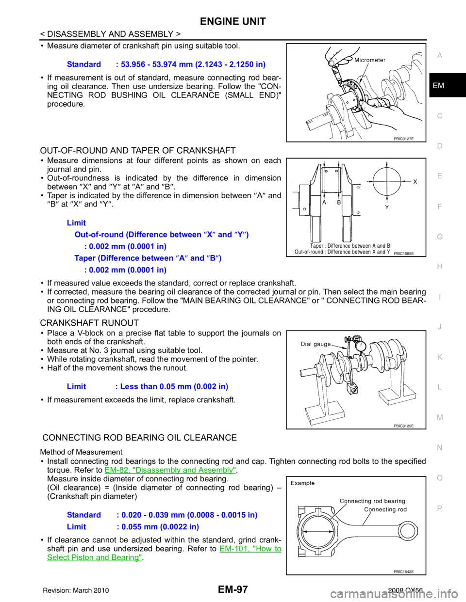
• Measure diameter of crankshaft pin using suitable tool.
• If measurement is out of standard, measure connecting rod bear-
ing oil clearance. Then use undersize bearing. Follow the "CON-
NECTING ROD BUSHING OIL CLEARANCE (SMALL END)"
procedure.
OUT-OF-ROUND AND TAPER OF CRANKSHAFT
• Measure dimensions at four di fferent points as shown on each
journal and pin.
• Out-of-roundness is indicated by the difference in dimension
between ″X″ and ″Y″ at ″A″ and ″B″ .
• Taper is indicated by the difference in dimension between ″A ″ and
″ B″ at ″X ″ and ″Y″ .
• If measured value exceeds the standard, correct or replace crankshaft.
• If corrected, measure the bearing oil clearance of the corrected journal or pin. Then select the main bearing or connecting rod bearing. Follow the "MAIN BEA RING OIL CLEARANCE" or " CONNECTING ROD BEAR-
ING OIL CLEARANCE" procedure.
CRANKSHAFT RUNOUT
• Place a V-block on a precise flat table to support the journals on both ends of the crankshaft.
• Measure at No. 3 journal using suitable tool.
• While rotating crankshaft, read the movement of the pointer.
• Half of the movement shows the runout.
• If measurement exceeds the limit, replace crankshaft.
CONNECTING ROD BEARING OIL CLEARANCE
Method of Measurement
• Install connecting rod bearings to the connecting rod and cap. Tighten connecting rod bolts to the specified
torque. Refer to EM-82, "
Disassembly and Assembly".
Measure inside diameter of connecting rod bearing.
(Oil clearance) = (Inside diameter of connecting rod bearing) –
(Crankshaft pin diameter)
• If clearance cannot be adjusted wit hin the standard, grind crank-
shaft pin and use undersized bearing. Refer to EM-101, "
How to
Select Piston and Bearing".
Standard : 53.956 - 53.974 mm (2.1243 - 2.1250 in)
PBIC0127E
Limit
Out-of-round (Difference between ″X ″ and ″ Y″)
: 0.002 mm (0.0001 in)
Taper (Difference between ″ A″ and ″B ″)
: 0.002 mm (0.0001 in)
PBIC1685E
Limit : Less than 0.05 mm (0.002 in)
PBIC0129E
Standard : 0.020 - 0.039 mm (0.0008 - 0.0015 in)
Limit : 0.055 mm (0.0022 in)
PBIC1642E
Revision: March 2010 2008 QX56