Fax INFINITI QX56 2008 Factory Service Manual
[x] Cancel search | Manufacturer: INFINITI, Model Year: 2008, Model line: QX56, Model: INFINITI QX56 2008Pages: 4083, PDF Size: 81.73 MB
Page 1 of 4083
A
B
C
D
E
F
G
H
I
J
K
L
M
N
P
O
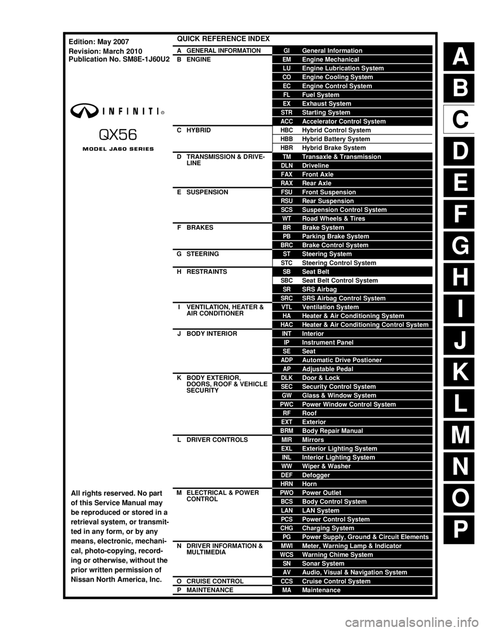
QUICK REFERENCE INDEX
AGENERAL INFORMATIONGIGeneral Information
BENGINEEMEngine Mechanical
LUEngine Lubrication System
COEngine Cooling System
ECEngine Control System
FLFuel System
EXExhaust System
STRStarting System
ACCAccelerator Control System
CHYBRIDHBCHybrid Control System
HBBHybrid Battery System
HBRHybrid Brake System
DTRANSMISSION & DRIVE-
LINETMTransaxle & Transmission
DLNDriveline
FAXFront Axle
RAXRear Axle
ESUSPENSIONFSUFront Suspension
RSURear Suspension
SCSSuspension Control System
WTRoad Wheels & Tires
FBRAKESBRBrake System
PBParking Brake System
BRCBrake Control System
GSTEERINGSTSteering System
STCSteering Control System
HRESTRAINTSSBSeat Belt
SBCSeat Belt Control System
SRSRS Airbag
SRCSRS Airbag Control System
IVENTILATION, HEATER &
AIR CONDITIONERVTLVentilation System
HAHeater & Air Conditioning System
HACHeater & Air Conditioning Control System
JBODY INTERIORINTInterior
IPInstrument Panel
SESeat
ADPAutomatic Drive Postioner
APAdjustable Pedal
KBODY EXTERIOR,
DOORS, ROOF & VEHICLE
SECURITYDLKDoor & Lock
SECSecurity Control System
GWGlass & Window System
PWCPower Window Control System
RFRoof
EXTExterior
BRMBody Repair Manual
LDRIVER CONTROLSMIRMirrors
EXLExterior Lighting System
INLInterior Lighting System
WWWiper & Washer
DEFDefogger
HRNHorn
MELECTRICAL & POWER
CONTROLPWOPower Outlet
BCSBody Control System
LANLAN System
PCSPower Control System
CHGCharging System
PGPower Supply, Ground & Circuit Elements
NDRIVER INFORMATION &
MULTIMEDIAMWIMeter, Warning Lamp & Indicator
WCSWarning Chime System
SNSonar System
AVAudio, Visual & Navigation System
OCRUISE CONTROLCCSCruise Control System
PMAINTENANCEMAMaintenance
All rights reserved. No part
of this Service Manual may
be reproduced or stored in a
retrieval system, or transmit-
ted in any form, or by any
means, electronic, mechani-
cal, photo-copying, record-
ing or otherwise, without the
prior written permission of
Nissan North America, Inc.
Edition: May 2007
Revision: March 2010
Publication No. SM8E-1J60U2
Page 3 of 4083

PLEASEHELPMAKETHISSERVICEMANUALBETTER!
YourcommentsareimportanttoINFINITIandwillhelpustoimproveourServiceManuals.
UsethisformtoreportanyissuesorcommentsyoumayhaveregardingourServiceManuals.
Pleaseprintthisformandtypeorwriteyourcommentsbelow.Mailorfaxto:
NissanNorthAmerica,Inc.
TechnicalServiceInformation
39001SunriseDrive,P.O.Box9200
FarmingtonHills,MIUSA48331
FAX:(248)488-3910
SERVICEMANUAL:Model:Year:
PUBLICATIONNO.(Refer to Quick Reference Index ):
Pleasedescribeany Service Manualissuesorproblemsindetail:
Pagenumber(s)Note:Pleaseincludeacopyofeachpage,markedwithyourcomments.
Arethetroublediagnosisprocedureslogicalandeasytouse?(circleyouranswer)YESNO
Ifno,whatpagenumber(s)?Note:Pleaseincludeacopyofeachpage,markedwithyourcomments.
Pleasedescribetheissueorproblemindetail:
Istheorganizationofthemanualclearandeasytofollow?(circleyouranswer)YESNO
Pleasecomment:
WhatinformationshouldbeincludedinINFINITIServiceManualstobettersupportyouinservicingor
repairingcustomervehicles?
DATE:YOURNAME:POSITION:
DEALER:DEALERNO.:ADDRESS:
CITY:STATE/PROV./COUNTRY:ZIP/POSTALCODE:
RINFINITI
Page 426 of 4083

BR-6
< FUNCTION DIAGNOSIS >
NOISE, VIBRATION AND HARSHNESS (NVH) TROUBLESHOOTING
FUNCTION DIAGNOSIS
NOISE, VIBRATION AND HARSHNESS (NVH) TROUBLESHOOTING
NVH Troubleshooting ChartINFOID:0000000004894481
Use the chart below to help you find the cause of the sy mptom. If necessary, repair or replace these parts.
×: ApplicableReference page
BR-7
, BR-9
BR-7
, BR-9
BR-7
, BR-9
BR-7
, BR-9
BR-7
, BR-9
BR-7
, BR-9
BR-7
, BR-9
BR-7
, BR-9
BR-7
, BR-9
BR-7
, BR-9
DLN-182, "
NVH Troubleshooting Chart
" (2F1310),
DLN-192, "
NVH Troubleshooting Chart
" (2S1410)
DLN-206, "
NVH Troubleshooting Chart
" (FFD),
DLN-240, "
NVH Troubleshooting Chart
" (RFD)
FAX-5, "
NVH Troubleshooting Chart
" (FAX),
RAX-5, "
NVH Troubleshooting Chart
" (RAX)
FSU-6, "
NVH Troubleshooting Chart
" (FSU),
RSU-5, "
NVH Troubleshooting Chart
" (RSU)
WT-41, "
NVH Troubleshooting Chart
"
ST-12, "
NVH Troubleshooting Chart
"
Possible cause and
SUSPECTED PARTS
Pads - damaged
Pads - uneven wear
Shims damaged
Rotor imbalance
Rotor damage
Rotor runout
Rotor deformation
Rotor deflection
Rotor rust
Rotor thickness variation
PROPELLER SHAFT
DIFFERENTIAL
DRIVESHAFT
SUSPENSION
TIRES AND ROAD WHEEL
STEERING
Symptom Noise
××× × × × × ××
Shake ×× ××××
Shimmy, Shudder ××××××× × × ××
Revision: March 2010 2008 QX56
Page 497 of 4083
![INFINITI QX56 2008 Factory Service Manual BRC-30
< COMPONENT DIAGNOSIS >[VDC/TCS/ABS]
C1101, C1102, C1103,
C1104 WHEEL SENSOR-1
3. Spin the wheel of the vehicle by hand and observe the red SENSOR indicator on the ABS active wheel
sensor tes](/img/42/57030/w960_57030-496.png "INFINITI QX56 2008 Factory Service Manual BRC-30
< COMPONENT DIAGNOSIS >[VDC/TCS/ABS]
C1101, C1102, C1103,
C1104 WHEEL SENSOR-1
3. Spin the wheel of the vehicle by hand and observe the red SENSOR indicator on the ABS active wheel
sensor tes")
BRC-30
< COMPONENT DIAGNOSIS >[VDC/TCS/ABS]
C1101, C1102, C1103,
C1104 WHEEL SENSOR-1
3. Spin the wheel of the vehicle by hand and observe the red SENSOR indicator on the ABS active wheel
sensor tester. The red SENSOR indicator should flash on and off to indicate an output signal.
NOTE:
If the red SENSOR indicator illuminates but does not flash, reverse the polarity of the tester leads and
retest.
Does the ABS active wheel sensor tester detect a signal?
YES >> GO TO 3
NO >> Replace the wheel sensor. Refer to BRC-114, "
Removal and Installation".
3.CHECK TIRES
Check for inflation pressure, wear and size of each tire.
Are tire pressure and size correct and is tire wear within specifications?
YES >> GO TO 4
NO >> Adjust tire pressure or replace tire(s).
4.CHECK WHEEL BEARINGS
Check wheel bearing axial end play. Refer to FAX-6, "
On-Vehicle Inspection and Service" (front) or RAX-6,
"On-Vehicle Inspection and Service" (rear).
Is the inspection result normal?
YES >> GO TO 5
NO >> Repair or replace as necessary. Refer to FA X - 7 , "
Removal and Installation" (front) or RAX-8,
"Removal and Installation" (rear).
5.CHECK WIRING HARNESS FOR SHORT CIRCUIT
1. Disconnect ABS actuator and elec tric unit (control unit) connec-
tor and wheel sensor connector of malfunction code No.
2. Check continuity between wheel sensor harness connector ter-
minals and ground.
Is the inspection result normal?
YES >> GO TO 6
NO >> Repair the circuit.
6.CHECK WIRING HARNESS FOR OPEN CIRCUIT
1. Check continuity between ABS actuator and electric unit (control unit) harness connector E125 and the malfunctioning wheel sensor harness c onnector E18, E117, C10, or C11.
Is the inspection result normal?
YES >> Replace the ABS actuator and electric unit (control unit). Refer to BRC-116, "Removal and Instal-
lation".
NO >> Repair the circuit. Continuity should not exist.
WFIA0343E
Wheel sensor
ABS actuator and
electric unit (control unit) Wheel sensor
Continuity
Connector Terminal Connector Terminal
Front LH
E12545
E18 1
Ye s
46
2
Front RH 34
E117 1
33 2
Rear LH 37
C11 2
36 1
Rear RH 42
C10 2
43 1
Revision: March 2010 2008 QX56
Page 500 of 4083
![INFINITI QX56 2008 Factory Service Manual C1105, C1106, C1107, C1108 WHEEL SENSOR-2
BRC-33
< COMPONENT DIAGNOSIS > [VDC/TCS/ABS]
C
D
E
G H
I
J
K L
M A
B
BRC
N
O P
2.CHECK WHEEL SENSOR OUTPUT SIGNAL
1. Connect ABS active wheel sensor tester (J](/img/42/57030/w960_57030-499.png "INFINITI QX56 2008 Factory Service Manual C1105, C1106, C1107, C1108 WHEEL SENSOR-2
BRC-33
< COMPONENT DIAGNOSIS > [VDC/TCS/ABS]
C
D
E
G H
I
J
K L
M A
B
BRC
N
O P
2.CHECK WHEEL SENSOR OUTPUT SIGNAL
1. Connect ABS active wheel sensor tester (J")
C1105, C1106, C1107, C1108 WHEEL SENSOR-2
BRC-33
< COMPONENT DIAGNOSIS > [VDC/TCS/ABS]
C
D
E
G H
I
J
K L
M A
B
BRC
N
O P
2.CHECK WHEEL SENSOR OUTPUT SIGNAL
1. Connect ABS active wheel sensor tester (J- 45741) to wheel sensor using appropriate adapter.
2. Turn on the ABS active wheel sensor tester power switch.
NOTE:
The green POWER indicator should illuminate. If the POWER indicator does not illuminate, replace the
battery in the ABS active wheel sensor tester before proceeding.
3. Spin the wheel of the vehicle by hand and observe the red SENSOR indicator on the ABS active wheel
sensor tester. The red SENSOR indicator should flash on and off to indicate an output signal.
NOTE:
If the red SENSOR indicator illuminates but does not flash, reverse the polarity of the tester leads and
retest.
Does the ABS active wheel s ensor tester detect a signal?
YES >> GO TO 3
NO >> Replace the wheel sensor. Refer to BRC-114, "
Removal and Installation".
3.CHECK TIRES
Check for inflation pressure, wear and size of each tire.
Are tire pressure and size correct and is tire wear within specifications?
YES >> GO TO 4
NO >> Adjust tire pressure or replace tire(s).
4.CHECK WHEEL BEARINGS
Check wheel bearing axial end play. Refer to FA X - 6 , "
On-Vehicle Inspection and Service" (front) or RAX-6,
"On-Vehicle Inspection and Service" (rear).
Is the inspection result normal?
YES >> GO TO 5
NO >> Repair or replace as necessary. Refer to FAX-7, "
Removal and Installation" (front) or RAX-8,
"Removal and Installation" (rear).
5.CHECK WIRING HARNESS FOR SHORT CIRCUIT
1. Disconnect ABS actuator and electric unit (control unit) connec- tor and wheel sensor connector of malfunction code No.
2. Check continuity between wheel sensor harness connector ter-
minals and ground.
Is the inspection result normal?
YES >> GO TO 6
NO >> Repair the circuit.
6.CHECK WIRING HARNESS FOR OPEN CIRCUIT
1. Check continuity between ABS actuator and electric unit (control unit) harness connector E125 and the malfunctioning wheel sensor harness connector E18, E117, C10, or C11.Continuity should not exist.
WFIA0343E
Revision: March 2010
2008 QX56
Page 511 of 4083
![INFINITI QX56 2008 Factory Service Manual BRC-44
< COMPONENT DIAGNOSIS >[VDC/TCS/ABS]
C1115 WHEEL SENSOR
Check for inflation pressure, wear and size of each tire.
Are tire pressure and size correct and is tire wear within specifications?
YES](/img/42/57030/w960_57030-510.png "INFINITI QX56 2008 Factory Service Manual BRC-44
< COMPONENT DIAGNOSIS >[VDC/TCS/ABS]
C1115 WHEEL SENSOR
Check for inflation pressure, wear and size of each tire.
Are tire pressure and size correct and is tire wear within specifications?
YES")
BRC-44
< COMPONENT DIAGNOSIS >[VDC/TCS/ABS]
C1115 WHEEL SENSOR
Check for inflation pressure, wear and size of each tire.
Are tire pressure and size correct and is tire wear within specifications?
YES >> GO TO 4
NO >> Adjust tire pressure or replace tire(s).
4.CHECK WHEEL BEARINGS
Check wheel bearing axial end play. Refer to FAX-6, "
On-Vehicle Inspection and Service" (front) or RAX-6,
"On-Vehicle Inspection and Service" (rear).
Is the inspection result normal?
YES >> GO TO 5
NO >> Repair or replace as necessary. Refer to FA X - 7 , "
Removal and Installation" (front) or RAX-8,
"Removal and Installation" (rear).
5.CHECK WIRING HARNESS FOR SHORT CIRCUIT
1. Disconnect ABS actuator and elec tric unit (control unit) connec-
tor and wheel sensor connector of malfunction code No.
2. Check continuity between wheel sensor harness connector ter-
minals and ground.
Is the inspection result normal?
YES >> GO TO 6
NO >> Repair the circuit.
6.CHECK WIRING HARNESS FOR OPEN CIRCUIT
1. Check continuity between ABS actuator and electric unit (control unit) harness connector E125 and the malfunctioning wheel sensor harness c onnector E18, E117, C10, or C11.
Is the inspection result normal?
YES >> Replace the ABS actuator and electric unit (control unit). Refer to BRC-116, "Removal and Instal-
lation".
NO >> Repair the circuit.
Component InspectionINFOID:0000000001691116
1.CHECK DATA MONITOR
On “DATA MONITOR”, select “FR LH SENSOR”, “FR RH SENSOR”, “RR LH SENSOR”, and “RR RH SEN-
SOR”, and check the vehicle speed. Continuity should not exist.
WFIA0343E
Wheel sensor
ABS actuator and
electric unit (control unit) Wheel sensor
Continuity
Connector Terminal Connector Terminal
Front LH
E12545
E18 1
Ye s
46
2
Front RH 34
E117 1
33 2
Rear LH 37
C11 2
36 1
Rear RH 42
C10 2
43 1
Wheel sensorVehicle speed (DATA MONITOR)
Revision: March 2010 2008 QX56
Page 570 of 4083
![INFINITI QX56 2008 Factory Service Manual EXCESSIVE ABS FUNCTION OPERATION FREQUENCYBRC-103
< SYMPTOM DIAGNOSIS > [VDC/TCS/ABS]
C
D
E
G H
I
J
K L
M A
B
BRC
N
O P
EXCESSIVE ABS FUNCTION OPERATION FREQUENCY
Diagnosis ProcedureINFOID:0000000001](/img/42/57030/w960_57030-569.png "INFINITI QX56 2008 Factory Service Manual EXCESSIVE ABS FUNCTION OPERATION FREQUENCYBRC-103
< SYMPTOM DIAGNOSIS > [VDC/TCS/ABS]
C
D
E
G H
I
J
K L
M A
B
BRC
N
O P
EXCESSIVE ABS FUNCTION OPERATION FREQUENCY
Diagnosis ProcedureINFOID:0000000001")
EXCESSIVE ABS FUNCTION OPERATION FREQUENCYBRC-103
< SYMPTOM DIAGNOSIS > [VDC/TCS/ABS]
C
D
E
G H
I
J
K L
M A
B
BRC
N
O P
EXCESSIVE ABS FUNCTION OPERATION FREQUENCY
Diagnosis ProcedureINFOID:0000000001686375
1.CHECK START
Check front and rear brake force di stribution using a brake tester.
Is the inspection result normal?
YES >> GO TO 2
NO >> Check brake system.
2.CHECK FRONT AND REAR AXLE
Make sure that there is no excessive play in the front and rear axles. Refer to front: FAX-6, "
On-Vehicle
Inspection and Service", Rear: RAX-6, "On-Vehicle Inspection and Service".
Is the inspection result normal?
YES >> GO TO 3
NO >> Repair or replace malfunctioning components.
3.CHECK WHEEL SENSOR AND SENSOR ROTOR
Check the following.
• Wheel sensor installation for damage.
• Sensor rotor installation for damage.
• Wheel sensor connector connection.
• Wheel sensor harness inspection.
Is the inspection result normal?
YES >> GO TO 4
NO >> • Replace wheel sensor or sensor rotor. Refer to BRC-114, "
Removal and Installation".
• Repair harness.
4.CHECK ABS WARNING LAMP DISPLAY
Make sure that the ABS warning lamp is turned off af ter the ignition switch is turned ON or when driving.
Is the ABS warning lamp illuminated?
YES >> Perform self-diagnosis. Refer to BRC-24, "CONSULT-III Function (ABS)".
NO >> Normal
Revision: March 2010 2008 QX56
Page 582 of 4083
![INFINITI QX56 2008 Factory Service Manual SENSOR ROTORBRC-115
< REMOVAL AND INSTALLATION > [VDC/TCS/ABS]
C
D
E
G H
I
J
K L
M A
B
BRC
N
O P
SENSOR ROTOR
Removal and InstallationINFOID:0000000001604549
NOTE:
The wheel sensor rotors are built in](/img/42/57030/w960_57030-581.png "INFINITI QX56 2008 Factory Service Manual SENSOR ROTORBRC-115
< REMOVAL AND INSTALLATION > [VDC/TCS/ABS]
C
D
E
G H
I
J
K L
M A
B
BRC
N
O P
SENSOR ROTOR
Removal and InstallationINFOID:0000000001604549
NOTE:
The wheel sensor rotors are built in")
SENSOR ROTORBRC-115
< REMOVAL AND INSTALLATION > [VDC/TCS/ABS]
C
D
E
G H
I
J
K L
M A
B
BRC
N
O P
SENSOR ROTOR
Removal and InstallationINFOID:0000000001604549
NOTE:
The wheel sensor rotors are built into the wheel hubs and are not removable. If damaged, replace wheel hub
and bearing assembly. Refer to FAX-7, "
Removal and Installation" (front), RAX-8, "Removal and Installation"
(rear).
Revision: March 2010 2008 QX56
Page 1236 of 4083
![INFINITI QX56 2008 Factory Service Manual DLN-206
< SYMPTOM DIAGNOSIS >[FRONT FINAL DRIVE: M205]
NOISE, VIBRATION AND HARSHNESS
(NVH) TROUBLESHOOTING
SYMPTOM DIAGNOSIS
NOISE, VIBRATION AND HARSHNESS (NVH) TROUBLESHOOTING
NVH Troubleshooting](/img/42/57030/w960_57030-1235.png "INFINITI QX56 2008 Factory Service Manual DLN-206
< SYMPTOM DIAGNOSIS >[FRONT FINAL DRIVE: M205]
NOISE, VIBRATION AND HARSHNESS
(NVH) TROUBLESHOOTING
SYMPTOM DIAGNOSIS
NOISE, VIBRATION AND HARSHNESS (NVH) TROUBLESHOOTING
NVH Troubleshooting")
DLN-206
< SYMPTOM DIAGNOSIS >[FRONT FINAL DRIVE: M205]
NOISE, VIBRATION AND HARSHNESS
(NVH) TROUBLESHOOTING
SYMPTOM DIAGNOSIS
NOISE, VIBRATION AND HARSHNESS (NVH) TROUBLESHOOTING
NVH Troubleshooting ChartINFOID:0000000001604442
Use the chart below to help you find the cause of the sy mptom. If necessary, repair or replace these parts.
×: ApplicableReference page
DLN-214, "
Disassembly and Assembly
"
DLN-214, "
Disassembly and Assembly
"
DLN-214, "
Disassembly and Assembly
"
DLN-214, "
Disassembly and Assembly
"
DLN-214, "
Disassembly and Assembly
"
DLN-207, "
Changing Differential Gear Oil
"
DLN-182, "
NVH Troubleshooting Chart
"
FAX-5, "
NVH Troubleshooting Chart
"
FSU-6, "
NVH Troubleshooting Chart
"
WT-41, "
NVH Troubleshooting Chart
"
WT-41, "
NVH Troubleshooting Chart
"
FAX-5, "
NVH Troubleshooting Chart
"
BR-6, "
NVH Troubleshooting Chart
"
ST-12, "
NVH Troubleshooting Chart
"
Possible cause and SUSPECTED PARTS
Gear tooth rough
Gear contact improper
Tooth surfaces worn
Incorrect backlash
Companion flange excessive runout
Gear oil improper
PROPELLER SHAFT
FRONT AXLE
FRONT SUSPENSION
TIRES
ROAD WHEEL
DRIVE SHAFT
BRAKES
STEERING
Symptom
Noise××××××××××××××
Revision: March 2010 2008 QX56
Page 1242 of 4083
![INFINITI QX56 2008 Factory Service Manual DLN-212
< REMOVAL AND INSTALLATION >[FRONT FINAL DRIVE: M205]
FRONT FINAL DRIVE
REMOVAL AND INSTALLATION
FRONT FINAL DRIVE
Removal and InstallationINFOID:0000000001604448
REMOVAL
1. Drain the differen](/img/42/57030/w960_57030-1241.png "INFINITI QX56 2008 Factory Service Manual DLN-212
< REMOVAL AND INSTALLATION >[FRONT FINAL DRIVE: M205]
FRONT FINAL DRIVE
REMOVAL AND INSTALLATION
FRONT FINAL DRIVE
Removal and InstallationINFOID:0000000001604448
REMOVAL
1. Drain the differen")
DLN-212
< REMOVAL AND INSTALLATION >[FRONT FINAL DRIVE: M205]
FRONT FINAL DRIVE
REMOVAL AND INSTALLATION
FRONT FINAL DRIVE
Removal and InstallationINFOID:0000000001604448
REMOVAL
1. Drain the differential gear oil. Refer to
DLN-207, "Changing Differential Gear Oil".
2. Remove the drive shafts from the front final drive assembly. Refer to FAX-9, "
Removal and Installation".
3. Remove the front cross member.
4. Remove the front propeller shaft from the front final drive assembly. Refer to DLN-184, "
Removal and
Installation".
5. Disconnect the vent hose from the front final drive assembly.
6. Support the front final drive assembly using a suitable jack.
1. Front final drive assembly 2. Front cross member
AWDIA0019GB
Revision: March 2010 2008 QX56