Starting & Charging INFINITI QX56 2008 Factory Service Manual
[x] Cancel search | Manufacturer: INFINITI, Model Year: 2008, Model line: QX56, Model: INFINITI QX56 2008Pages: 4083, PDF Size: 81.73 MB
Page 1 of 4083
A
B
C
D
E
F
G
H
I
J
K
L
M
N
P
O
QUICK REFERENCE INDEX
AGENERAL INFORMATIONGIGeneral Information
BENGINEEMEngine Mechanical
LUEngine Lubrication System
COEngine Cooling System
ECEngine Control System
FLFuel System
EXExhaust System
STRStarting System
ACCAccelerator Control System
CHYBRIDHBCHybrid Control System
HBBHybrid Battery System
HBRHybrid Brake System
DTRANSMISSION & DRIVE-
LINETMTransaxle & Transmission
DLNDriveline
FAXFront Axle
RAXRear Axle
ESUSPENSIONFSUFront Suspension
RSURear Suspension
SCSSuspension Control System
WTRoad Wheels & Tires
FBRAKESBRBrake System
PBParking Brake System
BRCBrake Control System
GSTEERINGSTSteering System
STCSteering Control System
HRESTRAINTSSBSeat Belt
SBCSeat Belt Control System
SRSRS Airbag
SRCSRS Airbag Control System
IVENTILATION, HEATER &
AIR CONDITIONERVTLVentilation System
HAHeater & Air Conditioning System
HACHeater & Air Conditioning Control System
JBODY INTERIORINTInterior
IPInstrument Panel
SESeat
ADPAutomatic Drive Postioner
APAdjustable Pedal
KBODY EXTERIOR,
DOORS, ROOF & VEHICLE
SECURITYDLKDoor & Lock
SECSecurity Control System
GWGlass & Window System
PWCPower Window Control System
RFRoof
EXTExterior
BRMBody Repair Manual
LDRIVER CONTROLSMIRMirrors
EXLExterior Lighting System
INLInterior Lighting System
WWWiper & Washer
DEFDefogger
HRNHorn
MELECTRICAL & POWER
CONTROLPWOPower Outlet
BCSBody Control System
LANLAN System
PCSPower Control System
CHGCharging System
PGPower Supply, Ground & Circuit Elements
NDRIVER INFORMATION &
MULTIMEDIAMWIMeter, Warning Lamp & Indicator
WCSWarning Chime System
SNSonar System
AVAudio, Visual & Navigation System
OCRUISE CONTROLCCSCruise Control System
PMAINTENANCEMAMaintenance
All rights reserved. No part
of this Service Manual may
be reproduced or stored in a
retrieval system, or transmit-
ted in any form, or by any
means, electronic, mechani-
cal, photo-copying, record-
ing or otherwise, without the
prior written permission of
Nissan North America, Inc.
Edition: May 2007
Revision: March 2010
Publication No. SM8E-1J60U2
Page 716 of 4083
CHG-4
< PREPARATION >
PREPARATION
PREPARATION
PREPARATION
Special Service ToolINFOID:0000000001538881
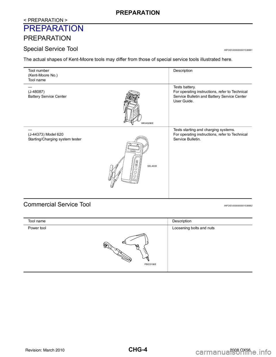
The actual shapes of Kent-Moore tools may differ from those of special service tools illustrated here.
Commercial Service ToolINFOID:0000000001538882
Tool number
(Kent-Moore No.)
Tool name Description
—
(J-48087)
Battery Service Center Te s t s b a t t e r y.
For operating instructions, refer to Technical
Service Bulletin and Battery Service Center
User Guide.
—
(J-44373) Model 620
Starting/Charging system tester Tests starting and charging systems.
For operating instructions, refer to Technical
Service Bulletin.
WKIA5280E
SEL403X
Tool name
Description
Power tool Loosening bolts and nuts
PBIC0190E
Revision: March 2010 2008 QX56
Page 718 of 4083
CHG-6
< BASIC INSPECTION >
DIAGNOSIS AND REPAIR WORKFLOW
NOTE:
To ensure a complete and thorough diagnosis, the battery, starter and generator test segments must be done
as a set from start to finish.
1.PRELIMINARY INSPECTION
Perform the preliminary inspection. Refer to CHG-10, "
Inspection Procedure".
>> GO TO 2.
2.DISABLE THE POWER GENERATION VO LTAGE VARIABLE CONTROL SYSTEM
Disable the power generation voltage variable control with either of the following procedures.
• After selecting “ENGINE” on the “SELECT SYSTEM” screen of CONSULT-III, set the “ALTERNATOR DUTY” value to 0 % by selecting “ALTERNATOR DUTY” with “Active Test”. Continue “Active Test” until the end of
inspection. (When the DUTY value is 0 or 100 %, the normal power generation is performed according to the
characteristic of the IC regulator of the generator.)
• Turn the ignition switch OFF, disconnect the battery current sensor connector and leave it disconnected dur-
ing the course of the test.
NOTE:
Running the engine with the battery current sensor disconnected will cause DTC's (P1550-P1554) to set.
After finishing the inspection, connect the battery current sensor connector and erase the self-diagnostic
results history of the engine using CONSULT-III.
>> GO TO 3.
3.DIAGNOSIS WITH STARTING /CHARGING SYSTEM TESTER
Perform the charging system test using Starting/Charging System Test er (J-44373). For details and operating
instructions, refer to Technical Service Bulletin.
Te s t r e s u l t
CHARGING SYSTEM NOMAL>>Charging system is normal and will also show “DIODE RIPPLE” test result.
NO CHARGING VOLTAGE>>GO TO 4.
LOW CHARGING VOLTAGE>>GO TO 12.
HIGH CHARGING VOLTAGE>>GO TO 14.
DIODE RIPPLE NORMAL>>Diode ripple is OK and will also show “CHARGING VOLTAGE” test result.
EXCESS RIPPLE DETECTED>>Replace the generator. Perf orm “DIODE RIPPLE” test again using Starting/
Charging System Tester (J -44373) to confirm repair.
DIODE RIPPLE NOT DETECTED>>GO TO 4.
4.INSPECTION WITH CHARGE WARNING LAMP (IGNITION SWITCH IS ON)
Turn the ignition switch ON.
Does the charge warning lamp illuminate?
YES >> GO TO 6.
NO >> GO TO 5.
5.TERMINAL“2” (OPEN) CIRCUIT INSPECTION
Check terminal “2” circuit for open circuits. Refer to CHG-14, "
Diagnosis Procedure".
Is the terminal
“2” circuit normal?
YES >> Replace generator.
NO >> Repair as needed.
6.INSPECTION WITH CHARGE WARNING LAMP (IDLING)
Start the engine and run it at idle.
Does the charge warning lamp turn OFF?
YES >> GO TO 9.
NO >> GO TO 7.
7.TERMINAL “2”(SHORT) CIRCUIT INSPECTION
Check terminal “2” circuit for short to ground. Refer to CHG-14, "
Diagnosis Procedure".
Is the terminal
“2” circuit normal?
Revision: March 2010 2008 QX56
Page 725 of 4083

CHG
B TERMINAL CIRCUITCHG-13
< COMPONENT DIAGNOSIS >
C
DE
F
G H
I
J
K L
B A
O P
N
B TERMINAL CIRCUIT
DescriptionINFOID:0000000001696186
The terminal “1” circuit supplies power to charge the battery and operate the vehicles electrical system.
Diagnosis ProcedureINFOID:0000000001696187
1.CHECK TERMINAL “1” CONNECTION
1. Turn ignition switch OFF.
2. Verify terminal “1” is clean and tight.
Is the inspection result normal?
YES >> GO TO 2
NO >> Repair terminal “1” connection. Confirm repa ir by performing complete Starting/Charging system
test. Refer to Technical Service Bulletin.
2.CHECK TERMINAL “1” CIRCUIT
Check voltage between generator connector E204 terminal 1 and
ground.
Is voltage reading as specified?
YES >> GO TO 3.
NO >> Check harness for open between generator and fusible link.
3.CHECK TERMINAL “1” CONNECTION (VOLTAGE DROP TEST)
1. Start engine, then engine running at idle and warm.
2. Check voltage between battery positive terminal and generator connector E204 terminal 1.
Is the voltage reading as specified?
YES >> Terminal “1” circuit is normal. Refer to CHG-5, "Work
Flow".
NO >> Check harness between battery and generator for high resistance.
(+) (-) Voltage
Connector Terminal
E204 1Ground Battery voltage
ALMIA0197ZZ
(+)
(-)Voltage
Connector Terminal
E204 1 Battery positive terminal Less than 0.2V
ALMIA0198ZZ
Revision: March 2010 2008 QX56
Page 726 of 4083

CHG-14
< COMPONENT DIAGNOSIS >
L TERMINAL CIRCUIT
L TERMINAL CIRCUIT
DescriptionINFOID:0000000001696188
The terminal “2” (L) circuit controls the charge warning lamp. The charge warning lamp illuminates when the
ignition switch is set to ON or START. When the generator is providing sufficient voltage with the engine run-
ning, the charge warning lamp will go off. If the c harge warning lamp illuminates with the engine running, a
malfunction is indicated.
Diagnosis ProcedureINFOID:0000000001696189
1.CHECK CHARGE WARNING LAMP CIRCUIT CONNECTION
Verify generator connector E205 terminal 2 is clean and tight.
Is the connection secure?
YES >> GO TO 2
NO >> Repair the connection. Confirm repair by per forming complete Starting/Charging system test.
Refer to Technical Service Bulletin.
2.CHECK CHARGE WARNING LAMP CIRCUIT
1. Disconnect generator connector E205.
2. Apply ground to generator harness connector E205 terminal 2 with the ignition switch in the ON position.
Does the charge lamp illuminate?
YES >> Check generator function. Refer to CHG-5, "Work Flow".
NO >> GO TO 3
3.CHECK HARNESS CONTINUITY
1. Turn ignition switch OFF.
2. Disconnect the generator connector E205 and combination meter connector M24.
3. Check continuity between generator harness connector E205 (A) terminal 2 and combination meter harness connector M24
(B) terminal 6.
4. Check continuity between generator harness connector E205 (A) terminal 2 and ground.
Are the continuity results as specified?
YES >> Replace the combination meter. Refer to MWI-76, "Removal and Installation".
NO >> Repair the harness or connector. Charge lamp should illuminate
ALMIA0200ZZ
AB
Continuity
Connector Terminal Connector Terminal
E205 2M24 6Yes
A —
Continuity
Connector Terminal
E205 2Ground No
AWMIA0596ZZ
Revision: March 2010 2008 QX56
Page 727 of 4083
CHG
S TERMINAL CIRCUITCHG-15
< COMPONENT DIAGNOSIS >
C
DE
F
G H
I
J
K L
B A
O P
N
S TERMINAL CIRCUIT
DescriptionINFOID:0000000001696190
The output voltage of the generator is controlled by the IC
regulator at terminal “3” (S) detecting the input volt-
age. Terminal “3” circuit detects the battery voltage to adjust the generator output voltage with the IC regulator.
Diagnosis ProcedureINFOID:0000000001696191
1.CHECK VOLTAGE REGULATOR CIRCUIT CONNECTION
Check to see if connector E205 terminal 3 is clean and tight.
Is the inspection result normal?
YES >> GO TO 2
NO >> Repair terminal connection. Confirm repair by performing complete Starting/Charging system test.
Refer to Technical Service Bulletin.
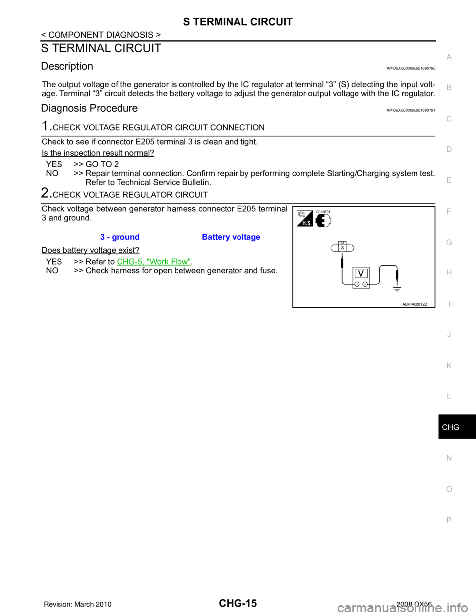
2.CHECK VOLTAGE REGULATOR CIRCUIT
Check voltage between generator harness connector E205 terminal
3 and ground.
Does battery voltage exist?
YES >> Refer to CHG-5, "Work Flow".
NO >> Check harness for open between generator and fuse. 3 - ground
Battery voltage
ALMIA0201ZZ
Revision: March 2010 2008 QX56
Page 2771 of 4083

PG-4
< PREPARATION >
PREPARATION
PREPARATION
PREPARATION
Special Service ToolINFOID:0000000001538889
The actual shapes of Kent-Moore tools may differ from those of special service tools illustrated here.
Commercial Service ToolINFOID:0000000001538890
Tool number
(Kent-Moore No.)
Tool name Description
—
(J-48087)
Battery Service Center Te s t s b a t t e r y.
For operating instructions, refer to Technical
Service Bulletin and Battery Service Center
User Guide.
—
(J-44373) Model 620
Starting/Charging system tester Tests starting and charging systems.
For operating instructions, refer to Technical
Service Bulletin.
WKIA5280E
SEL403X
Tool name
Description
Power tool Loosening bolts and nuts
PBIC0190E
Revision: March 2010 2008 QX56
Page 3533 of 4083

STR-4
< PREPARATION >
PREPARATION
PREPARATION
PREPARATION
Special Service ToolINFOID:0000000001538875
The actual shapes of Kent-Moore tools may differ from those of special service tools illustrated here.
Commercial Service ToolINFOID:0000000001538876
Tool number
(Kent-Moore No.)
Tool name Description
—
(J-48087)
Battery Service Center Te s t s b a t t e r y.
For operating instructions, refer to Technical
Service Bulletin and Battery Service Center
User Guide.
—
(J-44373) Model 620
Starting/Charging system tester Tests starting and charging systems.
For operating instructions, refer to Technical
Service Bulletin.
WKIA5280E
SEL403X
Tool name
Description
Power tool Loosening bolts and nuts
PBIC0190E
Revision: March 2010 2008 QX56
Page 3535 of 4083
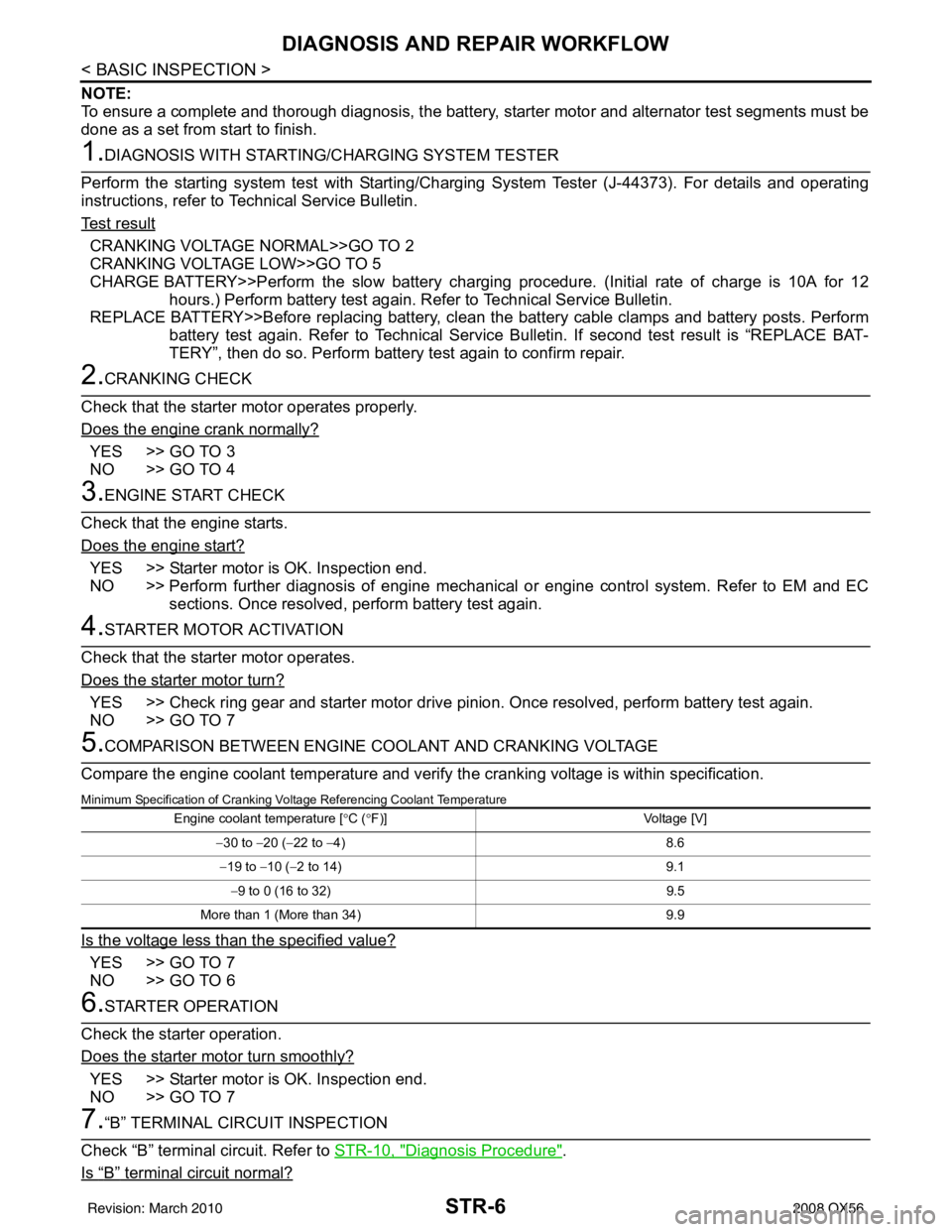
STR-6
< BASIC INSPECTION >
DIAGNOSIS AND REPAIR WORKFLOW
NOTE:
To ensure a complete and thorough diagnosis, the battery, starter motor and alternator test segments must be
done as a set from start to finish.
1.DIAGNOSIS WITH STARTING/CHARGING SYSTEM TESTER
Perform the starting system test with Starting/Charging System Tester (J-44373). For details and operating
instructions, refer to Technical Service Bulletin.
Te s t r e s u l t
CRANKING VOLTAGE NORMAL>>GO TO 2
CRANKING VOLTAGE LOW>>GO TO 5
CHARGE BATTERY>>Perform the slow battery charging procedure. (Initial rate of charge is 10A for 12
hours.) Perform battery test again. Refer to Technical Service Bulletin.
REPLACE BATTERY>>Before replacing battery, clean t he battery cable clamps and battery posts. Perform
battery test again. Refer to Technical Service Bulletin. If second test result is “REPLACE BAT-
TERY”, then do so. Perform battery test again to confirm repair.
2.CRANKING CHECK
Check that the starter motor operates properly.
Does the engine crank normally?
YES >> GO TO 3
NO >> GO TO 4
3.ENGINE START CHECK
Check that the engine starts.
Does the engine start?
YES >> Starter motor is OK. Inspection end.
NO >> Perform further diagnosis of engine mechanical or engine control system. Refer to EM and EC sections. Once resolved, perform battery test again.
4.STARTER MOTOR ACTIVATION
Check that the starter motor operates.
Does the starter motor turn?
YES >> Check ring gear and starter motor drive pinion. Once resolved, perform battery test again.
NO >> GO TO 7
5.COMPARISON BETWEEN ENGINE COOLANT AND CRANKING VOLTAGE
Compare the engine coolant temperature and verify the cranking voltage is within specification.
Minimum Specification of Cranking Voltage Referencing Coolant Temperature
Is the voltage less than the specified value?
YES >> GO TO 7
NO >> GO TO 6
6.STARTER OPERATION
Check the starter operation.
Does the starter motor turn smoothly?
YES >> Starter motor is OK. Inspection end.
NO >> GO TO 7
7.“B” TERMINAL CIRCUIT INSPECTION
Check “B” terminal circuit. Refer to STR-10, "
Diagnosis Procedure".
Is
“B” terminal circuit normal?
Engine coolant temperature [ °C ( °F)] Voltage [V]
− 30 to − 20 (−22 to − 4) 8.6
− 19 to −10 ( −2 to 14) 9.1
− 9 to 0 (16 to 32) 9.5
More than 1 (More than 34) 9.9
Revision: March 2010 2008 QX56