boot INFINITI QX56 2008 Factory Service Manual
[x] Cancel search | Manufacturer: INFINITI, Model Year: 2008, Model line: QX56, Model: INFINITI QX56 2008Pages: 4083, PDF Size: 81.73 MB
Page 449 of 4083
FRONT DISC BRAKEBR-29
< ON-VEHICLE REPAIR >
C
DE
G H
I
J
K L
M A
B
BR
N
O P
FRONT DISC BRAKE
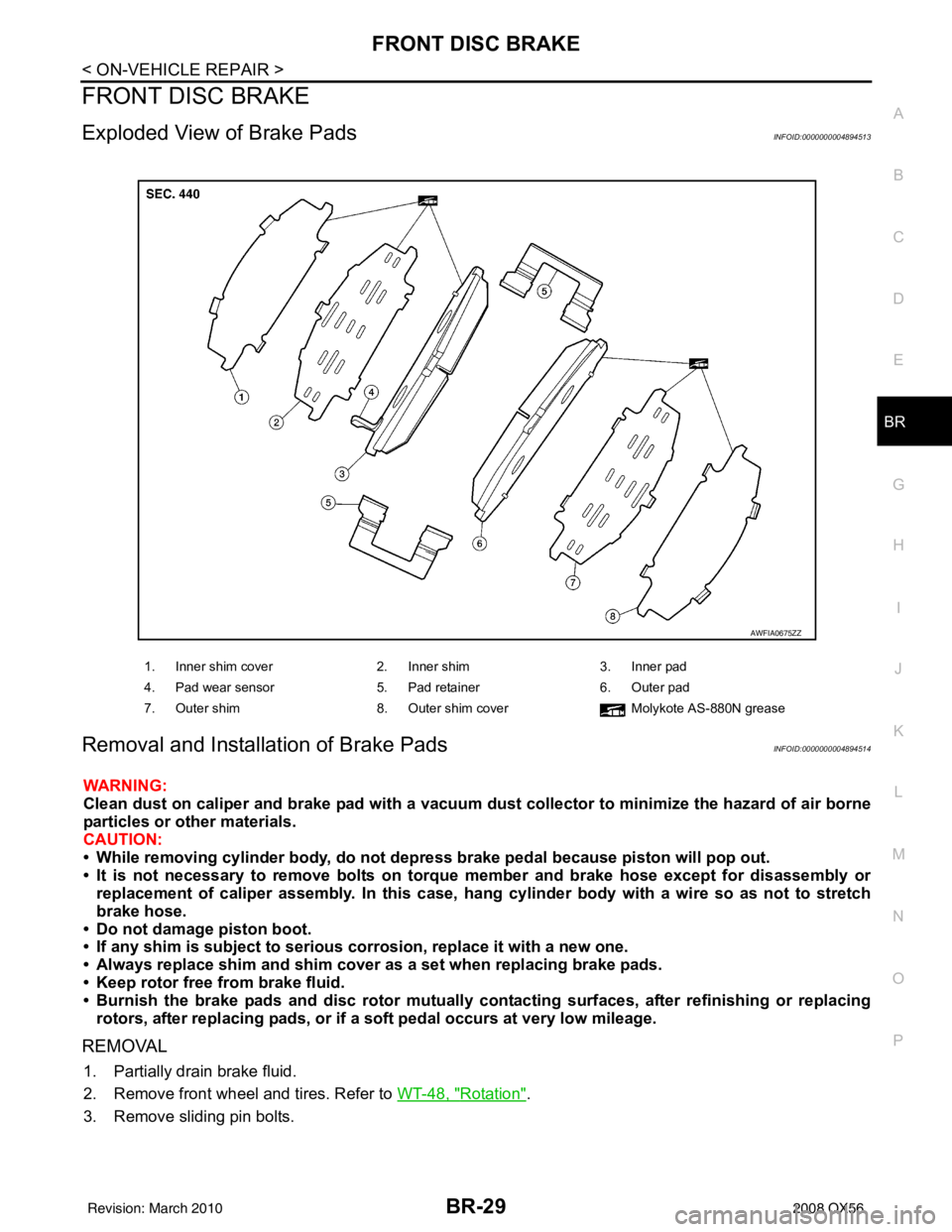
Exploded View of Brake PadsINFOID:0000000004894513
Removal and Installation of Brake PadsINFOID:0000000004894514
WARNING:
Clean dust on caliper and brake pad with a vacuum dust collector to minimize the hazard of air borne
particles or other materials.
CAUTION:
• While removing cylinder bod y, do not depress brake pedal because piston will pop out.
• It is not necessary to remove bolts on torque member and brake hose except for disassembly or replacement of caliper assembly. In this case, hang cylinder body with a wire so as not to stretch
brake hose.
• Do not damage piston boot.
• If any shim is subject to serious corrosion, replace it with a new one.
• Always replace shim and shim cover as a set when replacing brake pads.
• Keep rotor free from brake fluid.
• Burnish the brake pads and disc rotor mutually contacting surfaces, after refinishing or replacing rotors, after replacing pads, or if a so ft pedal occurs at very low mileage.
REMOVAL
1. Partially drain brake fluid.
2. Remove front wheel and tires. Refer to WT-48, "
Rotation".
3. Remove sliding pin bolts.
1. Inner shim cover 2. Inner shim3. Inner pad
4. Pad wear sensor 5. Pad retainer6. Outer pad
7. Outer shim 8. Outer shim cover Molykote AS-880N grease
AWFIA0675ZZ
Revision: March 2010 2008 QX56
Page 451 of 4083
FRONT DISC BRAKEBR-31
< ON-VEHICLE REPAIR >
C
DE
G H
I
J
K L
M A
B
BR
N
O P
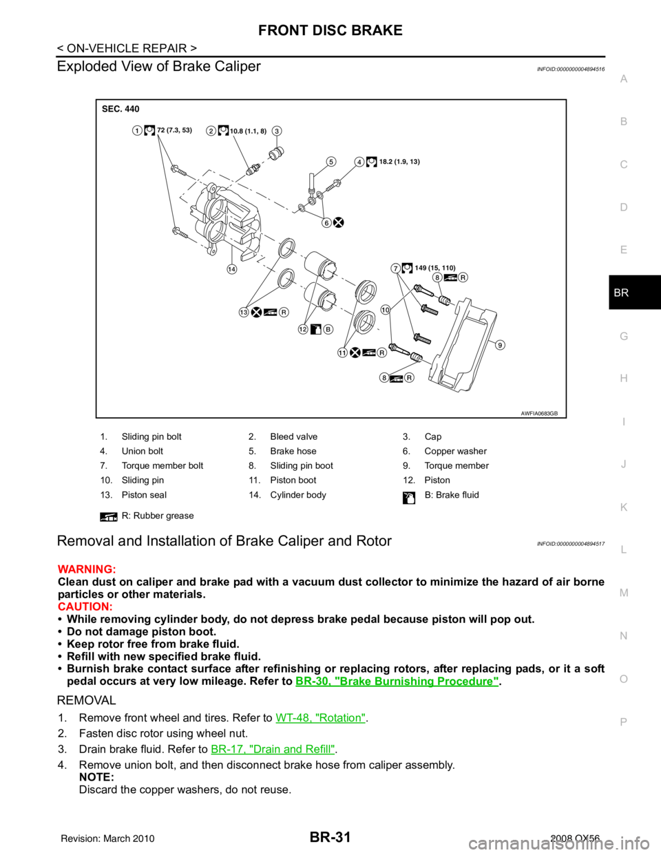
Exploded View of Brake CaliperINFOID:0000000004894516
Removal and Installation of Brake Caliper and RotorINFOID:0000000004894517
WARNING:
Clean dust on caliper and brake pad with a vacuum dust collector to minimize the hazard of air borne
particles or other materials.
CAUTION:
• While removing cylinder bod y, do not depress brake pedal because piston will pop out.
• Do not damage piston boot.
• Keep rotor free from brake fluid.
• Refill with new specified brake fluid.
• Burnish brake contact surface after refinishing or replacing rotors, after replacing pads, or it a soft
pedal occurs at very low mileage. Refer to BR-30, "
Brake Burnishing Procedure".
REMOVAL
1. Remove front wheel and tires. Refer to WT-48, "Rotation".
2. Fasten disc rotor using wheel nut.
3. Drain brake fluid. Refer to BR-17, "
Drain and Refill".
4. Remove union bolt, and then disconnect brake hose from caliper assembly. NOTE:
Discard the copper washers, do not reuse.
1. Sliding pin bolt 2. Bleed valve 3. Cap
4. Union bolt 5. Brake hose 6. Copper washer
7. Torque member bolt 8. Sliding pin boot 9. Torque member
10. Sliding pin 11. Piston boot 12. Piston
13. Piston seal 14. Cylinder body B: Brake fluid
R: Rubber grease
AWFIA0683GB
Revision: March 2010 2008 QX56
Page 454 of 4083
BR-34
< ON-VEHICLE REPAIR >
REAR DISC BRAKE
REAR DISC BRAKE
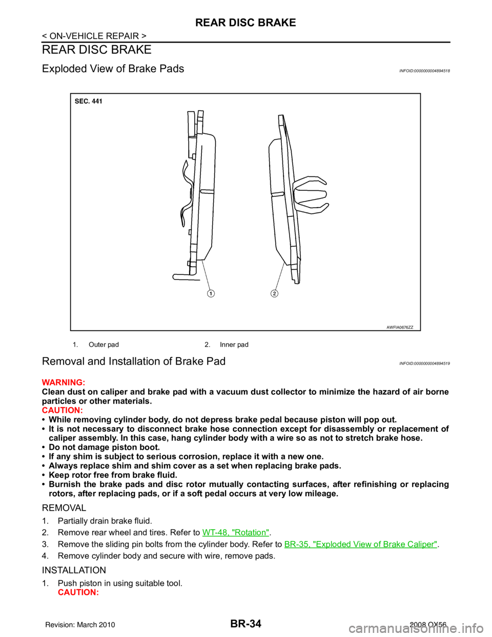
Exploded View of Brake PadsINFOID:0000000004894518
Removal and Installation of Brake PadINFOID:0000000004894519
WARNING:
Clean dust on caliper and brake pad with a vacuum dust collector to minimize the hazard of air borne
particles or other materials.
CAUTION:
• While removing cylinder body, do not depress brake pedal because piston will pop out.
• It is not necessary to disconnect brake hose connection except for disassembly or replacement of caliper assembly. In this case, ha ng cylinder body with a wire so as not to stretch brake hose.
• Do not damage piston boot.
• If any shim is subject to serious corrosion, replace it with a new one.
• Always replace shim and shim cover as a set when replacing brake pads.
• Keep rotor free from brake fluid.
• Burnish the brake pads and disc rotor mutually contacting surfaces, after refinishing or replacing
rotors, after replacing pads, or if a soft pedal occurs at very low mileage.
REMOVAL
1. Partially drain brake fluid.
2. Remove rear wheel and tires. Refer to WT-48, "
Rotation".
3. Remove the sliding pin bolts from the cylinder body. Refer to BR-35, "
Exploded View of Brake Caliper".
4. Remove cylinder body and secure with wire, remove pads.
INSTALLATION
1. Push piston in using suitable tool. CAUTION:
1. Outer pad 2. Inner pad
AWFIA0676ZZ
Revision: March 2010 2008 QX56
Page 456 of 4083
BR-36
< ON-VEHICLE REPAIR >
REAR DISC BRAKE
Removal and Installation of Brake Caliper and Disc Rotor
INFOID:0000000004894522
WARNING:
Clean dust on caliper and brake pad with a vacuum dust collector to minimize the hazard of air borne
particles or other materials.
CAUTION:
• While removing cylinder body, do not depress brake pedal because piston will pop out.
• Do not damage piston boot.
• Keep rotor free from brake fluid.
• Refill with new specified brake fluid.
• Burnish brake contact surface after refinishing or re placing rotors, after replacing pads, or it a soft
pedal occurs at very low mileage. Refer to BR-35, "
Brake Burnishing Procedure".
REMOVAL
1. Remove rear wheel and tires. Refer to WT-48, "Rotation".
2. Fasten disc rotor using wheel nut.
3. Drain brake fluid as necessary. Refer to BR-17, "
Drain and Refill".
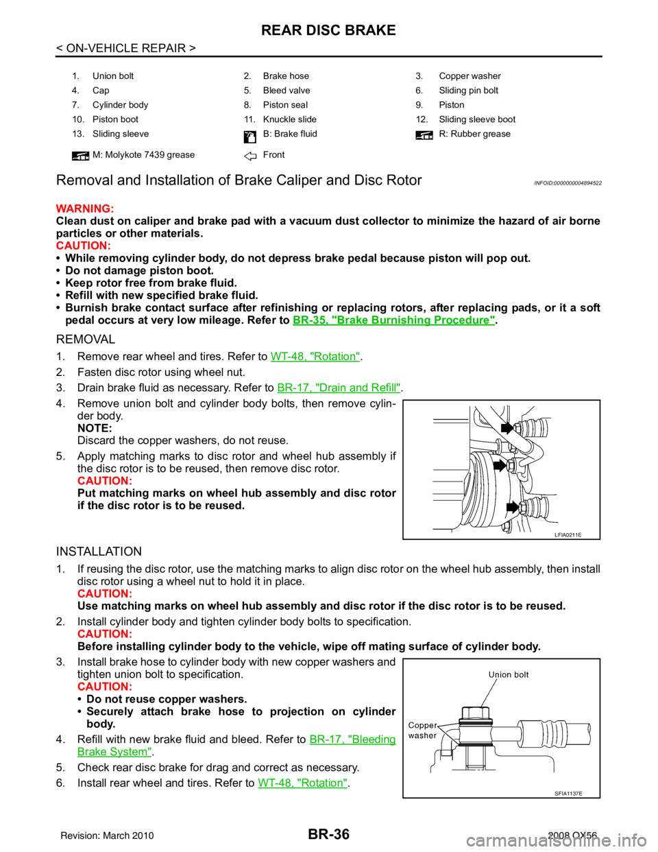
4. Remove union bolt and cylinder body bolts, then remove cylin- der body.
NOTE:
Discard the copper washers, do not reuse.
5. Apply matching marks to disc rotor and wheel hub assembly if the disc rotor is to be reused, then remove disc rotor.
CAUTION:
Put matching marks on wheel hub assembly and disc rotor
if the disc rotor is to be reused.
INSTALLATION
1. If reusing the disc rotor, use the matching marks to align disc rotor on the wheel hub assembly, then install
disc rotor using a wheel nut to hold it in place.
CAUTION:
Use matching marks on wheel hub assembly and di sc rotor if the disc rotor is to be reused.
2. Install cylinder body and tighten cylinder body bolts to specification. CAUTION:
Before installing cylinder body to the vehic le, wipe off mating surface of cylinder body.
3. Install brake hose to cylinder body with new copper washers and tighten union bolt to specification.
CAUTION:
• Do not reuse copper washers.
• Securely attach brake hose to projection on cylinderbody.
4. Refill with new brake fluid and bleed. Refer to BR-17, "
Bleeding
Brake System".
5. Check rear disc brake for drag and correct as necessary.
6. Install rear wheel and tires. Refer to WT-48, "
Rotation".
1. Union bolt 2. Brake hose 3. Copper washer
4. Cap 5. Bleed valve 6. Sliding pin bolt
7. Cylinder body 8. Piston seal9. Piston
10. Piston boot 11. Knuckle slide 12. Sliding sleeve boot
13. Sliding sleeve B: Brake fluidR: Rubber grease
M: Molykote 7439 grease Front
LFIA0211E
SFIA1137E
Revision: March 2010 2008 QX56
Page 459 of 4083
FRONT DISC BRAKEBR-39
< DISASSEMBLY AND ASSEMBLY >
C
DE
G H
I
J
K L
M A
B
BR
N
O P
FRONT DISC BRAKE
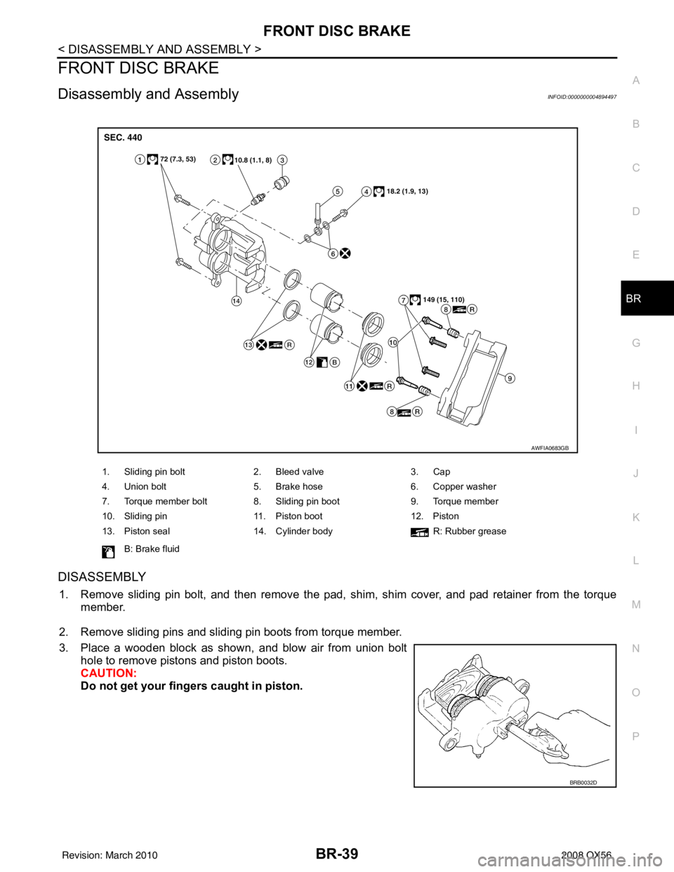
Disassembly and AssemblyINFOID:0000000004894497
DISASSEMBLY
1. Remove sliding pin bolt, and then remove the pad, shim, shim cover, and pad retainer from the torque member.
2. Remove sliding pins and sliding pin boots from torque member.
3. Place a wooden block as shown, and blow air from union bolt hole to remove pistons and piston boots.
CAUTION:
Do not get your fingers caught in piston.
1. Sliding pin bolt 2. Bleed valve 3. Cap
4. Union bolt 5. Brake hose 6. Copper washer
7. Torque member bolt 8. Sliding pin boot 9. Torque member
10. Sliding pin 11. Piston boot 12. Piston
13. Piston seal 14. Cylinder body R: Rubber grease
B: Brake fluid
AWFIA0683GB
BRB0032D
Revision: March 2010 2008 QX56
Page 460 of 4083
BR-40
< DISASSEMBLY AND ASSEMBLY >
FRONT DISC BRAKE
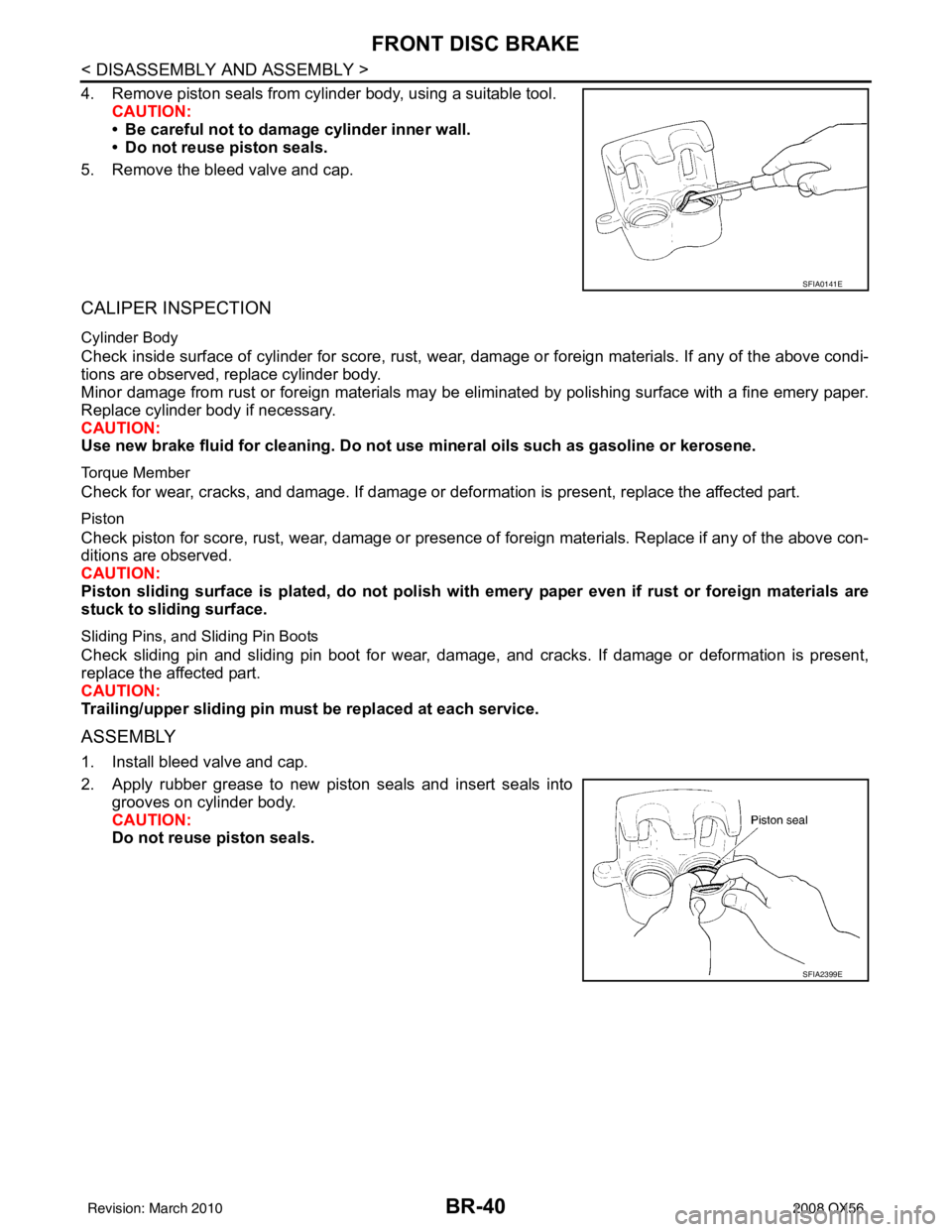
4. Remove piston seals from cylinder body, using a suitable tool.CAUTION:
• Be careful not to damage cylinder inner wall.
• Do not reuse piston seals.
5. Remove the bleed valve and cap.
CALIPER INSPECTION
Cylinder Body
Check inside surface of cylinder for score, rust, wear, damage or foreign materials. If any of the above condi-
tions are observed, replace cylinder body.
Minor damage from rust or foreign materials may be el iminated by polishing surface with a fine emery paper.
Replace cylinder body if necessary.
CAUTION:
Use new brake fluid for cleaning. Do not use mineral oils such as gasoline or kerosene.
Torque Member
Check for wear, cracks, and damage. If damage or def ormation is present, replace the affected part.
Piston
Check piston for score, rust, wear, damage or presence of foreign materials. Replace if any of the above con-
ditions are observed.
CAUTION:
Piston sliding surface is plated, do not polish with emery paper even if rust or foreign materials are
stuck to sliding surface.
Sliding Pins, and Sliding Pin Boots
Check sliding pin and sliding pin boot for wear, damage, and cracks. If damage or deformation is present,
replace the affected part.
CAUTION:
Trailing/upper slidi ng pin must be replaced at each service.
ASSEMBLY
1. Install bleed valve and cap.
2. Apply rubber grease to new piston seals and insert seals into
grooves on cylinder body.
CAUTION:
Do not reuse piston seals.
SFIA0141E
SFIA2399E
Revision: March 2010 2008 QX56
Page 461 of 4083
FRONT DISC BRAKEBR-41
< DISASSEMBLY AND ASSEMBLY >
C
DE
G H
I
J
K L
M A
B
BR
N
O P
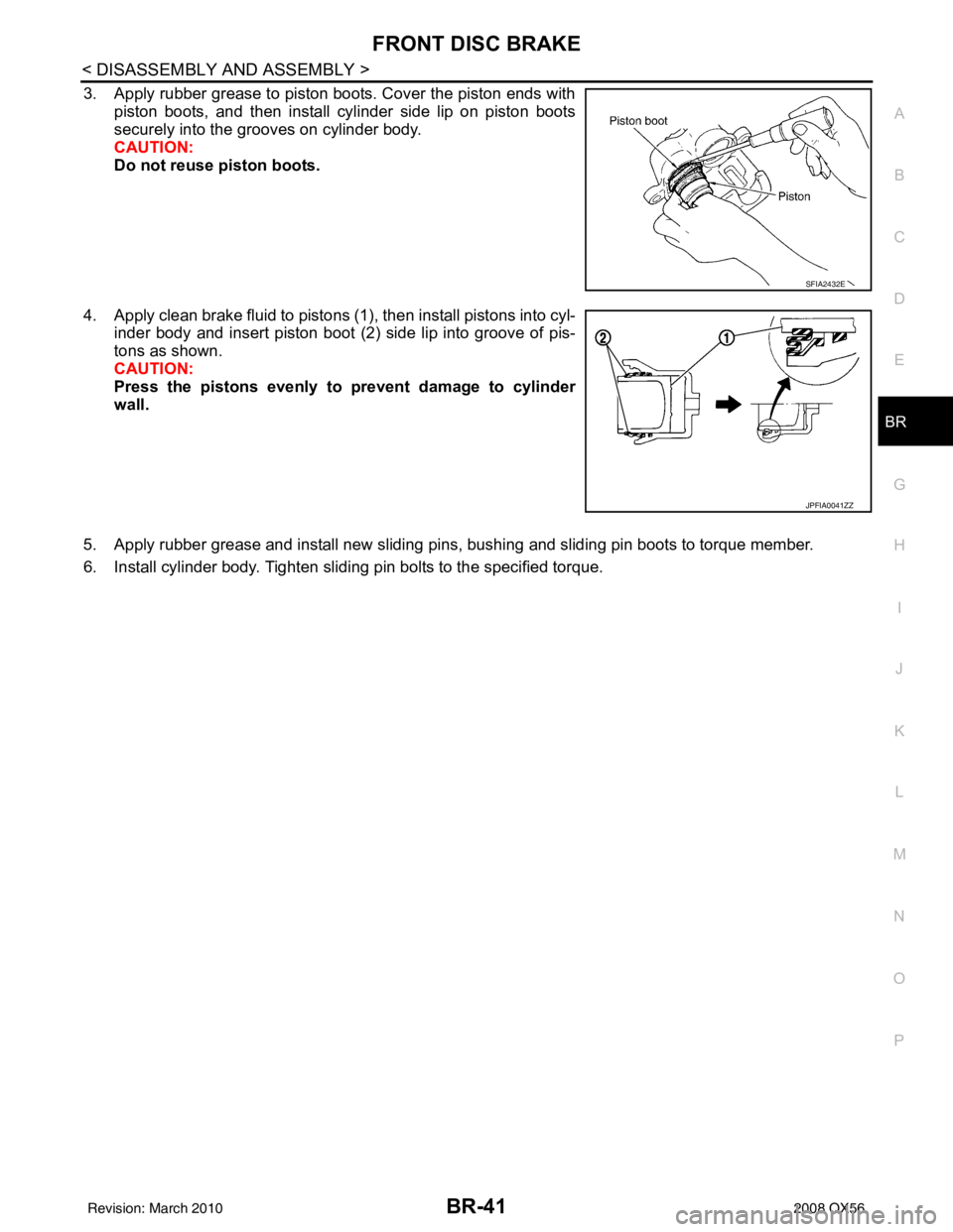
3. Apply rubber grease to piston boots. Cover the piston ends with piston boots, and then install cylinder side lip on piston boots
securely into the grooves on cylinder body.
CAUTION:
Do not reuse piston boots.
4. Apply clean brake fluid to pistons (1), then install pistons into cyl- inder body and insert piston boot (2) side lip into groove of pis-
tons as shown.
CAUTION:
Press the pistons evenly to prevent damage to cylinder
wall.
5. Apply rubber grease and install new sliding pins, bushing and sliding pin boots to torque member.
6. Install cylinder body. Tighten sliding pin bolts to the specified torque.
SFIA2432E
JPFIA0041ZZ
Revision: March 2010 2008 QX56
Page 462 of 4083
BR-42
< DISASSEMBLY AND ASSEMBLY >
REAR DISC BRAKE
REAR DISC BRAKE
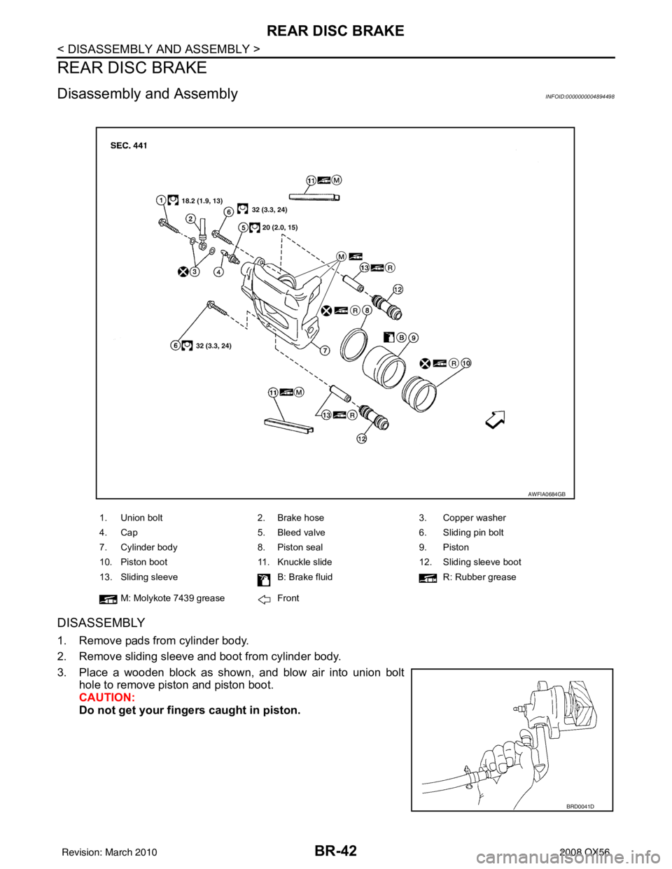
Disassembly and AssemblyINFOID:0000000004894498
DISASSEMBLY
1. Remove pads from cylinder body.
2. Remove sliding sleeve and boot from cylinder body.
3. Place a wooden block as shown, and blow air into union bolthole to remove piston and piston boot.
CAUTION:
Do not get your fingers caught in piston.
1. Union bolt 2. Brake hose 3. Copper washer
4. Cap 5. Bleed valve 6. Sliding pin bolt
7. Cylinder body 8. Piston seal 9. Piston
10. Piston boot 11. Knuckle slide 12. Sliding sleeve boot
13. Sliding sleeve B: Brake fluidR: Rubber grease
M: Molykote 7439 grease Front
AWFIA0684GB
BRD0041D
Revision: March 2010 2008 QX56
Page 463 of 4083
REAR DISC BRAKEBR-43
< DISASSEMBLY AND ASSEMBLY >
C
DE
G H
I
J
K L
M A
B
BR
N
O P
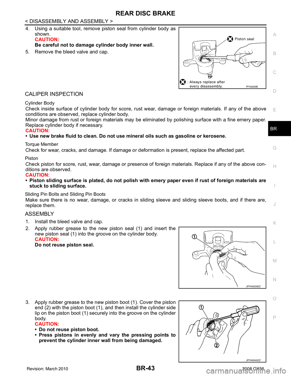
4. Using a suitable tool, remove piston seal from cylinder body as shown.
CAUTION:
Be careful not to damage cylinder body inner wall.
5. Remove the bleed valve and cap.
CALIPER INSPECTION
Cylinder Body
Check inside surface of cylinder body for score, rust wear, damage or foreign materials. If any of the above
conditions are observed, replace cylinder body.
Minor damage from rust or foreign materials may be eliminated by polishing surface with a fine emery paper.
Replace cylinder body if necessary.
CAUTION:
• Use new brake fluid to clean. Do not use mi neral oils such as gasoline or kerosene.
Torque Member
Check for wear, cracks, and damage. If damage or deformation is present, replace the affected part.
Piston
Check piston for score, rust, wear, damage or presence of foreign materials. Replace if any of the above con-
ditions are observed.
CAUTION:
• Piston sliding surface is plated, do not polish with emery paper even if rust of foreign materials are
stuck to sliding surface.
Sliding Pin Bolts and Sliding Pin Boots
Make sure there is no wear, damage, or cracks in sliding sleeve and sliding sleeve boots, and if there are,
replace them.
ASSEMBLY
1. Install the bleed valve and cap.
2. Apply rubber grease to the new piston seal (1) and insert the new piston seal (1) into the groove on the cylinder body.
CAUTION:
Do not reuse piston seal.
3. Apply rubber grease to the new piston boot (1). Cover the piston end (2) with the piston boot (1), and then install the cylinder side
lip on the piston boot (1) securely into the groove on the cylinder
body.
CAUTION:
• Do not reuse piston boot.
• Press pistons in evenly and vary the pressing points toprevent the cylinder inner wall from being damaged.
PFIA0269E
JPFIA0039ZZ
JPFIA0040ZZ
Revision: March 2010 2008 QX56
Page 464 of 4083
BR-44
< DISASSEMBLY AND ASSEMBLY >
REAR DISC BRAKE
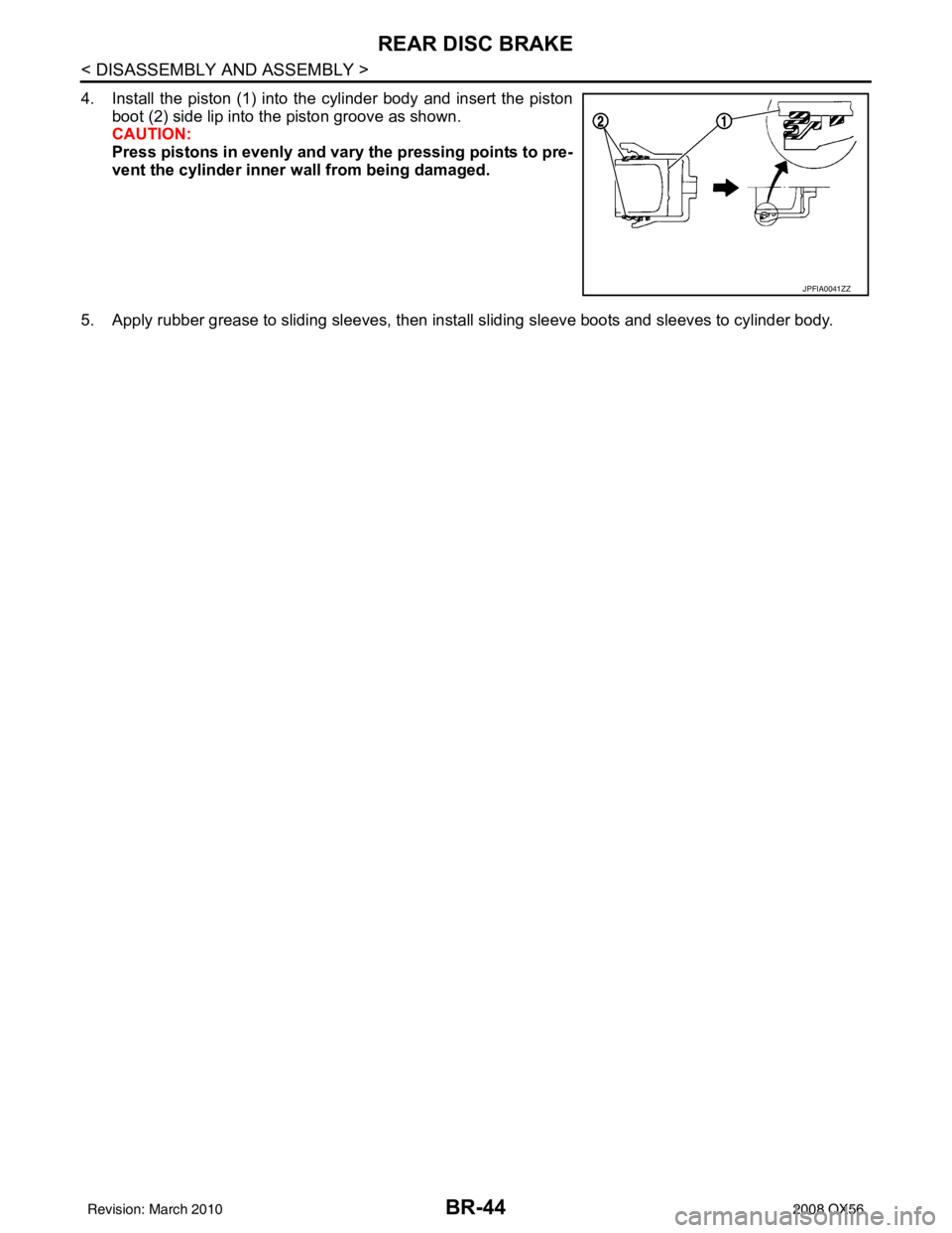
4. Install the piston (1) into the cylinder body and insert the pistonboot (2) side lip into the piston groove as shown.
CAUTION:
Press pistons in evenly and vary the pressing points to pre-
vent the cylinder inner wall from being damaged.
5. Apply rubber grease to sliding sleeves, then inst all sliding sleeve boots and sleeves to cylinder body.
JPFIA0041ZZ
Revision: March 2010 2008 QX56