wheel bolt torque INFINITI QX56 2008 Factory Service Manual
[x] Cancel search | Manufacturer: INFINITI, Model Year: 2008, Model line: QX56, Model: INFINITI QX56 2008Pages: 4083, PDF Size: 81.73 MB
Page 449 of 4083

FRONT DISC BRAKEBR-29
< ON-VEHICLE REPAIR >
C
DE
G H
I
J
K L
M A
B
BR
N
O P
FRONT DISC BRAKE
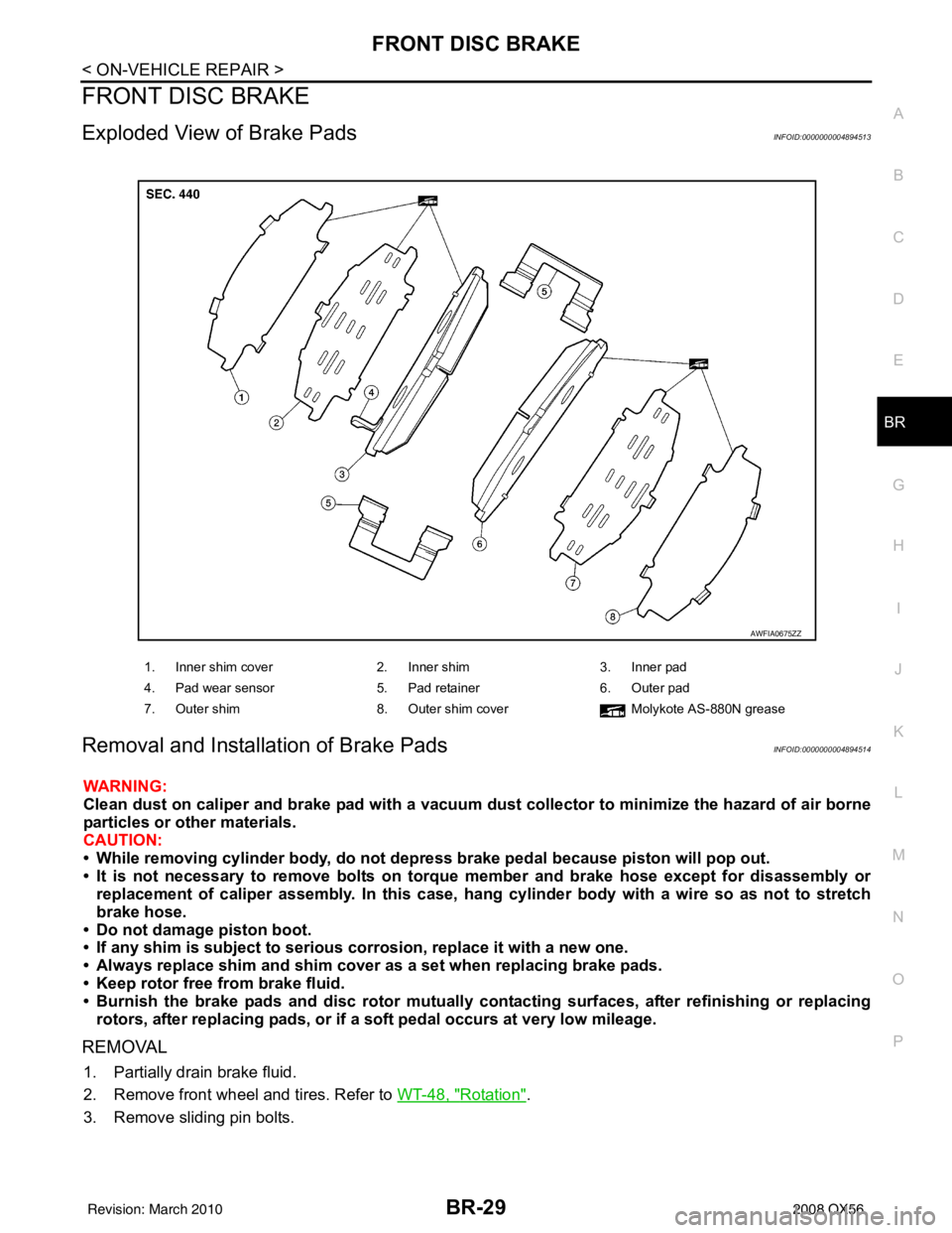
Exploded View of Brake PadsINFOID:0000000004894513
Removal and Installation of Brake PadsINFOID:0000000004894514
WARNING:
Clean dust on caliper and brake pad with a vacuum dust collector to minimize the hazard of air borne
particles or other materials.
CAUTION:
• While removing cylinder bod y, do not depress brake pedal because piston will pop out.
• It is not necessary to remove bolts on torque member and brake hose except for disassembly or replacement of caliper assembly. In this case, hang cylinder body with a wire so as not to stretch
brake hose.
• Do not damage piston boot.
• If any shim is subject to serious corrosion, replace it with a new one.
• Always replace shim and shim cover as a set when replacing brake pads.
• Keep rotor free from brake fluid.
• Burnish the brake pads and disc rotor mutually contacting surfaces, after refinishing or replacing rotors, after replacing pads, or if a so ft pedal occurs at very low mileage.
REMOVAL
1. Partially drain brake fluid.
2. Remove front wheel and tires. Refer to WT-48, "
Rotation".
3. Remove sliding pin bolts.
1. Inner shim cover 2. Inner shim3. Inner pad
4. Pad wear sensor 5. Pad retainer6. Outer pad
7. Outer shim 8. Outer shim cover Molykote AS-880N grease
AWFIA0675ZZ
Revision: March 2010 2008 QX56
Page 450 of 4083

BR-30
< ON-VEHICLE REPAIR >
FRONT DISC BRAKE
4. Hang cylinder body with a wire, and remove pads, pad retainers,shims, and shim cover from torque member.
CAUTION:
When removing the pad retainer from the torque member,
lift it in the direction indi cated by the arrow as shown so
that it does not deform.
INSTALLATION
1. Push piston in using suitable tool.
CAUTION:
In the case of replacing a pad with new one, ch eck the brake fluid level in the reservoir tank
because brake fluid returns to reservoir tank when pressing piston in.
NOTE:
Use a suitable tool to easily press in piston.
2. Apply Molykote AS-880N grease or equivalent to between shim cover and shim. Install inner shim, inner shim cover to inner pad, and install outer shim, outer shim cover to outer pad.
3. Install pad retainers and pads to torque member. CAUTION:
• Securely assemble pad retainers so that they ar e not being lifted up from torque member.
• Both inner and outer pads have a pad return system on the pad retainer. Install pad return lever
securely to pad wear sensor.
4. Install cylinder body to torque member.
5. Install sliding pin bolts, and tighten to specified torque. Refer to BR-31, "
Exploded View of Brake Caliper".
6. Check front disc brake for drag and correct as necessary.
7. Install front wheel and tire. Refer to WT-48, "
Rotation".
8. Check brake fluid level. Refer to BR-17, "
On Board Inspection".
Brake Burnishing ProcedureINFOID:0000000004894515
Burnish contact surfaces between disc rotors and pads according to following procedure after refinishing or
replacing rotors, after replacing pads, or if a soft pedal occurs at very low mileage.
CAUTION:
• Be careful of vehicle speed because the brake does not operate easily until pad and disc rotor are securely seated.
• Only perform this procedure under safe road and traffic conditions. Use extreme caution.
1. Drive vehicle on straight, flat road.
2. Depress brake pedal with the power to stop vehicle within 3 to 5 seconds until the vehicle stops.
3. Drive without depressing brake for a few minutes to cool the brake.
4. Repeat steps 1 through 3 until pad and disc rotor are securely seated.
SBR556E
Revision: March 2010 2008 QX56
Page 451 of 4083

FRONT DISC BRAKEBR-31
< ON-VEHICLE REPAIR >
C
DE
G H
I
J
K L
M A
B
BR
N
O P
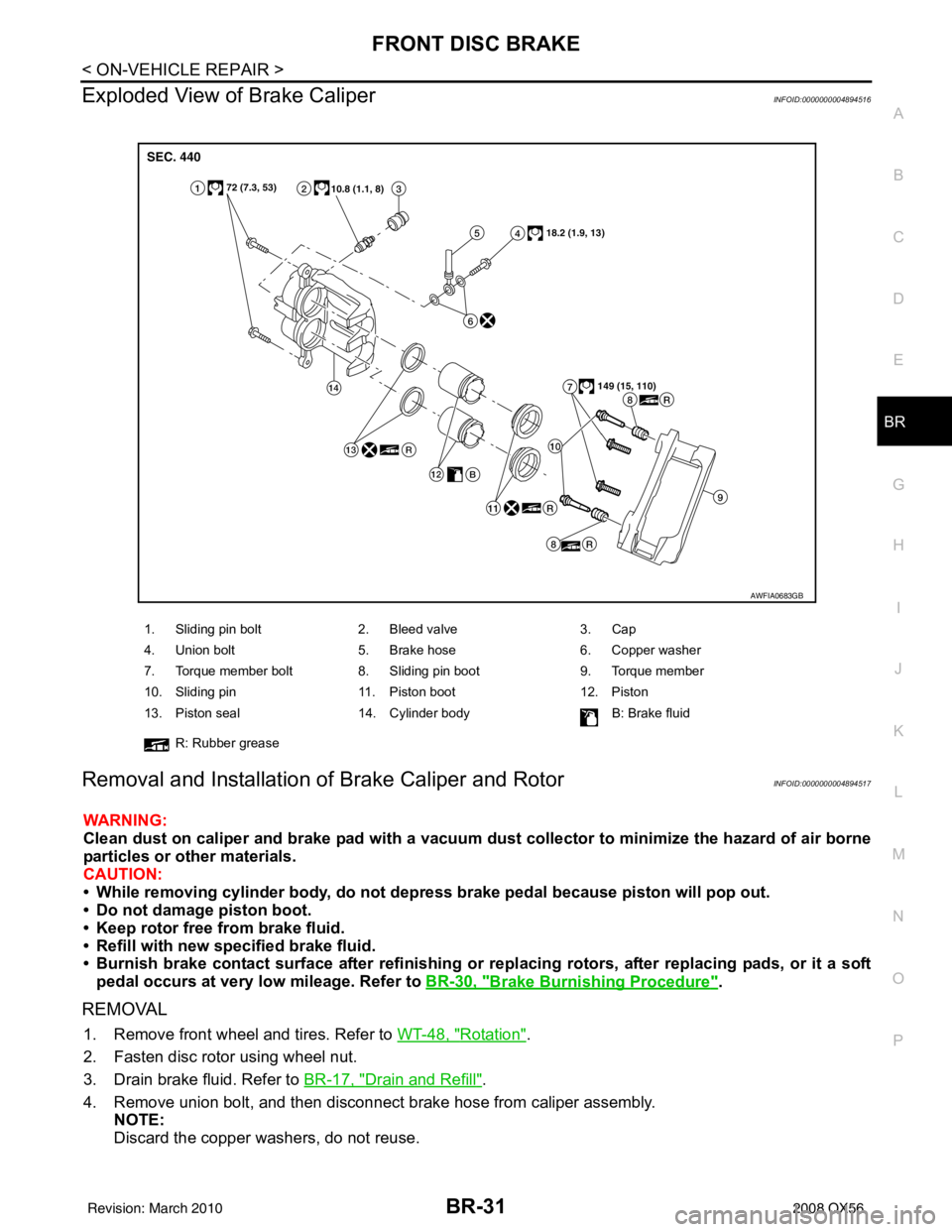
Exploded View of Brake CaliperINFOID:0000000004894516
Removal and Installation of Brake Caliper and RotorINFOID:0000000004894517
WARNING:
Clean dust on caliper and brake pad with a vacuum dust collector to minimize the hazard of air borne
particles or other materials.
CAUTION:
• While removing cylinder bod y, do not depress brake pedal because piston will pop out.
• Do not damage piston boot.
• Keep rotor free from brake fluid.
• Refill with new specified brake fluid.
• Burnish brake contact surface after refinishing or replacing rotors, after replacing pads, or it a soft
pedal occurs at very low mileage. Refer to BR-30, "
Brake Burnishing Procedure".
REMOVAL
1. Remove front wheel and tires. Refer to WT-48, "Rotation".
2. Fasten disc rotor using wheel nut.
3. Drain brake fluid. Refer to BR-17, "
Drain and Refill".
4. Remove union bolt, and then disconnect brake hose from caliper assembly. NOTE:
Discard the copper washers, do not reuse.
1. Sliding pin bolt 2. Bleed valve 3. Cap
4. Union bolt 5. Brake hose 6. Copper washer
7. Torque member bolt 8. Sliding pin boot 9. Torque member
10. Sliding pin 11. Piston boot 12. Piston
13. Piston seal 14. Cylinder body B: Brake fluid
R: Rubber grease
AWFIA0683GB
Revision: March 2010 2008 QX56
Page 452 of 4083

BR-32
< ON-VEHICLE REPAIR >
FRONT DISC BRAKE
5. Remove torque member bolts, and remove brake caliperassembly.
CAUTION:
Do not drop brake pad.
6. Apply matching marks to disc rotor and wheel hub assembly as shown if the disc rotor is to be reused, then remove disc rotor.
CAUTION:
Put matching marks on wheel hub assembly and disc rotor
if the disc rotor is to be reused.
INSTALLATION
1. If reusing the disc rotor, use the matching marks to align discrotor on the wheel hub assembly as shown, then install disc
rotor using a wheel nut to hold it in place.
CAUTION:
Use matching marks on wheel hub assembly and disc rotor
if the disc rotor is to be reused.
2. Install brake caliper assembly to vehicle, and tighten torque member bolts to the specified torque.
CAUTION:
Do not allow oil or any moisture on all contact surfaces
between steering knuckle and caliper assembly, bolts, and
washer.
SFIA2437E
SDIA2608E
SDIA2608E
SFIA2437E
Revision: March 2010 2008 QX56
Page 453 of 4083

FRONT DISC BRAKEBR-33
< ON-VEHICLE REPAIR >
C
DE
G H
I
J
K L
M A
B
BR
N
O P
3. Install brake hose to brake caliper assembly using new copper washers. Align the brake hose to the projection as shown and
tighten union bolts to the specified torque.
CAUTION:
• Do not reuse copper washers.
• Securely attach brake hose to projection on cylinderbody.
4. Refill with new brake fluid and bleed air. Refer to BR-17, "
Bleeding Brake System".
5. Check front disc brake for drag and correct as necessary.
6. Install front wheel and tires. Refer to WT-48, "
Rotation".
SFIA2431E
Revision: March 2010 2008 QX56
Page 455 of 4083

REAR DISC BRAKEBR-35
< ON-VEHICLE REPAIR >
C
DE
G H
I
J
K L
M A
B
BR
N
O P
By pushing in piston, br ake fluid returns to master cylinder reservoir tank. Watch the brake fluid
level in the reservoir tank.
NOTE:
Using a suitable tool, makes it easier to push in the piston.
2. Apply Molykote AS-880N grease to knuckle slide where brake pads contact. CAUTION:
Do not get grease on the brake pads or brake rotor friction surfaces.
3. Install pads to cylinder body.
4. Install cylinder body to torque member.
5. Install cylinder body sliding pin bolts and tighten to specification. Refer to BR-35, "
Exploded View of Brake
Caliper".
6. Check rear disc brake for drag.
7. Install rear wheel and tires. Refer to WT-48, "
Rotation".
8. Check brake fluid level. Refer to BR-17, "
On Board Inspection"
Brake Burnishing ProcedureINFOID:0000000004894520
Burnish contact surfaces between disc rotors and pads according to following procedure after refinishing or
replacing rotors, after replacing pads, or if a soft pedal occurs at very low mileage.
CAUTION:
• Be careful of vehicle speed because the brake does not operate easily until pad and disc rotor are securely seated.
• Only perform this procedure under safe road and traffic conditions. Use extreme caution.
1. Drive vehicle on straight, flat road.
2. Depress brake pedal with the power to stop vehicle within 3 to 5 seconds until the vehicle stops.
3. Drive without depressing brake for a few minutes to cool the brake.
4. Repeat steps 1 through 3 until pad and disc rotor are securely seated.
Exploded View of Brake CaliperINFOID:0000000004894521
AWFIA0684GB
Revision: March 2010 2008 QX56
Page 2091 of 4083

WHEEL HUBFAX-7
< REMOVAL AND INSTALLATION >
CEF
G H
I
J
K L
M A
B
FA X
N
O P
REMOVAL AND INSTALLATION
WHEEL HUB
Removal and InstallationINFOID:0000000001534453
REMOVAL
1. Remove wheel and tire using power tool.
2. Remove engine under cover using power tool.
3. Without disassembling the hydraulic lines, remove caliper torque member bolts using power tool. Then
reposition brake caliper aside with wire. Refer to BR-31, "
Removal and Installation of Brake Caliper and
Rotor" .
NOTE:
Do not press brake pedal while brake caliper is removed.
4. Put alignment mark on disc rotor and wheel hub and bearing assembly, then remove disc rotor.
5. On 4WD model, remove cotter pin, then remove lock nut from drive shaft using power tool. Then remove end of drive shaft from wheel hub and bearing assembly. Refer to FAX-9, "
Removal and Installation" .
6. Remove wheel sensor. Refer to BRC-114, "
Removal and Installation" .
• Inspect the wheel sensor O-ring, replac e the wheel sensor assembly if damaged.
• Clean the wheel sensor hole and mounting surface with a suitable brake cleaner and clean lint-free shop rag. Be careful that dirt and debris do not enter the axle bearing area.
• Apply a coat of suitable grease to the wheel sensor O-ring and mounting hole.
CAUTION:
Do not pull on the wheel sensor harness.
7. Remove wheel hub and bearing assembly bolts using power tool.
1. Disc rotor 2. Wheel hub and bearing assembly 3. Wheel stud
4. Splash guard 5. Steering knuckle Front
AWDIA0423GB
WDIA0044E
Revision: March 2010 2008 QX56
Page 2124 of 4083

ON-VEHICLE SERVICEFSU-7
< ON-VEHICLE MAINTENANCE >
C
DF
G H
I
J
K L
M A
B
FSU
N
O P
ON-VEHICLE MAINTENANCE
ON-VEHICLE SERVICE
Front Suspension PartsINFOID:0000000001534627
Check front suspension parts for excessive play, cracks, wear and
other damage.
• Shake each front wheel to check for excessive play. If looseness is noted, inspect wheel bearing end play, then check
ball joint end play. Refer to FA X - 6 , "
On-Vehicle Inspection and Ser-
vice" and FSU-7, "Front Suspension Parts".
• Make sure that the cotter pin is inserted (4WD only).
• Retighten all nuts and bolts to the specified torque.
• Check shock absorber for oil leakage and other damage.
• Check suspension ball joint for grease leakage and ball joint dust cover for cracks and other damage.
Front Wheel AlignmentINFOID:0000000004915023
PRELIMINARY INSPECTION
WARNING:
Always adjust the alignment with the vehicle on a flat surface.
NOTE:
If alignment is out of specificat ion, inspect and replace any damaged or worn suspension parts before making
any adjustments.
1. Check and adjust the wheel alignment with the vehicle under unladen conditions. “Unladen conditions”
means that the fuel, coolant, and lubricant are full; and that the spare tire, jack, hand tools and mats are in
their designated positions.
2. Check the tires for incorrect air pressure and excessive wear.
3. Check the wheels for run out and damage. Refer to WT-45, "
Inspection".
4. Check the wheel bearing axial end play. Refer to FAX-6, "
On-Vehicle Inspection and Service" .
5. Check the shock absorbers for leaks or damage.
6. Check each mounting point of the suspension components for any excessive looseness or damage.
7. Check each link, arm, and the rear suspension member for any damage.
8. Check the vehicle height. Refer to FSU-25, "
Wheelarch Height (Unladen*1)" .
GENERAL INFORMATION AND RECOMMENDATIONS
1. A Four-Wheel Thrust Alignment should be performed.
• This type of alignment is re commended for any NISSAN vehicle.
• The four-wheel “thrust” process helps ensure that the vehicle is properly aligned and the steering wheel
is centered.
• The alignment machine itself should be ca pable of accepting any NISSAN vehicle.
• The alignment machine should be checked to ensure that it is level.
2. Make sure the alignment machine is properly calibrated. Suspension component torques : Refer to
FSU-14,
"Component" . SMA525A
SFA392B
Revision: March 2010 2008 QX56
Page 2138 of 4083

KNUCKLEFSU-21
< REMOVAL AND INSTALLATION >
C
DF
G H
I
J
K L
M A
B
FSU
N
O P
7. Remove pinch bolt from steering knuckle using power tool, then separate lower link ball joint from steering knuckle.
8. Remove steering knuckle from vehicle.
INSPECTION AFTER REMOVAL
Check for deformity, cracks and damage on each part, replace if necessary.
• Perform ball joint inspection. Refer to FSU-11, "
Inspection" .
INSTALLATION
Installation is in the reverse order of removal.
• Refer to FSU-14, "
Component" for tightening torques.
CAUTION:
Use a new cotter pin for installation of lock nut.
• When installing disc rotor on wheel hub and bearing assembly, align the marks.
NOTE:
When not using the alignment mark, refer to BR-7, "
DISC ROTOR
: Inspection" .
• When installing wheel and tire, refer to WT-48, "
Rotation" .
LEIA0097E
WDIA0044E
Revision: March 2010 2008 QX56
Page 2142 of 4083

SERVICE DATA AND SPECIFICATIONS (SDS)FSU-25
< SERVICE DATA AND SPECIFICATIONS (SDS)
C
DF
G H
I
J
K L
M A
B
FSU
N
O P
*2: Target value 37 ° 31 ′ (37.52 °)
*3: Target value 33 ° 59 ′ (33.98 °)
*4: Target value 37 ° 44 ′ (37.73 °)
*5: Target value 33 ° 29 ′ (33.48 °)
*6: Some vehicles may be equipped with straight (non-adjustable) lower link bolts and washers. In order to adjust camber and ca ster on
these vehicles, first replace the lower link bolts and washers with adjustable (cam) bolts and washers.
Ball JointINFOID:0000000001534624
*1 Measure at cotter pin hole
*2 Measure at groove
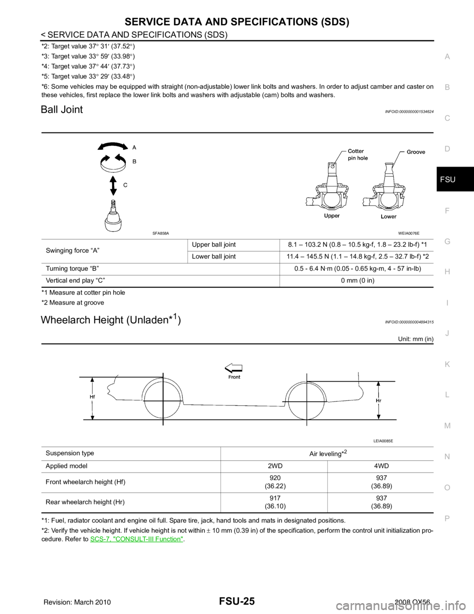
Wheelarch Height (Unladen*1)INFOID:0000000004894315
Unit: mm (in)
*1: Fuel, radiator coolant and engine oil full. Spare tire, jack, hand tools and mats in designated positions.
*2: Verify the vehicle height. If vehicle height is not within ± 10 mm (0.39 in) of the specification, perform the control unit initialization pro-
cedure. Refer to SCS-7, "
CONSULT-III Function".
Swinging force “A”
Upper ball joint 8.1 – 103.2 N (0.8 – 10.5 kg-f, 1.8 – 23.2 lb-f) *1
Lower ball joint 11.4 – 145.5 N (1.1 – 14.8 kg-f, 2.5 – 32.7 lb-f) *2
Turning torque “B” 0.5 - 6.4 N·m (0.05 - 0.65 kg-m, 4 - 57 in-lb)
Vertical end play “C” 0 mm (0 in)
SFA858AWEIA0076E
Suspension type
Air leveling*2
Applied model2WD4WD
Front wheelarch height (Hf) 920
(36.22) 937
(36.89)
Rear wheelarch height (Hr) 917
(36.10) 937
(36.89)
LEIA0085E
Revision: March 2010 2008 QX56