ignition INFINITI QX56 2009 Factory Service Manual
[x] Cancel search | Manufacturer: INFINITI, Model Year: 2009, Model line: QX56, Model: INFINITI QX56 2009Pages: 4171, PDF Size: 84.65 MB
Page 4107 of 4171
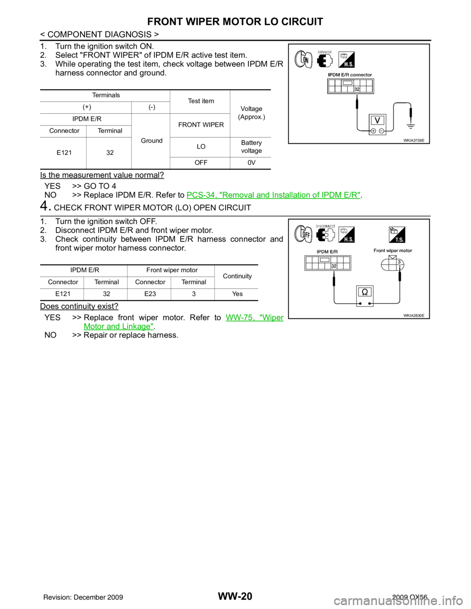
WW-20
< COMPONENT DIAGNOSIS >
FRONT WIPER MOTOR LO CIRCUIT
1. Turn the ignition switch ON.
2. Select "FRONT WIPER" of IPDM E/R active test item.
3. While operating the test item, check voltage between IPDM E/Rharness connector and ground.
Is the measurement value normal?
YES >> GO TO 4
NO >> Replace IPDM E/R. Refer to PCS-34, "
Removal and Installation of IPDM E/R".
4. CHECK FRONT WIPER MOTOR (LO) OPEN CIRCUIT
1. Turn the ignition switch OFF.
2. Disconnect IPDM E/R and front wiper motor.
3. Check continuity between IPDM E/R harness connector and front wiper motor harness connector.
Does continuity exist?
YES >> Replace front wiper motor. Refer to WW-75, "Wiper
Motor and Linkage".
NO >> Repair or replace harness.
Te r m i n a l s Te s t i t e m
Voltage
(Approx.)
(+)
(-)
IPDM E/R
GroundFRONT WIPER
Connector Terminal
E121 32 LO
Battery
voltage
OFF 0V
WKIA3759E
IPDM E/R Front wiper motor
Continuity
Connector Terminal Connector Terminal
E121 32 E233Yes
WKIA2830E
Revision: December 20092009 QX56
Page 4108 of 4171

FRONT WIPER MOTOR HI CIRCUITWW-21
< COMPONENT DIAGNOSIS >
C
DE
F
G H
I
J
K
M A
B
WW
N
O P
FRONT WIPER MOTOR HI CIRCUIT
Component Function CheckINFOID:0000000003776292
1. CHECK FRONT WIPER HI OPERATION
IPDM E/R AUTO ACTIVE TEST
1. Start IPDM E/R auto active test. Refer to PCS-12, "
Diagnosis Description".
2. Check that the front wiper operates at the HI operation.
CONSULT-III ACTIVE TEST
1. Select "FRONT WIPER" of IPDM E/R active test item.
2. While operating the test item, check front wiper operation.
Is front wiper (HI) operation normal?
YES >> Front wiper motor HI circuit is normal.
NO >> Refer to WW-21, "
Diagnosis Procedure".
Diagnosis ProcedureINFOID:0000000003776293
1. CHECK FRONT WIPER MOTOR FUSE
1. Turn the ignition switch OFF.
2. Check that the following fuse is not blown.
Is the fuse blown?
YES >> GO TO 2
NO >> GO TO 3
2. CHECK FRONT WIPER MOTOR (HI) SHORT CIRCUIT
1. Disconnect IPDM E/R and front wiper motor.
2. Check continuity between IPDM E/R harness connector and ground.
Does continuity exist?
YES >> Repair or replace harness.
NO >> Replace the fuse. (Replace IPDM E/R if the fuse is blown again.)
3. CHECK FRONT WIPER MOTOR (HI) OUTPUT VOLTAGE
CONSULT-III ACTIVE TEST HI : Front wiper (HI) operation
OFF : Stop the front wiper.
Unit Location Fuse No. Capacity
Front wiper motor IPDM E/R39 30 A
IPDM E/R
GroundContinuity
Connector Terminal
E121 35 No
ALLIA0448ZZ
Revision: December 20092009 QX56
Page 4109 of 4171
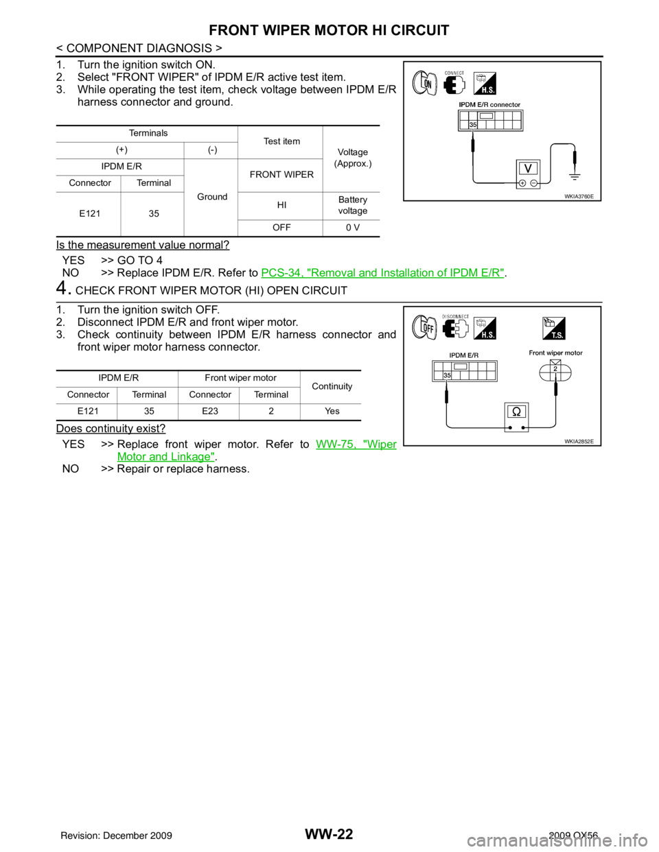
WW-22
< COMPONENT DIAGNOSIS >
FRONT WIPER MOTOR HI CIRCUIT
1. Turn the ignition switch ON.
2. Select "FRONT WIPER" of IPDM E/R active test item.
3. While operating the test item, check voltage between IPDM E/Rharness connector and ground.
Is the measurement value normal?
YES >> GO TO 4
NO >> Replace IPDM E/R. Refer to PCS-34, "
Removal and Installation of IPDM E/R".
4. CHECK FRONT WIPER MOTOR (HI) OPEN CIRCUIT
1. Turn the ignition switch OFF.
2. Disconnect IPDM E/R and front wiper motor.
3. Check continuity between IPDM E/R harness connector and front wiper motor harness connector.
Does continuity exist?
YES >> Replace front wiper motor. Refer to WW-75, "Wiper
Motor and Linkage".
NO >> Repair or replace harness.
Te r m i n a l s Te s t i t e m
Voltage
(Approx.)
(+)
(-)
IPDM E/R
GroundFRONT WIPER
Connector Terminal
E121 35 HI
Battery
voltage
OFF 0 V
WKIA3760E
IPDM E/R Front wiper motor
Continuity
Connector Terminal Connector Terminal
E121 35 E232Yes
WKIA2852E
Revision: December 20092009 QX56
Page 4110 of 4171

FRONT WIPER AUTO STOP SIGNAL CIRCUITWW-23
< COMPONENT DIAGNOSIS >
C
DE
F
G H
I
J
K
M A
B
WW
N
O P
FRONT WIPER AUTO ST OP SIGNAL CIRCUIT
Component Function CheckINFOID:0000000003776294
1. CHECK FRONT WIPER (AUTO STOP) SIGNAL CHECK
CONSULT-III DATA MONITOR
1. Select "FR WIPER STOP" of IPDM E/R data monitor item.
2. Operate the front wiper.
3. Check that "FR WIPER STOP" changes to "ON" and "OFF" linked with the wiper operation.
Is the status of item normal?
YES >> Front wiper auto stop signal circuit is normal.
NO >> Refer to WW-23, "
Diagnosis Procedure".
Diagnosis ProcedureINFOID:0000000003776295
1. CHECK FRONT WIPER MOTOR (A UTO STOP) OUTPUT VOLTAGE
1. Turn the ignition switch ON.
2. Check voltage between IPDM E/R harness connector and ground.
Is the measurement value normal?
YES >> GO TO 3
NO >> GO TO 2
2. CHECK FRONT WIPER MOTOR (AUTO STOP) SHORT CIRCUIT
1. Turn the ignition switch OFF.
2. Disconnect IPDM E/R and front wiper motor.
3. Check continuity between IPDM E/R harness connector and ground.
Does continuity exist?
YES >> Repair or replace harness.
NO >> Replace IPDM E/R. Refer to PCS-34, "
Removal and Installation of IPDM E/R".
3. CHECK FRONT WIPER MOTOR (AUTO STOP) CIRCUIT CONTINUITY
Monitor item ConditionMonitor status
FR WIPER STOP Front wiper motor Stop position
ON
Except stop position OFF
Te r m i n a l s
Voltage
(Approx.)
(+)
(-)
IPDM E/R Ground
Connector Terminal
E122 43 Battery voltage
WKIA1431E
IPDM E/R
GroundContinuity
Connector Terminal
E122 43 No
WKIA1429E
Revision: December 20092009 QX56
Page 4112 of 4171
FRONT WIPER MOTOR GROUND CIRCUITWW-25
< COMPONENT DIAGNOSIS >
C
DE
F
G H
I
J
K
M A
B
WW
N
O P
FRONT WIPER MOTOR GROUND CIRCUIT
Diagnosis ProcedureINFOID:0000000003776296
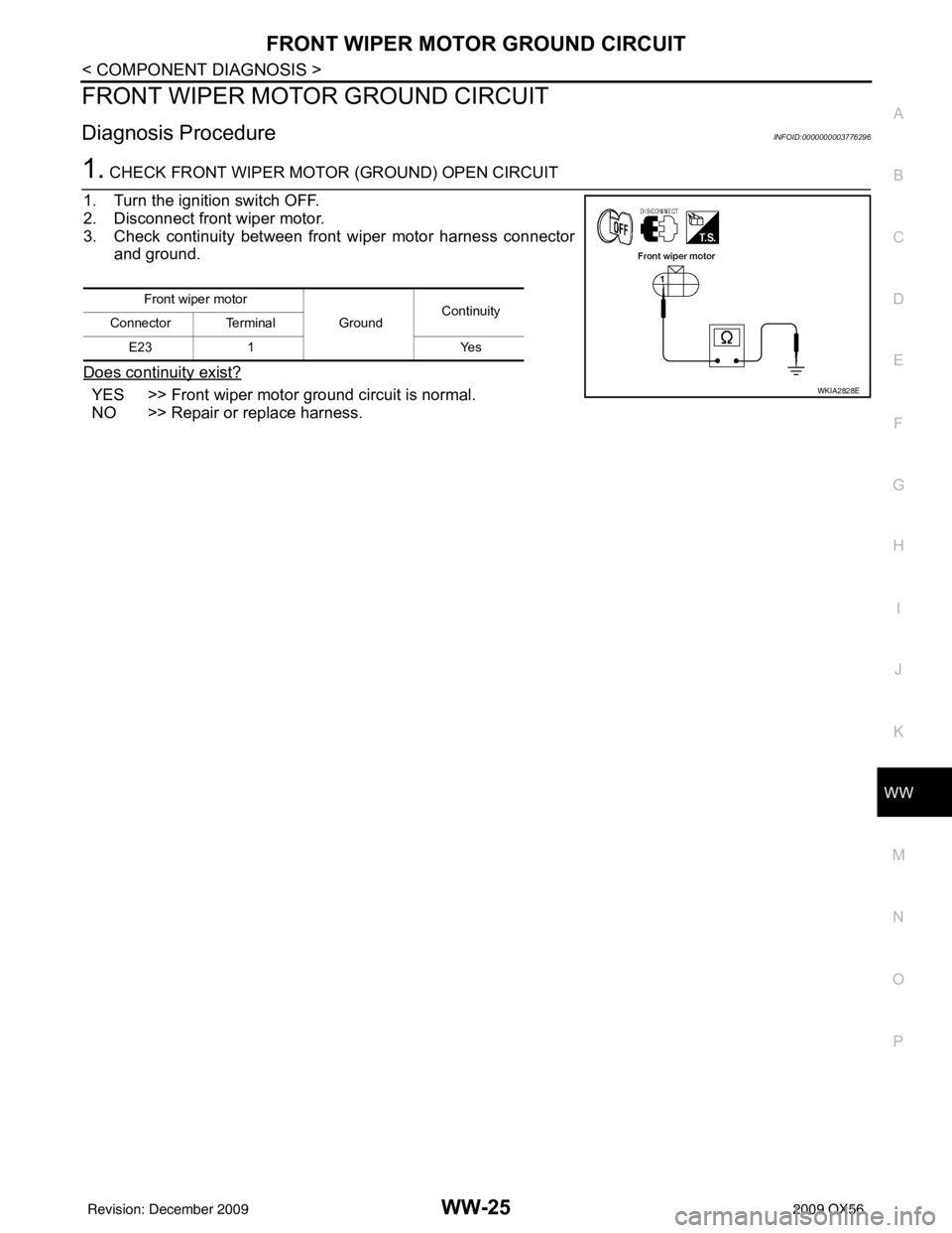
1. CHECK FRONT WIPER MOTO R (GROUND) OPEN CIRCUIT
1. Turn the ignition switch OFF.
2. Disconnect front wiper motor.
3. Check continuity between front wiper motor harness connector and ground.
Does continuity exist?
YES >> Front wiper motor ground circuit is normal.
NO >> Repair or replace harness.
Front wiper motor GroundContinuity
Connector Terminal
E23 1 Yes
WKIA2828E
Revision: December 20092009 QX56
Page 4113 of 4171
WW-26
< COMPONENT DIAGNOSIS >
WASHER SWITCH
WASHER SWITCH
DescriptionINFOID:0000000003776297
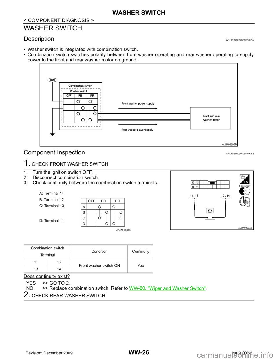
• Washer switch is integrated with combination switch.
• Combination switch switches polarity between front washer operating and rear washer operating to supply
power to the front and rear washer motor on ground.
Component InspectionINFOID:0000000003776298
1. CHECK FRONT WASHER SWITCH
1. Turn the ignition switch OFF.
2. Disconnect combination switch.
3. Check continuity between the combination switch terminals.
Does continuity exist?
YES >> GO TO 2.
NO >> Replace combination switch. Refer to WW-80, "
Wiper and Washer Switch".
2. CHECK REAR WASHER SWITCH
ALLIA0350GB
A: Terminal 14
B: Terminal 12
C: Terminal 13
D: Terminal 11
ALLIA0839ZZJPLIA0164GB
Combination switch ConditionContinuity
Te r m i n a l
11 1 2
Front washer switch ON Yes
13 14
Revision: December 20092009 QX56
Page 4114 of 4171
WASHER SWITCHWW-27
< COMPONENT DIAGNOSIS >
C
DE
F
G H
I
J
K
M A
B
WW
N
O P
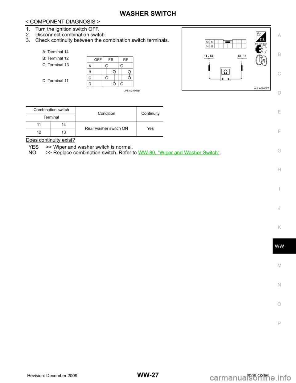
1. Turn the ignition switch OFF.
2. Disconnect combination switch.
3. Check continuity between the combination switch terminals.
Does continuity exist?
YES >> Wiper and washer switch is normal.
NO >> Replace combination switch. Refer to WW-80, "
Wiper and Washer Switch".
A: Terminal 14
B: Terminal 12
C: Terminal 13
D: Terminal 11
ALLIA0840ZZJPLIA0164GB
Combination switch
ConditionContinuity
Te r m i n a l
11 1 4
Rear washer switch ON Yes
12 13
Revision: December 20092009 QX56
Page 4115 of 4171
WW-28
< COMPONENT DIAGNOSIS >
REAR WIPER MOTOR CIRCUIT
REAR WIPER MOTOR CIRCUIT
Component Function CheckINFOID:0000000003776299
1. CHECK REAR WIPER ON OPERATION
CONSULT-III ACTIVE TEST
1. Select "RR WIPER" of BCM active test item.
2. While operating the test item, check rear wiper operation.
Is rear wiper operation normal?
YES >> Rear wiper motor circuit is normal.
NO >> Refer to WW-28, "
Diagnosis Procedure".
Diagnosis ProcedureINFOID:0000000003776300
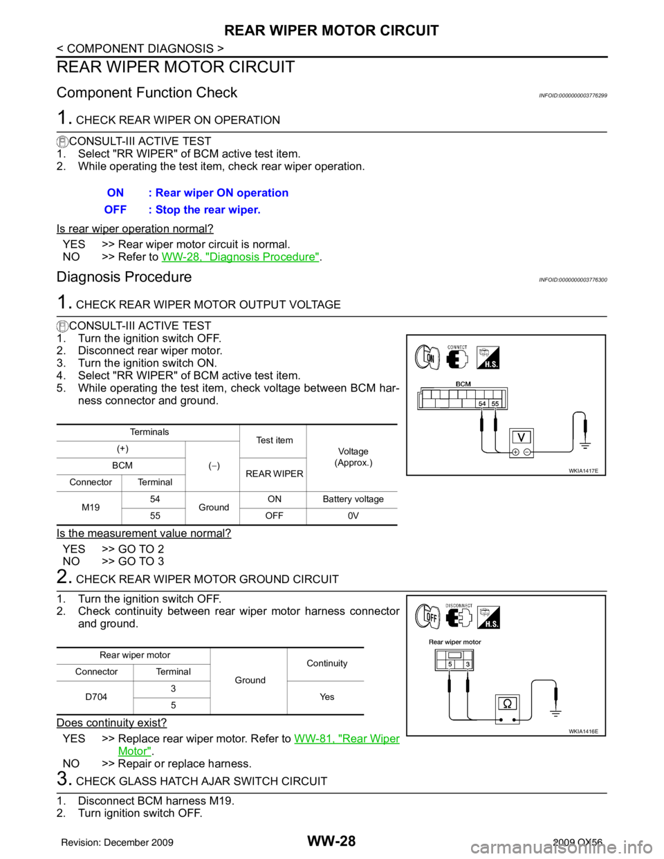
1. CHECK REAR WIPER MOTOR OUTPUT VOLTAGE
CONSULT-III ACTIVE TEST
1. Turn the ignition switch OFF.
2. Disconnect rear wiper motor.
3. Turn the ignition switch ON.
4. Select "RR WIPER" of BCM active test item.
5. While operating the test item, check voltage between BCM har-
ness connector and ground.
Is the measurement value normal?
YES >> GO TO 2
NO >> GO TO 3
2. CHECK REAR WIPER MOTOR GROUND CIRCUIT
1. Turn the ignition switch OFF.
2. Check continuity between rear wiper motor harness connector and ground.
Does continuity exist?
YES >> Replace rear wiper motor. Refer to WW-81, "Rear Wiper
Motor".
NO >> Repair or replace harness.
3. CHECK GLASS HATCH AJAR SWITCH CIRCUIT
1. Disconnect BCM harness M19.
2. Turn ignition switch OFF. ON : Rear wiper ON operation
OFF : Stop the rear wiper.
Te r m i n a l s Te s t i t e m
Vo l ta g e
(Approx.)
(+)
(−)
BCM
REAR WIPER
Connector Terminal
M19 54
Ground ON Battery voltage
55 OFF0V
WKIA1417E
Rear wiper motor
GroundContinuity
Connector Terminal
D704 3
Ye s
5
WKIA1416E
Revision: December 20092009 QX56
Page 4117 of 4171

WW-30
< COMPONENT DIAGNOSIS >
REAR WIPER AUTO STOP SIGNAL CIRCUIT
REAR WIPER AUTO STOP SIGNAL CIRCUIT
Component Function CheckINFOID:0000000003776301
1. CHECK REAR WIPER (AUTO STOP) OPERATION
CONSULT-III DATA MONITOR
1. Select "WIPER" of BCM data monitor item.
2. Operate the rear wiper.
3. Check that "RR WIPER STOP" changes to "O N" and "OFF" linked with the wiper operation.
Is the status of item normal?
YES >> Rear wiper auto stop signal circuit is normal.
NO >> Refer to WW-30, "
Diagnosis Procedure".
Diagnosis ProcedureINFOID:0000000003776302
1. CHECK REAR WIPER MOTOR AUTO STOP CIRCUITS
1. Turn ignition switch OFF.
2. Disconnect BCM and rear wiper motor.
3. Check continuity between BCM harness connector terminals and rear wiper motor harness connector terminals.
Is inspection result normal?
YES >> GO TO 2
NO >> Repair or replace harness.
2. CHECK AUTO STOP CIRCUITS FOR SHORT TO GROUND
Check continuity between BCM harness connector terminals and
ground.
Is inspection result normal?
YES >> Replace BCM. Refer to BCS-56, "Removal and Installa-
tion".
NO >> Repair or replace harness.
Monitor item ConditionMonitor status
RR WIPER STOP Rear wiper motor Stop position
ON
Except stop position OFF
BCM Rear wiper motor
Continuity
Connector Terminal Connector Terminal
M18 26 D7041
Ye s
M19 44 2
WKIA1415E
BCM
GroundContinuity
Connector Terminal
M18 26 No
M19 44
WKIA1421E
Revision: December 20092009 QX56
Page 4129 of 4171

WW-42
< ECU DIAGNOSIS >
BCM (BODY CONTROL MODULE)
HEADLAMP SW1Headlamp switch OFF OFF
Headlamp switch 1st
ON
HEADLAMP SW2 Headlamp switch OFF
OFF
Headlamp switch 1st ON
HI BEAM SW High beam switch OFF
OFF
High beam switch HI ON
H/L WASH SW NOTE:
The item is indicated, but not monitored OFF
IGN ON SW Ignition switch OFF or ACC
OFF
Ignition switch ON ON
IGN SW CAN Ignition switch OFF or ACC
OFF
Ignition switch ON ON
INT VOLUME Wiper intermittent dial is in a dial position 1 - 7 1 - 7
I-KEY LOCK LOCK button of Intelligent Key is not pressed
OFF
LOCK button of Intelligent Key is pressed ON
I-KEY UNLOCK UNLOCK button of Intelligent Key is not pressed
OFF
UNLOCK button of Intelligent Key is pressed ON
KEY ON SW Mechanical key is removed from key cylinder
OFF
Mechanical key is inserted to key cylinder ON
OIL PRESS SW • Ignition switch OFF or ACC
• Engine running
OFF
Ignition switch ON ON
PASSING SW Other than lighting switch PASS
OFF
Lighting switch PASS ON
REAR DEF SW Rear window defogger switch OFF
OFF
Rear window defogger switch ON ON
RKE LOCK AND UN-
LOCK NOTE:
The item is indicated, but not monitored OFF
ON
RR WASHER SW Rear washer switch OFF
OFF
Rear washer switch ON ON
RR WIPER INT Rear wiper switch OFF
OFF
Rear wiper switch INT ON
RR WIPER ON Rear wiper switch OFF
OFF
Rear wiper switch ON ON
RR WIPER STOP Rear wiper stop position
OFF
Other than rear wiper stop position ON
TAIL LAMP SW Lighting switch OFF
OFF
Lighting switch 1ST ON
TRNK OPNR SW When back door opener switch is not pressed
OFF
When back door opener switch is pressed ON
TURN SIGNAL L Turn signal switch OFF
OFF
Turn signal switch LH ON
TURN SIGNAL R Turn signal switch OFF
OFF
Turn signal switch RH ON
VEHICLE SPEED While driving Equivalent to speedometer reading
Monitor Item
Condition Value/Status
Revision: December 20092009 QX56