warning INFINITI QX56 2009 Factory Service Manual
[x] Cancel search | Manufacturer: INFINITI, Model Year: 2009, Model line: QX56, Model: INFINITI QX56 2009Pages: 4171, PDF Size: 84.65 MB
Page 1870 of 4171
TIMING CHAINEM-47
< ON-VEHICLE REPAIR >
C
DE
F
G H
I
J
K L
M A
EM
NP
O
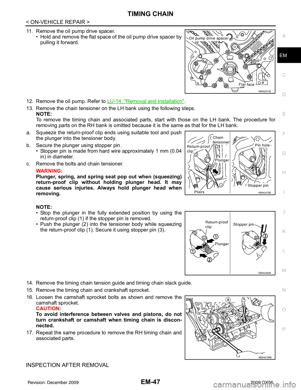
11. Remove the oil pump drive spacer.
• Hold and remove the flat space of the oil pump drive spacer bypulling it forward.
12. Remove the oil pump. Refer to LU-14, "
Removal and Installation".
13. Remove the chain tensioner on the LH bank using the following steps. NOTE:
To remove the timing chain and associated parts, start with those on the LH bank. The procedure for
removing parts on the RH bank is omitted because it is the same as that for the LH bank.
a. Squeeze the return-proof clip ends using suitable tool and push the plunger into the tensioner body.
b. Secure the plunger using stopper pin. • Stopper pin is made from hard wire approximately 1 mm (0.04in) in diameter.
c. Remove the bolts and chain tensioner.
WARNING:
Plunger, spring, an d spring seat pop out when (squeezing)
return-proof clip without holding plunger head. It may
cause serious injuries. Always hold plunger head when
removing.
NOTE:
• Stop the plunger in the fully extended position by using the
return-proof clip (1) if the stopper pin is removed.
• Push the plunger (2) into the tensioner body while squeezing
the return-proof clip (1). Secure it using stopper pin (3).
14. Remove the timing chain tension guide and timing chain slack guide.
15. Remove the timing chain and crankshaft sprocket.
16. Loosen the camshaft sprocket bolts as shown and remove the camshaft sprocket.
CAUTION:
To avoid interference between valves and pistons, do not
turn crankshaft or camshaft wh en timing chain is discon-
nected.
17. Repeat the same procedure to remove the RH timing chain and associated parts.
INSPECTION AFTER REMOVAL
KBIA2512E
KBIA2479E
KBIA2483E
WBIA0799E
Revision: December 20092009 QX56
Page 1877 of 4171

EM-54
< ON-VEHICLE REPAIR >
CAMSHAFT
5. Obtain compression TDC of No. 1 cylinder as follows:
a. Turn the crankshaft pulley clockwise to align the TDC identifica-tion notch (without paint mark) with the timing indicator on the
front cover.
b. At this time, make sure both intake and exhaust cam lobes of No. 1 cylinder (top front on LH bank) point outside.
• If they do not point outside, turn crankshaft pulley once more.
6. Disconnect and remove the camshaft position sensor. Refer to EM-44, "
Exploded View".
7. Disconnect and remove the intake valve timing c ontrol position sensor (RH and LH). Refer to EM-44,
"Exploded View".
8. Disconnect and remove the intake valve timing control solenoid valve (RH and LH). Refer to EM-44,
"Exploded View".
9. Remove the intake valve timing control solenoid cover RH bank (A) and intake valve timing control solenoid cover LH bank (B)
as follows:
a. Loosen and remove the bolts in reverse order as shown.
b. Cut the liquid gasket and remove the covers using Tool.
CAUTION:
Do not damage mating surfaces.
10. Paint alignment marks on the RH bank (A) timing chain links (C) and LH bank (B) timing chain links (D) and align with the cam-
shaft sprocket alignment marks (E) and (F).
11. Remove the chain tensioner (LH) using the following steps. WARNING:
Plunger, spring, and spring seat pop out when squeezing return-proof clip without holding
plunger head. It may cause serious injuries. Always hold plunger head when removing.
KBIA2476E
KBIA0400J
Tool number : KV10111100 (J-37228)
AWBIA0815ZZ
AWBIA0154ZZ
Revision: December 20092009 QX56
Page 1878 of 4171
CAMSHAFTEM-55
< ON-VEHICLE REPAIR >
C
DE
F
G H
I
J
K L
M A
EM
NP
O
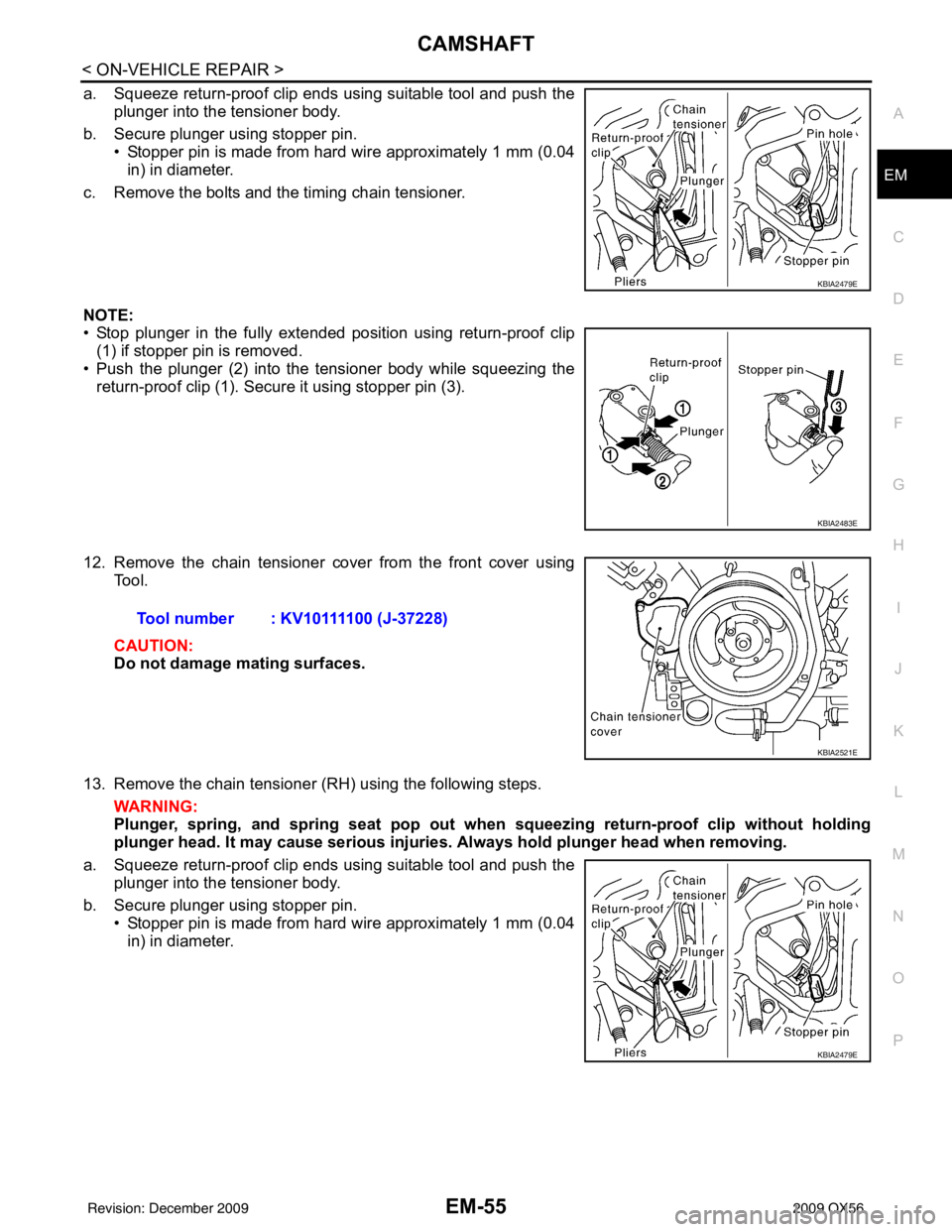
a. Squeeze return-proof clip ends using suitable tool and push the
plunger into the tensioner body.
b. Secure plunger using stopper pin. • Stopper pin is made from hard wire approximately 1 mm (0.04in) in diameter.
c. Remove the bolts and the timing chain tensioner.
NOTE:
• Stop plunger in the fully extended position using return-proof clip (1) if stopper pin is removed.
• Push the plunger (2) into the tensioner body while squeezing the return-proof clip (1). Secure it using stopper pin (3).
12. Remove the chain tensioner cover from the front cover using Tool.
CAUTION:
Do not damage mating surfaces.
13. Remove the chain tensioner (RH) using the following steps. WARNING:
Plunger, spring, and spring seat pop out when squeezing return -proof clip without holding
plunger head. It may cause serious injuries. Always hold plunger head when removing.
a. Squeeze return-proof clip ends using suitable tool and push the plunger into the tensioner body.
b. Secure plunger using stopper pin. • Stopper pin is made from hard wire approximately 1 mm (0.04in) in diameter.
KBIA2479E
KBIA2483E
Tool number : KV10111100 (J-37228)
KBIA2521E
KBIA2479E
Revision: December 20092009 QX56
Page 1885 of 4171

EM-62
< ON-VEHICLE REPAIR >
CAMSHAFT
5. Install the camshaft sprockets using the following procedure:• A: LH bank shown
a. Install the camshaft sprockets aligning them with the matching marks painted on the timing chain (B) and the camshaft sprock-
ets (C) before removal. Align the camshaft sprocket key groove
with the dowel pin on the camshaft front edge at the same time.
Then temporarily tighten camshaft sprocket bolts.
• Install the intake (VTC) (A) and exhaust (B) side camshaft
sprockets by selectively using the groove of the dowel pin
according to the bank for the exhaust (B) side camshaft
sprockets. (Common part used for both exhaust banks.)
NOTE:
Use the groove marked "R" for RH bank and "L" for LH bank.
b. Lock the hexagonal part of the camshaft in the same way as for removal, and tighten the camshaft sprocket bolts.
c. Check again that the timing alignment mark on the timing chain and on each sprocket are aligned.
6. Install the chain tensioner using the following procedure: NOTE:
LH is shown.
a. Install the chain tensioner. • Compress the plunger and hold it using a stopper pin wheninstalling.
• Loosen the slack guide side timing chain by rotating the cam- shaft hexagonal part if mounting space is small.
b. Remove the stopper pin and release the plunger, and then apply tension to the timing chain.
c. Install the chain tensioner cover onto the front cover. • Apply liquid gasket as shown.
Use Genuine RTV Silicone Seal ant or equivalent. Refer to
GI-15, "
Recommended Chemical Products and Sealants".
7. Check and adjust valve clearances. Refer to EM-18, "
Va l v e
Clearance".
8. Installation of the remaining components is in the reverse order of removal.
Inspection after InstallationINFOID:0000000005885890
INSPECTION OF CAMSHAFT SPROCKET (INT) OIL GROOVE
WARNING:
• Check when engine is cold so as to pr event burns from any splashing engine oil.
CAUTION:
AWBIA0152ZZ
AWBIA0151ZZ
Chain tensioner bolts : 6.9 N·m (0.70 kg-m, 61 in-lb)
Chain tensioner cover
bolts : 9.0 N·m (0.92 kg-m, 80 in-lb)KBIA2479E
KBIA2547E
Revision: December 20092009 QX56
Page 1886 of 4171

CAMSHAFTEM-63
< ON-VEHICLE REPAIR >
C
DE
F
G H
I
J
K L
M A
EM
NP
O
• Perform this inspection only when
DTC P0011 is detected in self-diagnostic results of CONSULT III
and it is directed according to inspecti on procedure of EC section. Refer to EC-87, "
On Board Diag-
nosis Logic".
1. Check engine oil level. Refer to LU-8, "
Inspection".
2. Perform the following procedure so as to prevent the engine from being unintentionally started while checking.
a. Release fuel pressure. Refer to EC-487, "
Fuel Pressure Check".
b. Disconnect ignition coil and injector harness connectors if practical.
3. Remove IVT control solenoid valve.
4. Crank engine, and then make sure that engine oil comes out from IVT control cover oil hole. End cranking after checking.
WARNING:
Be careful not to touch rotating parts (drive be lts, idler pulley, and crankshaft pulley, etc.).
CAUTION:
• Engine oil may squirt from IVT control solenoid valve installation hole during cranking. Use a
shop cloth to prevent engine oil from splash ing on worker, engine components and vehicle.
• Do not allow engine oil to get on rubber components such as drive belts or engine mount insula- tors. Immediately wipe off any splashed engine oil.
5. Clean oil groove between oil strainer and IVT control solenoid valve if engine oil does not come out from IVT control valve cover oil hole. Refer to LU-7, "
Schematic".
6. Remove components between IVT control solenoid valve and camshaft sprocket (INT), and then check each oil groove for clogging.
• Clean oil groove if necessary.
7. After inspection, installation of the remaining components is in the reverse order of removal.
Revision: December 20092009 QX56
Page 1901 of 4171
EM-78
< REMOVAL AND INSTALLATION >
ENGINE ASSEMBLY
REMOVAL AND INSTALLATION
ENGINE ASSEMBLY
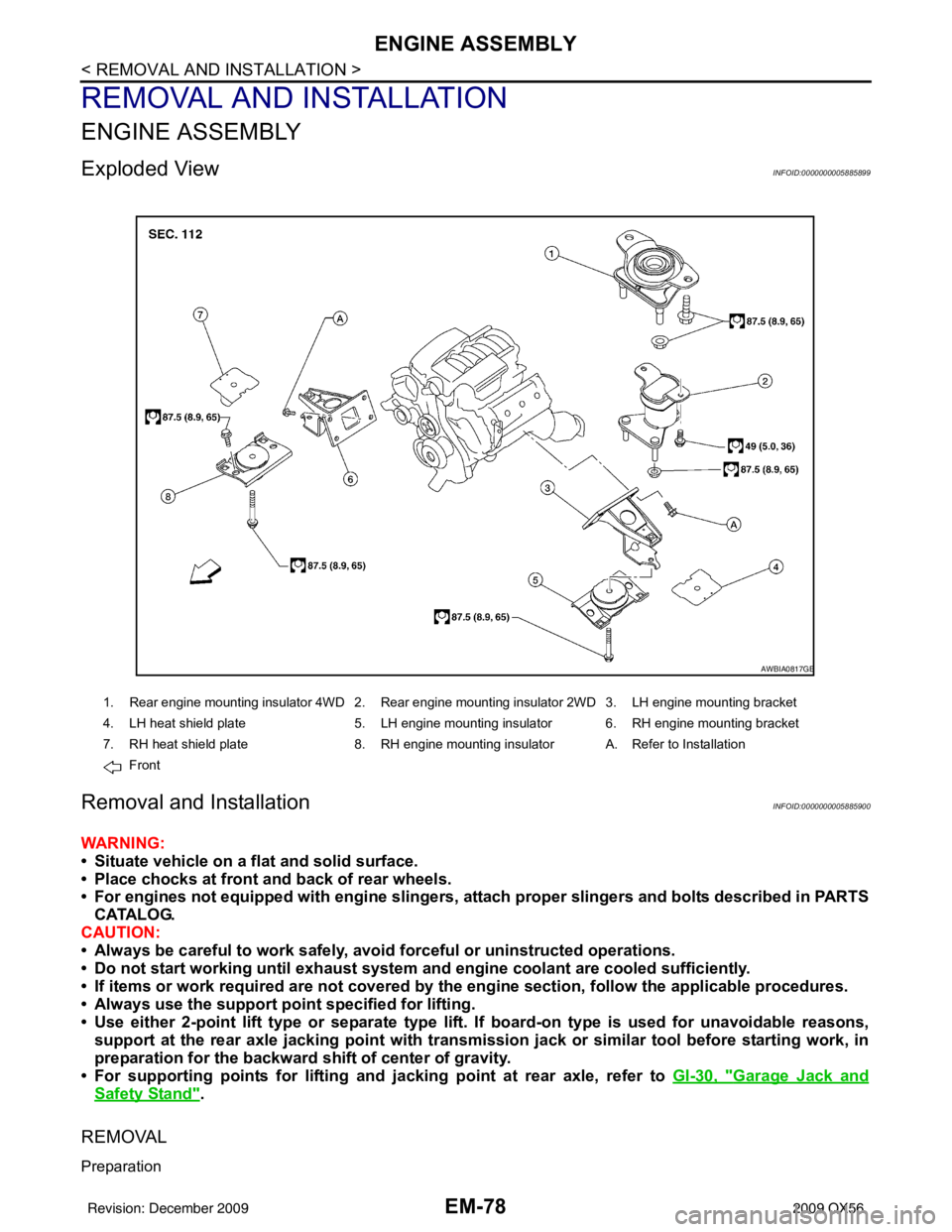
Exploded ViewINFOID:0000000005885899
Removal and InstallationINFOID:0000000005885900
WARNING:
• Situate vehicle on a flat and solid surface.
• Place chocks at front and back of rear wheels.
• For engines not equipped with engine slingers, attach proper slingers and bolts described in PARTS
CATALOG.
CAUTION:
• Always be careful to work safely, avoid forceful or uninstructed operations.
• Do not start working until exh aust system and engine coolant are cooled sufficiently.
• If items or work required are no t covered by the engine section, follow the applicable procedures.
• Always use the support poin t specified for lifting.
• Use either 2-point lift type or separate type lift. If board-on type is used for unavoidable reasons, support at the rear axle jacking point with transmission jack or similar tool before starting work, in
preparation for the backward shift of center of gravity.
• For supporting points for lifting and jacking point at rear axle, refer to GI-30, "
Garage Jack and
Safety Stand".
REMOVAL
Preparation
1. Rear engine mounting insulator 4WD 2. Rear engine mounting insulator 2WD 3. LH engine mounting bracket
4. LH heat shield plate 5. LH engine mounting insulator 6. RH engine mounting bracket
7. RH heat shield plate 8. RH engine mounting insulator A. Refer to Installation
Front
AWBIA0817GB
Revision: December 20092009 QX56
Page 1909 of 4171

EM-86
< DISASSEMBLY AND ASSEMBLY >
ENGINE UNIT
ASSEMBLY
1. Fully air-blow the coolant and oil passages in the cylinder block, cylinder bore, and crankcase to removeany foreign material.
WARNING:
Use goggles to protect your eyes.
2. Install each plug to the cylinder block (only screw-type plugs are shown).
• Apply liquid gasket. Use Genuine Thread Sealant or equivalent. Refer to GI-15,
"Recommended Chemical Products and Sealants".
• Replace copper washers with new ones.
• Tighten each plug as specified below.
3. Install main bearings and thrust bearings.
a. Remove any dust, dirt, and oil on the bearing mating surfaces of the cylinder block and main bearing caps.
b. Install thrust bearings to both sides of the No. 3 journal housing on the cylinder block and main bearing caps
• Install thrust bearings with the oil groove facing the crankshaft
arm (outside).
• Install thrust bearings with a protrusion in the center on the
main bearing caps.
c. Install main bearings paying attention to the direction. • Install the one with oil holes onto the cylinder block and theone without oil holes onto the main bearing cap.
• Before installing bearings, apply engine oil to bearing surface
(inside). Do not apply oil to the back surface, but thoroughly
clean it.
• When installing, align the bearing stopper to the notch.
• Ensure the oil holes on the cylinder block and those on the
corresponding bearing are aligned.
4. Install pilot converter to the crankshaft using suitable tool.
5. Install crankshaft to the cylinder block. • While turning crankshaft by hand, make sure it turns smoothly.
Part Washer Tightening torque
A Yes 53.9 N·m (5.5 kg-m, 40 ft-lb)
B No 19.6 N·m (2.0 kg-m, 15 ft-lb)
C Yes 62.7 N·m (6.4 kg-m, 46 ft-lb)
D Yes 62.7 N·m (6.4 kg-m, 46 ft-lb)
WBIA0419E
PBIC0093E
PBIC0094E
EMP0569D
Revision: December 20092009 QX56
Page 1943 of 4171
EX-2
< PRECAUTION >
PRECAUTIONS
PRECAUTION
PRECAUTIONS
Precaution for Supplemental Restraint System (SRS) "AIR BAG" and "SEAT BELT
PRE-TENSIONER"
INFOID:0000000005851832
The Supplemental Restraint System such as “A IR BAG” and “SEAT BELT PRE-TENSIONER”, used along
with a front seat belt, helps to reduce the risk or severity of injury to the driver and front passenger for certain
types of collision. This system includes seat belt switch inputs and dual stage front air bag modules. The SRS
system uses the seat belt switches to determine the front air bag deployment, and may only deploy one front
air bag, depending on the severity of a collision and w hether the front occupants are belted or unbelted.
Information necessary to service the system safely is included in the SR and SB section of this Service Man-
ual.
WARNING:
• To avoid rendering the SRS inopera tive, which could increase the risk of personal injury or death in
the event of a collision which would result in air bag inflation, all maintenance must be performed by
an authorized NISSAN/INFINITI dealer.
• Improper maintenance, including in correct removal and installation of the SRS, can lead to personal
injury caused by unintent ional activation of the system. For re moval of Spiral Cable and Air Bag
Module, see the SR section.
• Do not use electrical test equipmen t on any circuit related to the SRS unless instructed to in this
Service Manual. SRS wiring harn esses can be identified by yellow and/or orange harnesses or har-
ness connectors.
PRECAUTIONS WHEN USING POWER TOOLS (AIR OR ELECTRIC) AND HAMMERS
WARNING:
• When working near the Airbag Diagnosis Sensor Unit or other Airbag System sensors with the Igni-
tion ON or engine running, DO NOT use air or electri c power tools or strike near the sensor(s) with a
hammer. Heavy vibration could activate the sensor( s) and deploy the air bag(s), possibly causing
serious injury.
• When using air or electric power tools or hammers , always switch the Ignition OFF, disconnect the
battery, and wait at least 3 minu tes before performing any service.
Precaution Necessary for Steering W heel Rotation After Battery Disconnect
INFOID:0000000005851833
NOTE:
• This Procedure is applied only to models with Intelligent Key system and NATS (NISSAN ANTI-THEFT SYS-
TEM).
• Remove and install all control units after disconnecting both battery cables with the ignition knob in the
″LOCK ″ position.
• Always use CONSULT-III to perform self-diagnosis as a part of each function inspection after finishing work.
If DTC is detected, perform trouble diagnosis according to self-diagnostic results.
For models equipped with the Intelligent Key system and NATS, an electrically controlled steering lock mech-
anism is adopted on the key cylinder.
For this reason, if the battery is disconnected or if the battery is discharged, the steering wheel will lock and
steering wheel rotation will become impossible.
If steering wheel rotation is required when battery pow er is interrupted, follow the procedure below before
starting the repair operation.
OPERATION PROCEDURE
1. Connect both battery cables. NOTE:
Supply power using jumper cables if battery is discharged.
2. Use the Intelligent Key or mechanical key to turn the ignition switch to the ″ACC ″ position. At this time, the
steering lock will be released.
3. Disconnect both battery cables. The steering lock will remain released and the steering wheel can be rotated.
4. Perform the necessary repair operation.
Revision: December 20092009 QX56
Page 1947 of 4171

EX-6
< ON-VEHICLE REPAIR >
EXHAUST SYSTEM
ON-VEHICLE REPAIR
EXHAUST SYSTEM
Exploded ViewINFOID:0000000004140300
Exhaust System
Removal and InstallationINFOID:0000000003771782
WARNING:
• Perform the operation with the exhaust system fully cooled. The system will be hot just after the
engine stops.
• Be careful not to cut your hand on the heat insulator edge.
CAUTION:
• Be sure to use genuine exhaust system parts or equivalents which are specially designed for heat
resistance, corrosion resistance, and shape.
REMOVAL
Remove exhaust system components using power tool.
• Remove heated oxygen sensor using Tool as needed.
INSTALLATION
Installation is in the reverse order of removal.
CAUTION:
• Always replace exhaust gaskets with new ones when reassembling.
AWBIA0667GB
1. Tailpipe hanger bracket 2. Tailpipe3. Gasket
4. Main muffler 5. Right front exhaust tube6. Ring gasket
7. Heated oxygen sensor 2 (bank 2) 8. Heated oxygen sensor 2 (bank 1) 9. Left front exhaust tube
10. Center exhaust tube 11. Muffler hanger bracket front 12. Muffler hanger bracket rear
Front
Tool number KV10114400 (J-38365)
Revision: December 20092009 QX56
Page 1949 of 4171
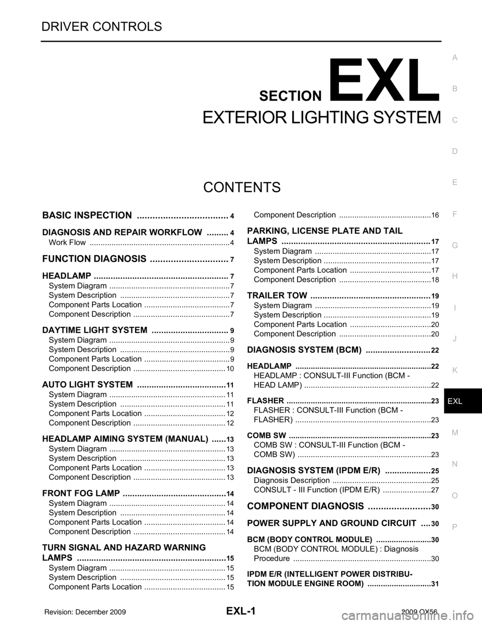
EXL-1
DRIVER CONTROLS
C
DE
F
G H
I
J
K
M
SECTION EXL
A
B
EXL
N
O P
CONTENTS
EXTERIOR LIGHTING SYSTEM
BASIC INSPECTION ....... .............................4
DIAGNOSIS AND REPAIR WORKFLOW ..... .....4
Work Flow ........................................................... ......4
FUNCTION DIAGNOSIS ...............................7
HEADLAMP .................................................... .....7
System Diagram .................................................. ......7
System Description ...................................................7
Component Parts Location ........................................7
Component Description .............................................7
DAYTIME LIGHT SYSTEM .................................9
System Diagram .................................................. ......9
System Description ...................................................9
Component Parts Location ........................................9
Component Description ...........................................10
AUTO LIGHT SYSTEM ......................................11
System Diagram ......................................................11
System Description .................................................11
Component Parts Location ......................................12
Component Description ...........................................12
HEADLAMP AIMING SYSTEM (MANUAL) .......13
System Diagram .................................................. ....13
System Description .................................................13
Component Parts Location ......................................13
Component Description ...........................................13
FRONT FOG LAMP ............................................14
System Diagram .................................................. ....14
System Description .................................................14
Component Parts Location ......................................14
Component Description ...........................................14
TURN SIGNAL AND HAZARD WARNING
LAMPS ...............................................................
15
System Diagram .................................................. ....15
System Description .................................................15
Component Parts Location ......................................15
Component Description ....................................... ....16
PARKING, LICENSE PLATE AND TAIL
LAMPS ..............................................................
17
System Diagram ......................................................17
System Description ..................................................17
Component Parts Location ......................................17
Component Description ...........................................18
TRAILER TOW ..................................................19
System Diagram ......................................................19
System Description ..................................................19
Component Parts Location ......................................20
Component Description ...........................................20
DIAGNOSIS SYSTEM (BCM) ...........................22
HEADLAMP ........................................................... ....22
HEADLAMP : CONSULT-III Function (BCM -
HEAD LAMP) ...........................................................
22
FLASHER ............................................................... ....23
FLASHER : CONSULT-III Function (BCM -
FLASHER) ...............................................................
23
COMB SW .............................................................. ....23
COMB SW : CONSULT-III Function (BCM -
COMB SW) ..............................................................
23
DIAGNOSIS SYSTEM (IPDM E/R) ...................25
Diagnosis Description ..............................................25
CONSULT - III Function (IPDM E/R) .......................27
COMPONENT DIAGNOSIS .........................30
POWER SUPPLY AND GROUND CIRCUIT ....30
BCM (BODY CONTROL MODULE) ...................... ....30
BCM (BODY CONTROL MODULE) : Diagnosis
Procedure ............................................................ ....
30
IPDM E/R (INTELLIGENT POWER DISTRIBU-
TION MODULE ENGINE ROOM) .......................... ....
31
Revision: December 20092009 QX56