mirror INFINITI QX56 2009 Factory Service Manual
[x] Cancel search | Manufacturer: INFINITI, Model Year: 2009, Model line: QX56, Model: INFINITI QX56 2009Pages: 4171, PDF Size: 84.65 MB
Page 1 of 4171
A
B
C
D
E
F
G
H
I
J
K
L
M
N
P
O
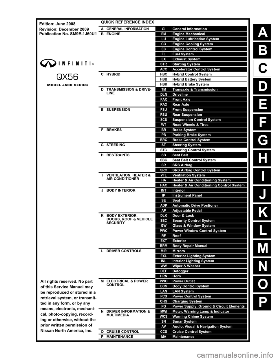
QUICK REFERENCE INDEX
AGENERAL INFORMATIONGIGeneral Information
BENGINEEMEngine Mechanical
LUEngine Lubrication System
COEngine Cooling System
ECEngine Control System
FLFuel System
EXExhaust System
STRStarting System
ACCAccelerator Control System
CHYBRIDHBCHybrid Control System
HBBHybrid Battery System
HBRHybrid Brake System
DTRANSMISSION & DRIVE-
LINETMTransaxle & Transmission
DLNDriveline
FAXFront Axle
RAXRear Axle
ESUSPENSIONFSUFront Suspension
RSURear Suspension
SCSSuspension Control System
WTRoad Wheels & Tires
FBRAKESBRBrake System
PBParking Brake System
BRCBrake Control System
GSTEERINGSTSteering System
STCSteering Control System
HRESTRAINTSSBSeat Belt
SBCSeat Belt Control System
SRSRS Airbag
SRCSRS Airbag Control System
IVENTILATION, HEATER &
AIR CONDITIONERVTLVentilation System
HAHeater & Air Conditioning System
HACHeater & Air Conditioning Control System
JBODY INTERIORINTInterior
IPInstrument Panel
SESeat
ADPAutomatic Drive Postioner
APAdjustable Pedal
KBODY EXTERIOR,
DOORS, ROOF & VEHICLE
SECURITYDLKDoor & Lock
SECSecurity Control System
GWGlass & Window System
PWCPower Window Control System
RFRoof
EXTExterior
BRMBody Repair Manual
LDRIVER CONTROLSMIRMirrors
EXLExterior Lighting System
INLInterior Lighting System
WWWiper & Washer
DEFDefogger
HRNHorn
MELECTRICAL & POWER
CONTROLPWOPower Outlet
BCSBody Control System
LANLAN System
PCSPower Control System
CHGCharging System
PGPower Supply, Ground & Circuit Elements
NDRIVER INFORMATION &
MULTIMEDIAMWIMeter, Warning Lamp & Indicator
WCSWarning Chime System
SNSonar System
AVAudio, Visual & Navigation System
OCRUISE CONTROLCCSCruise Control System
PMAINTENANCEMAMaintenance
All rights reserved. No part
of this Service Manual may
be reproduced or stored in a
retrieval system, or transmit-
ted in any form, or by any
means, electronic, mechani-
cal, photo-copying, record-
ing or otherwise, without the
prior written permission of
Nissan North America, Inc.
Edition: June 2008
Revision: December 2009
Publication No. SM9
E-1J60U1
Page 16 of 4171

ADP-2
DTC Logic ...............................................................35
Diagnosis Procedure .............................................35
B2117 ADJ PEDAL MOTOR .............................36
Description ........................................................... ...36
DTC Logic ...............................................................36
Diagnosis Procedure .............................................36
B2118 TILT SENSOR ........................................38
Description ........................................................... ...38
DTC Logic ...............................................................38
Diagnosis Procedure .............................................38
B2120 ADJ PEDAL SENSOR ...........................40
Description ........................................................... ...40
DTC Logic ...............................................................40
Diagnosis Procedure .............................................40
B2126 DETENT SW ...........................................42
Description ........................................................... ...42
DTC Logic ...............................................................42
Diagnosis Procedure .............................................42
B2128 UART COMMUNICATION LINE ............44
Description ........................................................... ...44
DTC Logic ...............................................................44
Diagnosis Procedure .............................................44
POWER SUPPLY AND GROUND CIRCUIT .....46
BCM ........................................................................ ...46
BCM : Diagnosis Procedure ...................................46
DRIVER SEAT CONTROL UNIT ........................... ...46
DRIVER SEAT CONTROL UNIT :
Diagnosis Procedure .............................................
47
DRIVER SEAT CONTROL UNIT : Special Repair
Requirement ........................................................ ...
47
AUTOMATIC DRIVE POSITIONER CONTROL
UNIT ....................................................................... ...
47
AUTOMATIC DRIVE POSITIONER CONTROL
UNIT : Diagnosis Procedure ..................................
47
AUTOMATIC DRIVE POSITIONER CONTROL
UNIT : Special Repair Requirement .......................
48
SLIDING SWITCH ..............................................49
Description ........................................................... ...49
Component Function Check .................................49
Diagnosis Procedure .............................................49
Component Inspection ............................................50
RECLINING SWITCH ........................................51
Description ........................................................... ...51
Component Function Check .................................51
Diagnosis Procedure .............................................51
Component Inspection ............................................52
LIFTING SWITCH (FRONT) ..............................53
Description ........................................................... ...53
Component Function Check .................................53
Diagnosis Procedure .............................................53
Component Inspection ......................................... ...54
LIFTING SWITCH (REAR) ................................55
Description ........................................................... ...55
Component Function Check ..................................55
Diagnosis Procedure ..............................................55
Component Inspection ............................................56
TILT SWITCH ....................................................57
Description ........................................................... ...57
Component Function Check ..................................57
Diagnosis Procedure ..............................................57
Component Inspection ............................................58
PEDAL ADJUSTING SWITCH ..........................59
Description ........................................................... ...59
Component Function Check ..................................59
Diagnosis Procedure ..............................................59
Component Inspection ............................................61
SEAT MEMORY SWITCH .................................62
Description ........................................................... ...62
Component Function Check ..................................62
Diagnosis Procedure ..............................................62
Component Inspection ............................................63
DOOR MIRROR REMOTE CONTROL
SWITCH .............................................................
64
CHANGEOVER SWITCH ....................................... ...64
CHANGEOVER SWITCH : Description ..................64
CHANGEOVER SWITCH : Component Function
Check ......................................................................
64
CHANGEOVER SWITCH : Diagnosis Procedure ...64
CHANGEOVER SWITCH : Component Inspec-
tion ..........................................................................
65
MIRROR SWITCH .................................................. ...66
MIRROR SWITCH : Description .............................66
MIRROR SWITCH : Component Function Check ...66
MIRROR SWITCH : Diagnosis Procedure ..............66
MIRROR SWITCH : Component Inspection ...........68
POWER SEAT SWITCH GROUND CIRCUIT ...69
Diagnosis Procedure ..............................................69
DETENTION SWITCH .......................................70
Description ........................................................... ...70
Component Function Check ..................................70
Diagnosis Procedure ..............................................70
FRONT DOOR SWITCH (DRIVER SIDE) .........72
Description ........................................................... ...72
Component Function Check ...................................72
Diagnosis Procedure ...............................................72
Component Inspection ............................................72
SLIDING SENSOR ............................................74
Description ........................................................... ...74
Component Function Check ..................................74
Diagnosis Procedure ..............................................74
Revision: December 20092009 QX56
Page 17 of 4171

ADP-3
C
DE
F
G H
I
K L
M A
B
ADP
N
O P
RECLINING SENSOR .................................... ....76
Description .......................................................... ....76
Component Function Check ..................................76
Diagnosis Procedure ..............................................76
LIFTING SENSOR (FRONT) ..............................78
Description .......................................................... ....78
Component Function Check ..................................78
Diagnosis Procedure ..............................................78
LIFTING SENSOR (REAR) ................................80
Description .......................................................... ....80
Component Function Check ..................................80
Diagnosis Procedure ..............................................80
TILT SENSOR ....................................................82
Description .......................................................... ....82
Component Function Check ..................................82
Diagnosis Procedure ..............................................82
PEDAL ADJUSTING SENSOR ..........................84
Description .......................................................... ....84
Component Function Check ..................................84
Diagnosis Procedure ..............................................84
MIRROR SENSOR .............................................86
DRIVER SIDE ........................................................ ....86
DRIVER SIDE : Description ....................................86
DRIVER SIDE : Component Function Check ........86
DRIVER SIDE : Diagnosis Procedure ....................86
PASSENGER SIDE ...................................................88
PASSENGER SIDE : Description ....................... ....88
PASSENGER SIDE :
Component Function Check ..................................
88
PASSENGER SIDE : Diagnosis Procedure ...........88
SLIDING MOTOR ...............................................90
Description .......................................................... ....90
Component Function Check ..................................90
Diagnosis Procedure ..............................................90
RECLINING MOTOR ..........................................92
Description .......................................................... ....92
Component Function Check ..................................92
Diagnosis Procedure ..............................................92
LIFTING MOTOR (FRONT) ................................94
Description .......................................................... ....94
Component Function Check ..................................94
Diagnosis Procedure ..............................................94
LIFTING MOTOR (REAR) ..................................96
Description .......................................................... ....96
Component Function Check ..................................96
Diagnosis Procedure ..............................................96
TILT MOTOR ......................................................98
Description .......................................................... ....98
Component Function Check ..................................98
Diagnosis Procedure ..............................................98
PEDAL ADJUSTING MOTOR ........................100
Description ........................................................... ..100
Component Function Check ................................100
Diagnosis Procedure ............................................100
DOOR MIRROR MOTOR ................................102
Description .............................................................102
Component Function Check ..................................102
Diagnosis Procedure .............................................102
Component Inspection ...........................................104
SEAT MEMORY INDICATOR LAMP ..............105
Description .............................................................105
Component Function Check ................................105
Diagnosis Procedure ............................................105
Component Inspection ...........................................106
ECU DIAGNOSIS .......................................107
DRIVER SEAT CONTROL UNIT ....................107
Reference Value .................................................. ..107
Wiring Diagram ......................................................112
Fail Safe ................................................................126
DTC Index .............................................................127
AUTOMATIC DRIVE POSITIONER CON-
TROL UNIT ......................................................
128
Reference Value ....................................................128
Wiring Diagram ......................................................131
BCM (BODY CONTROL MODULE) ...............146
Reference Value ....................................................146
Terminal Layout .....................................................148
Physical Values .....................................................148
Wiring Diagram ......................................................154
SYMPTOM DIAGNOSIS ............................159
ADP SYSTEM SYMPTOMS ............................159
Symptom Table ................................................... ..159
NORMAL OPERATING CONDITION .............161
Description .............................................................161
PRECAUTION ............................................162
PRECAUTIONS ...............................................162
Precaution for Supplemental Restraint System
(SRS) "AIR BAG" and "SEAT BELT PRE-TEN-
SIONER" ............................................................. ..
162
Precaution Necessary for Steering Wheel Rota-
tion After Battery Disconnect .................................
162
Precaution for Work ...............................................163
PREPARATION .........................................164
PREPARATION ...............................................164
Special Service Tool ............................................ ..164
Commercial Service Tool ......................................164
ON-VEHICLE REPAIR ...............................165
Revision: December 20092009 QX56
Page 18 of 4171

ADP-4
DRIVER SEAT CONTROL UNIT .....................165
Removal and Installation ..................................... ..165
AUTOMATIC DRIVE POSITIONER CON-
TROL UNIT ......................................................
166
Removal and Installation ..................................... ..166
SEAT MEMORY SWITCH ...............................167
Removal and Installation ..................................... ..167
DOOR MIRROR REMOTE CONTROL
SWITCH ............................................................
168
Removal and Installation ...................................... .168
PEDAL ADJUSTING MOTOR ..........................169
Removal and Installation ...................................... .169
TILT SWITCH ...................................................170
Removal and Installation ...................................... .170
Revision: December 20092009 QX56
Page 23 of 4171
PRE-INSPECTION FOR DIAGNOSTICADP-9
< BASIC INSPECTION >
C
DE
F
G H
I
K L
M A
B
ADP
N
O P
PRE-INSPECTION FOR DIAGNOSTIC
Basic InspectionINFOID:0000000004055281
1. CHECK POWER SUPPLY AND DROUND CIRCUIT
Check the power supply and ground circuit as shown below.
Driver seat control unit: Refer to ADP-47, "DRIVER SEAT CONTROL UNIT : Diagnosis Procedure"
.
Automatic drive positioner control unit: Refer to ADP-47, "AUTOMATIC DRIVE POSITIONER CONTROL
UNIT : Diagnosis Procedure".
Is the inspection result normally?
YES >> GO TO 2
NO >> Repair or replace the malfunctioning part.
2. CHECK MANUAL FUNCTION
Check the manual function operati ons by operating the relevant switches as shown below.
Seat (slide, reclining, lifting front, lifting rear)
Pedal assembly (forward, backward)
Steering wheel (upward, downward)
Door mirror
Do all manual functions operate normally?
YES >> GO TO 3
NO (Seat, pedal, door mirror)>>Go to SYMPTOM 1, refer to ADP-159, "Symptom Table"
. And, GO TO 4 if
the result of SYMPTOM 1 is OK.
3. CHECK MEMORY FUNCTION 1
Register the seat positions (refer to Owner’s Manual) and check that all parts of the seat, pedals, steering
wheel and door mirrors move to their memory positions correctly.
Are the operations normal?
YES >> Check each malfunction according to the instruction of the SYMPTOM 4, refer to ADP-159,
"Symptom Table".
No (memory indicator operates normally)>> Go to SYMPTOM 2, refer to ADP-159, "Symptom Table"
.
No (memory indicator does not operate normally either)>> GO TO 5
4. CHECK MEMORY FUNCTION 2
Register the seat positions (refer to Owner’s Manual) and check that all parts of the seat, pedals, steering
wheel and door mirrors move to their memory positions correctly.
Are the operations normal?
YES >> Check intermittent incident. Refer to GI-38, "Intermittent Incident".
NO >> GO TO 7
5. CHECK SEAT MEMORY SW ITCH/MEMORY INDICATOR
Check the seat memory switch/memory switch indicator of the SYMPTOM 5, refer to ADP-159, "Symptom
Table".
Is the inspection result normal?
YES >> GO TO 6
NO >> Repair or replace the malfunctioning part.
6. CHECK OPERATION CONDITION
Check the memory operation conditions (refer to ADP-12, "AUTOMATIC DRIVE POSITIONER SYSTEM :
System Description").
Are all operation conditions fulfilled?
YES >> Go to SYMPTOM 6, refer to ADP-159, "Symptom Table".
NO >> Fulfill the operation conditions. Refer to ADP-12, "AUTOMATIC DRIVE POSITIONER SYSTEM :
System Description".
7. CHECK MECHANISM
Check for the following.
Revision: December 20092009 QX56
Page 26 of 4171
ADP-12
< FUNCTION DIAGNOSIS >
AUTOMATIC DRIVE POSITIONER SYSTEM
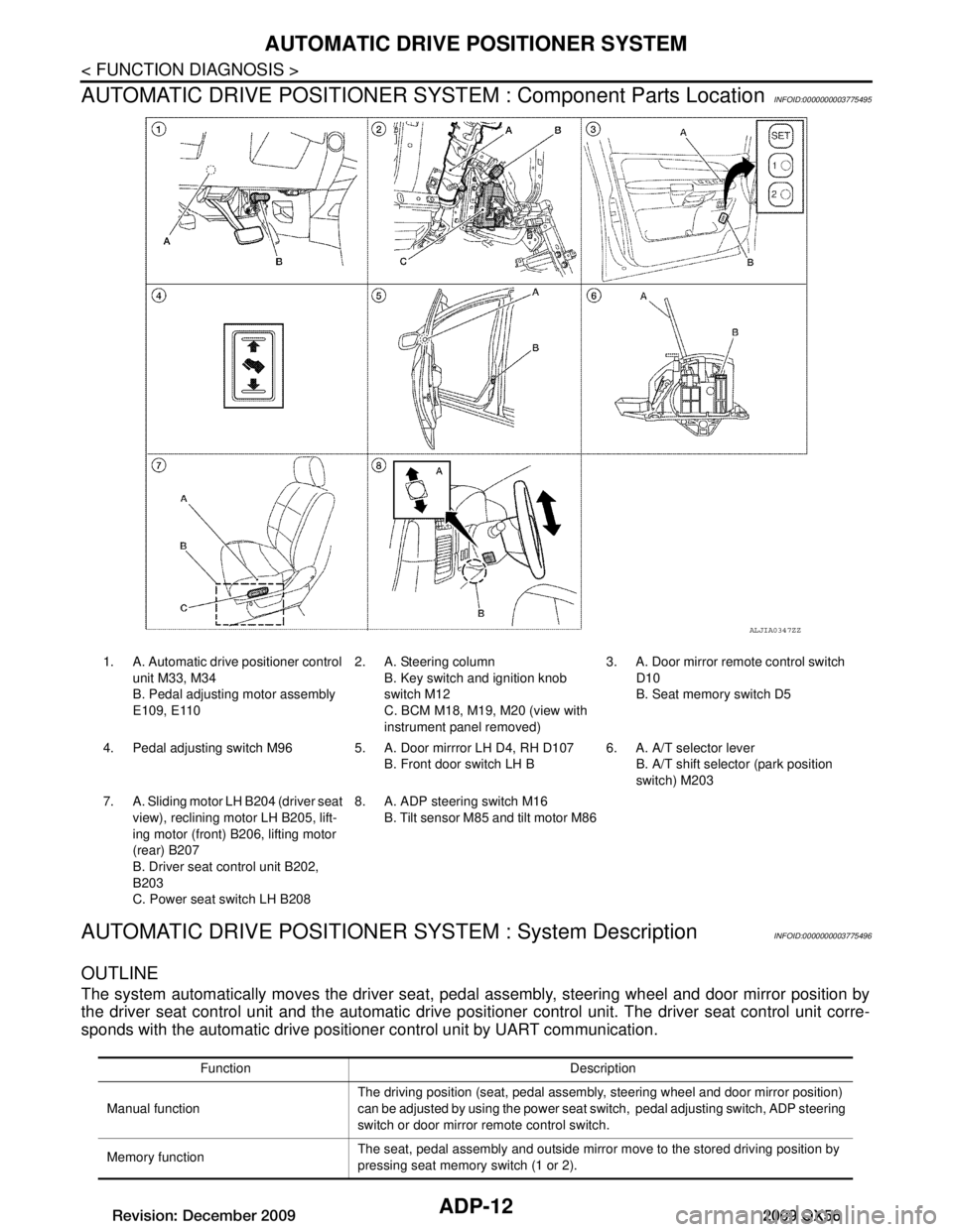
AUTOMATIC DRIVE POSITIONER SYST EM : Component Parts Location
INFOID:0000000003775495
AUTOMATIC DRIVE POSITIONER SYSTEM : System DescriptionINFOID:0000000003775496
OUTLINE
The system automatically moves the driver seat, pedal assembly, steering wheel and door mirror position by
the driver seat control unit and the automatic drive posit ioner control unit. The driver seat control unit corre-
sponds with the automatic drive positioner control unit by UART communication.
ALJIA0347ZZ
1. A. Automatic drive positioner control
unit M33, M34
B. Pedal adjustin g motor assembly
E109, E110 2. A. Steering column
B. Key switch and ignition knob
switch M12
C. BCM M18, M19, M20 (view with
instrument panel removed) 3. A. Door mirror remo
te control switch
D10
B. Seat memory switch D5
4. Pedal adjusting switch M96 5 . A. Door mirrror LH D4, RH D107
B. Front door switch LH B 6. A. A/T selector lever
B. A/T shift selector (park position
switch) M203
7. A. Sliding motor LH B204 (driver seat
view), reclining motor LH B205, lift-
ing motor (front) B2 06, lifting motor
(rear) B207
B. Driver seat control unit B202,
B203
C. Power seat switch LH B208 8. A. ADP steering switch M16
B. Tilt sensor M85 and tilt motor M86
Function Description
Manual function The driving position (seat, pedal assembly, steering wheel and door mirror position)
can be adjusted by using the power seat switch, pedal adjusting switch, ADP steering
switch or door mirror
remote control switch.
Memory function The seat, pedal assembly and outside mirror move to the stored driving position by
pressing seat memory switch (1 or 2).
Revision: December 20092009 QX56
Page 27 of 4171
AUTOMATIC DRIVE POSITIONER SYSTEMADP-13
< FUNCTION DIAGNOSIS >
C
DE
F
G H
I
K L
M A
B
ADP
N
O P
AUTOMATIC DRIVE POSITIONER SYSTEM : Component DescriptionINFOID:0000000003775497
CONTROL UNITS
INPUT PARTS
Switches
Entry/Exit assist functionExit On exit, the seat moves backward and the steering wheel moves upward.
Entry
On entry, the seat and steering wheel return from exiting position to the previous driv-
ing position.
Function Description
Item Function
Driver seat control unit Main unit of automatic drive positioner system
It is connected to the CAN.
It communicates with the automatic drive positioner control unit via UART com-
munication.
Automatic drive positioner control unit It communicates with the driver seat control unit via UART communication.
Perform various controls with the instructions of driver seat control unit.
Perform the controls of the pedal adjusting, steering wheel, door mirror and the
seat memory switch.
BCM Transmit the following status to the driver seat control unit via CAN communication.
Front door LH: OPEN/CLOSE
Ignition switch position: ACC/ON
Door lock: UNLOCK (with Intelligent Key or remote keyless entry request switch
operation)
Key ID
Key switch: Insert/Pull out Intelligent Key
Starter: CRANKING/OTHER
Combination meter Transmit the vehicle speed signal to the driver seat control unit via CAN communi-
cation.
AV control unit The setting change of auto drive positioner system can be performed on the display.
A/T shift selector (park position switch) Transmit the shift position signal (P range) to the driver seat control unit.
Item Function
Key switch and ignition knob switch The key switch is installed to detect the key inserted/removed status.
Front door switch LH Detect front door (driver side) open/close status.
A/T shift selector (park position switch) Detect the P range position of A/T selector lever.
Set switch The registration and system setting can be performed with its operation.
Seat memory switch 1/2 The registration and operation can be performed with its operation.
Power seat switch The following switch is installed.
Reclining switch
Lifting switch (front)
Lifting switch (rear)
Sliding switch
The specific parts can be operated with the operation of each switch.
Pedal adjusting switch The following switch is installed.
Pedal forward
Pedal backward
The specific parts can be operated with the operation of each switch.
Revision: December 20092009 QX56
Page 28 of 4171

ADP-14
< FUNCTION DIAGNOSIS >
AUTOMATIC DRIVE POSITIONER SYSTEM
Sensors
OUTPUT PARTS
MANUAL FUNCTION
ADP steering switchThe following switch is installed.
Steering wheel UP
Steering wheel down
The specific parts can be operated with the operation of each switch.
Door mirror remote control switch The following switch is installed.
Mirror switch
Changeover switch
The specific parts can be operated with the operation of each switch.
Item Function
Item Function
Door mirror sensor (LH/RH) Detect the up/down and left/right position of outside mirror face.
Pedal adjusting sensor Detect the forward/backward position of pedal assembly.
Tilt sensor Detect the upward/downward position of the steering wheel.
Lifting sensor (front) Detect the up/down position of seat lifting (front).
Lifting sensor (rear) Detect the up/down position of seat lifting (rear).
Reclining sensor Detect the tilt of seatback.
Sliding sensor Detect the front/rear position of seat.
Item Function
Door mirror motor (LH/RH) Move the outside mirror face upward/downward and left/right.
Pedal adjusting motor Move the pedal assembly forward/backward.
Tilt motor Move the steering wheel upward/downward.
Lifting motor (front) Move the seat lifting (front) upward/downward.
Lifting motor (rear) Move the seat lifting (rear) upward/downward.
Reclining motor Tilt and raise up the seatback.
Sliding motor Slide the seat forward/backward.
Seat memory indicator Illuminates or flashes according to the registration/operation status.
Revision: December 20092009 QX56
Page 29 of 4171
AUTOMATIC DRIVE POSITIONER SYSTEMADP-15
< FUNCTION DIAGNOSIS >
C
DE
F
G H
I
K L
M A
B
ADP
N
O P
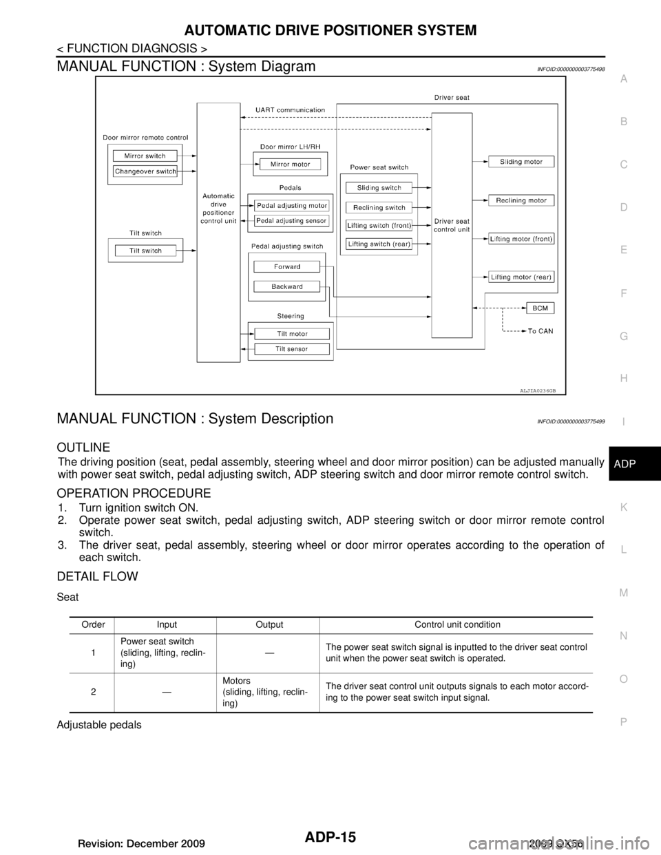
MANUAL FUNCTION : System DiagramINFOID:0000000003775498
MANUAL FUNCTION : System DescriptionINFOID:0000000003775499
OUTLINE
The driving position (seat, pedal assembly, steering wheel and door mirror position) can be adjusted manually
with power seat switch, pedal adjusting switch, ADP st eering switch and door mirror remote control switch.
OPERATION PROCEDURE
1. Turn ignition switch ON.
2. Operate power seat switch, pedal adjusting switch, ADP steering switch or door mirror remote control
switch.
3. The driver seat, pedal assembly, steering wheel or door mirror operates according to the operation of each switch.
DETAIL FLOW
Seat
Adjustable pedals
ALJIA0236GB
Order Input Output Control unit condition
1 Power seat switch
(sliding, lifting, reclin-
ing)
—
The power seat switch signal is inputted to the driver seat control
unit when the power seat switch is operated.
2— Motors
(sliding, lifting, reclin-
ing)The driver seat control unit outputs signals to each motor accord-
ing to the power seat switch input signal.
Revision: December 20092009 QX56
Page 30 of 4171

ADP-16
< FUNCTION DIAGNOSIS >
AUTOMATIC DRIVE POSITIONER SYSTEM
Tilt steering wheel
Door Mirror
NOTE:
The door mirrors can be operated manually when ignition switch is in either ACC or ON position. The ignition
switch signal (ACC/ON) is transmitted from BCM to t he driver seat control unit via CAN communication and
from the driver seat control unit to the automatic drive positioner control unit via UART communication.
Order Input Output Control unit condition
1 Pedal adjusting switch — The pedal adjusting switch signal is input to the automatic drive
positioner control unit when the pedal adjusting switch is operat-
ed.
2—Motor The automatic drive positioner control unit actuates the motor ac-
cording to the operation of the pedal adjusting switch signal from
the driver seat control unit.
3 Sensor
(forward, backward) —The automatic drive positioner control unit recognizes any oper-
ation limit of each actuator via each sensor and will not operate
the actuator anymore at that time.
Order Input Output Control unit condition
1 ADP steering switch — The ADP steering switch signal is input to the automatic drive po-
sitioner control unit when the ADP steering switch is operated.
2—Motor The automatic drive positioner control unit actuates the tilt motor
according to the operation of the ADP steering switch signal.
3 Sensor
(upward, downward) —The automatic drive positioner control unit recognizes any oper-
ation limit of each actuator via each sensor and will not operate
the actuator anymore at that time.
Order Input Output Control unit condition
1 Door mirror remote
control switch —The door mirror remote control switch signal is inputted to the au-
tomatic drive positioner control unit when the door mirror remote
control switch is operated.
2— Motors
(Door mirror motor)The automatic drive positioner control unit actuates each motor
according to the operation of the door mirror remote control switch.
Revision: December 20092009 QX56