air bleeding INFINITI QX56 2009 Factory User Guide
[x] Cancel search | Manufacturer: INFINITI, Model Year: 2009, Model line: QX56, Model: INFINITI QX56 2009Pages: 4171, PDF Size: 84.65 MB
Page 3608 of 4171

POWER STEERING OIL PUMPST-17
< ON-VEHICLE REPAIR >
C
DE
F
H I
J
K L
M A
B
ST
N
O P
POWER STEERING OIL PUMP
On-Vehicle Inspection and ServiceINFOID:0000000004187603
CHECKING RELIEF OIL PRESSURE
CAUTION:
Before starting work, confirm belt tension is proper.
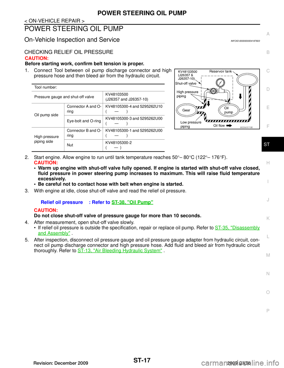
1. Connect Tool between oil pump discharge connector and high pressure hose and then bleed air from the hydraulic circuit.
2. Start engine. Allow engine to run until tank temperature reaches 50 °– 80 °C (122 °– 176 °F).
CAUTION:
Warm up engine with shut-off valve fully opened. If engine is started with shut-off valve closed,
fluid pressure in power steering pump increases to maximum. This will raise fluid temperature
excessively.
Be careful not to contact hose with belt when engine is started.
3. With engine at idle, close shut-off valve and read the relief oil pressure.
CAUTION:
Do not close shut-off valve of pressu re gauge for more than 10 seconds.
4. After measurement, open shut-off valve slowly. If relief oil pressure is outside the specific ation, repair or replace oil pump. Refer to ST-35, "Disassembly
and Assembly" .
5. After inspection, disconnect oil pressure gauge and oil pressure gauge adapter from hydraulic circuit, con-
nect oil pump discharge connector and high pressure hose. Add fluid and bleed air from hydraulic circuit
thoroughly. Refer to ST-13, "Air Bleeding Hydraulic System"
.
Tool number:
Pressure gauge and shut-off valve KV48103500
(J26357 and J26357-10)
Oil pump side Connector A and O-
ring
KV48105300-4 and 5295262U10
(—)
Eye-bolt and O-ring KV48105300-3 and 5295262U00
(—)
High pressure
piping side Connector B and O-
ring
KV48105300-1 and 5295262U00
(—)
Nut KV48105300-2
( — )
SGIA0570E
Relief oil pressure : Refer to
ST-38, "Oil Pump"
Revision: December 20092009 QX56
Page 3616 of 4171

POWER STEERING GEAR AND LINKAGEST-25
< REMOVAL AND INSTALLATION >
C
DE
F
H I
J
K L
M A
B
ST
N
O P
With steering wheel in straight ahead position, make sure slit of lower joint "A" fits with the projection on rear cover cap "B", while
checking that mark on steering gear assembly aligns with mark on
rear cover cap
After installation, bleed the air from the steering hydraulic system. Refer to ST-13, "Air Bleeding Hydraulic
System".
INSPECTION AFTER INSTALLATION
Check if steering wheel turns smoothly when it is turned several times fully to the left and right lock positions.
SST491C
Revision: December 20092009 QX56
Page 3617 of 4171

ST-26
< REMOVAL AND INSTALLATION >
POWER STEERING OIL PUMP
POWER STEERING OIL PUMP
Removal and InstallationINFOID:0000000004187597
REMOVAL
1. Drain power steering fluid from reservoir tank.
2. Remove engine room cover. Refer to EM-24, "Removal and Installation"
.
3. Remove air duct assembly. Refer to EM-25, "Removal and Installation"
.
4. Remove power steering reservoir tank.
5. Remove serpentine drive belt belt from auto tensioner and power steering pump. Refer to EM-13,
"Removal and Installation".
6. Disconnect pressure sensor electrical connector.
7. Remove high pressure and low pressure piping from power steering oil pump. Refer to ST-27
.
8. Remove bolts, then remove power steering pump.
INSTALLATION
Installation is in the reverse order of removal. Refer to ST-27 for tightening torque.
After installation, bleed air. Refer to ST-13, "Air Bleeding Hydraulic System"
.
NOTE:
Belt tension is automatic and requires no adjustment.
Revision: December 20092009 QX56