automatic transmission INFINITI QX56 2009 Factory User Guide
[x] Cancel search | Manufacturer: INFINITI, Model Year: 2009, Model line: QX56, Model: INFINITI QX56 2009Pages: 4171, PDF Size: 84.65 MB
Page 2684 of 4171

PERIODIC MAINTENANCEMA-11
< ON-VEHICLE MAINTENANCE >
C
DE
F
G H
I
J
K L
M B
MA
N
O A
Abbreviations: R = Replace. I = Inspec
t. Correct or replace if necessary.
(1) Using automatic transmission fluid other th an Genuine NISSAN Matic S ATF or Matic J ATF will cause deterioration in drive-
ability and automatic transmission durability, and may damage the automatic transmission, which is not covered by the
INFINITI new vehicle limited warranty.
(2) Refer to “Tire rotation” under the “General maintenance” heading earlier in this section.
MAINTENANCE OPERATION
MAINTENANCE INTERVALReference
Section
- Page or
- Content
Title
Perform at number of miles, kilometers or
months, whichever comes first.
Miles x 1,000
(km x 1,000)
Months 7.5
(12)
6 15
(24)
12 22.5
(36)
18 30
(48)
24 37.5
(60)
30 45
(72)
36 52.
5
(84) 42 60
(96)
48
Brake lines and cables IIIIMA-30
Brake pads and rotors IIIIMA-30
Automatic transmission fluid, transfer fluid
and differential gear oil N
O TE (1)IIII MA-23
,
MA-25
,
MA-26
,
MA-27
Steering gear and linkage, axle and suspen-
sion parts II
MA-31,
MA-32
Tire rotation NOTE (2) MA-29
Drive shaft boots and propeller shaft
(4WD)IIII
MA-26
Exhaust system IIMA-22
In-cabin microfilter RRRRMA-22
Revision: December 20092009 QX56
Page 2685 of 4171

MA-12
< ON-VEHICLE MAINTENANCE >
RECOMMENDED FLUIDS AND LUBRICANTS
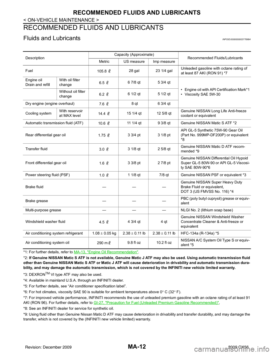
RECOMMENDED FLUIDS AND LUBRICANTS
Fluids and LubricantsINFOID:0000000003776984
*1: For further details, refer to MA-13, "Engine Oil Recommendation".
*2: If Genuine NISSAN Matic S ATF is not available, Genuine Matic J ATF may also be used. Using automatic transmission fluid
other than Genuine NISSAN Matic S ATF or Matic J ATF will cause deterioration in drivability and automatic transmission dura-
bility, and may damage the automatic transmission, which is not covered by the INFINITI new vehicle limited warranty.
*3: DEXRON
TM VI type ATF may also be used.
*4: Available in mainland U.S.A. through an INFINITI dealer.
*5: For further details, see “Air conditioner specification label”.
*6: For hot climates, viscosity SAE 90 is suitable for ambient te mperatures above 0° C (32 ° F).
*7: For improved vehicle performance, INFINITI recommends the use of unleaded premium gasoline with an octane rating of at leas t 91
AKI (RON 96). For further details, refer to GI-27, "
Precaution for Fuel (Unleaded Premium Gasoline Recommended)",
*8: See an INFINITI dealer for service for synthetic oil.
*9: Using fluid other than Genuine Nissan Matic D ATF may cause deterioration in drivability and transfer durability, and may d amage the
transfer, which is not covered by the (INFINITI new vehicle limited) warranty. Description
Capacity (Approximate)
Recommended Fluids/Lubricants
Metric US measure Imp measure
Fuel 105.8 28 gal 23 1/4 gal Unleaded gasoline with octane rating of
at least 87 AKI (RON 91) *7
Engine oil
Drain and refill With oil filter
change
6.5
6 7/8 qt 5 3/4 qt
• Engine oil with API Certification Mark*1
• Viscosity SAE 5W-30
Without oil filter
change
6.2
6 1/2 qt 5 1/2 qt
Dry engine (engine overhaul) 7.6 8 qt
6 3/4 qt
Cooling system With reservoir
at MAX level
14.4
15 1/4 qt 12 5/8 qt Genuine NISSAN Long Life Anti-freeze
coolant or equivalent
Automatic transmission fluid (ATF) 10.6 11 1/4 qt 9 3/8 qt Genuine NISSAN Matic S ATF *2
Rear differential gear oil 1.75 3 3/4 pt 3 1/8 pt API GL-5 Synthetic 75W-90 Gear Oil
(Part No. 999MP-DF200P) or equivalent
*8
Transfer fluid 3.0 3 1/8 qt 2 5/8 qt Genuine NISSAN Matic D ATF recom-
mended *9
Front differential gear oil 1.6 3 3/8 pt 2 7/8 pt Genuine NISSAN Differential Oil Hypoid
Super GL-5 80W-90 or API GL-5 Viscosi-
ty SAE 80W-90*6
Power steering fluid (PSF) 1.0 1 1/8 qt 7/8 qt Genuine NISSAN PSF or equivalent *3
Brake fluid —— —Genuine NISSAN Super Heavy Duty
Brake Fluid or equivalent,
DOT 3 (US FMVSS No. 116) *4
Brake grease —— —PBC (poly butyl cuprysil) grease or equiv-
alent
Multi-purpose grease —— — NLGI No. 2 (lithium soap base)
Windshield washer fluid 4.5 4 3/4 qt
4 qtGenuine NISSAN Windshield Washer
Concentrate Cleaner & Anti-freeze or
equivalent
Air conditioning system refrigerant 1.08 ± 0.05 kg 2.38 ± 0.11 lb 2.38 ± 0.11 lb HFC-134a (R-134a) *5
Air conditioning system oil 290 m9.8 fl oz 10.2 fl oz NISSAN A/C System Oil Type S or equiv-
alent *5
Revision: December 20092009 QX56
Page 3657 of 4171

A/T CONTROL SYSTEMTM-9
< FUNCTION DIAGNOSIS >
CEF
G H
I
J
K L
M A
B
TM
N
O P
Cross-Sectional View (4WD models)INFOID:0000000003771806
Shift MechanismINFOID:0000000003771807
The automatic transmission uses compact triple planet ary gear systems to improve power-transmission effi-
ciency, simplify construction and reduce weight.
It also employs an optimum shift control and super wide gear ratios. They improve starting performance and
acceleration during medium and high-speed operation.
CONSTRUCTION
1. Front planetary gear 2. Mid planetary gear 3. Rear planetary gear
4. Direct clutch 5. High and low reverse clutch 6. Reverse brake
7. Drum support 8. Forward brake 9. Low coast brake
10. Input shaft 11. Torque converter 12. Oil pump
13. Front brake 14. 3rd one-way clutch 15. Input clutch
16. 1st one-way clutch 17. Control valve with TCM 18. Forward one-way clutch
19. Adapter case 20. Output shaft
SCIA5268E
Revision: December 20092009 QX56
Page 3659 of 4171

A/T CONTROL SYSTEMTM-11
< FUNCTION DIAGNOSIS >
CEF
G H
I
J
K L
M A
B
TM
N
O P
—Operates
—Operates during “pro gressive” acceleration.
—Operates and effects power transmission while coasting.
—Line pressure is applied but does not affect power transmission.
—Operates under conditions shown in HLR/C Operating Condition
—Operates under conditions shown in LC/B Operating Condition. Delay control is applied during D (4,3,2,1) ⇒N shift.
POWER TRANSMISSION
“N” Position
N NEUTRAL POSI-
TION
D 1st
Automatic shift
1 ⇔ 2⇔ 3⇔ 4⇔ 5
2nd
3rd
4th
5th1st
4 2nd
Automatic shift
3rd 1
⇔ 2⇔ 3⇔ 4
4th
3 1st
Automatic shift1⇔ 2⇔ 3⇐ 4
2nd
3rd 4th
2 1st
Automatic shift1⇔ 2⇐ 3⇐ 4
2nd
3rd
4th
1 1st
Locks (held sta-tionary in 1st gear)
1 ⇐ 2⇐ 3⇐ 4
2nd
3rd4th
Shift position I/C HLR/C D/C R/B FR/B LC/B Fwd/B
1st
OWC Fwd
OWC 3rd
OWC Remarks
SCIA5642E
Revision: December 20092009 QX56
Page 3668 of 4171

TM-20
< FUNCTION DIAGNOSIS >
A/T CONTROL SYSTEM
TCM Function
INFOID:0000000003771808
The function of the TCM is to:
Receive input signals sent from various switches and sensors.
Determine required line pressure, shifting poi nt, lock-up operation, and engine brake operation.
Send required output signals to the respective solenoids.
CONTROL SYSTEM OUTLINE
The automatic transmission senses v ehicle operating conditions through vari ous sensors or signals. It always
controls the optimum shift position and reduces shifting and lock-up shocks.
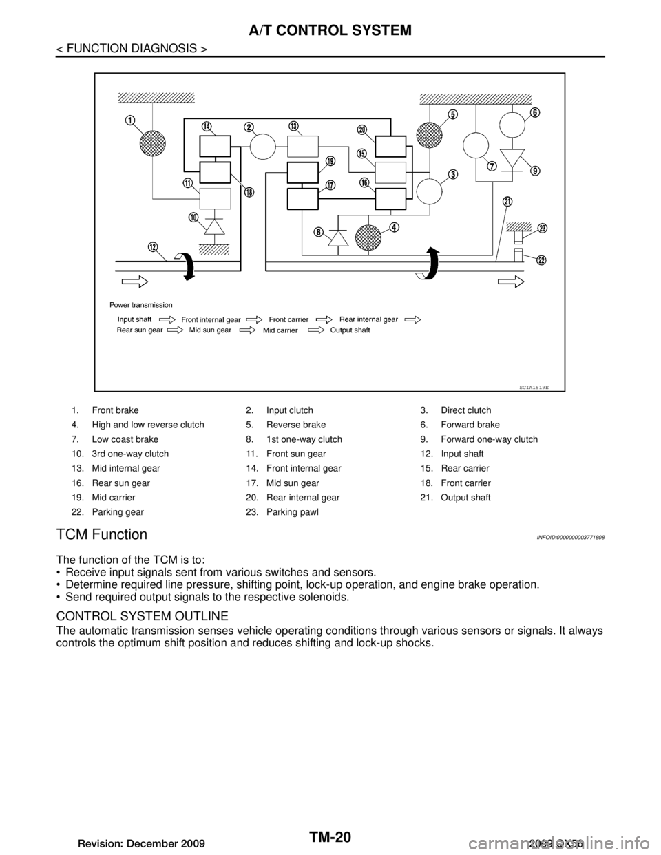
1. Front brake 2. Input clutch 3. Direct clutch
4. High and low reverse clutch 5. Reverse brake 6. Forward brake
7. Low coast brake 8. 1st one-way clutch 9. Forward one-way clutch
10. 3rd one-way clutch 11. Front sun gear 12. Input shaft
13. Mid internal gear 14. Front internal gear 15. Rear carrier
16. Rear sun gear 17. Mid sun gear 18. Front carrier
19. Mid carrier 20. Rear internal gear 21. Output shaft
22. Parking gear 23. Parking pawl
SCIA1519E
Revision: December 20092009 QX56
Page 3678 of 4171

TM-30
< FUNCTION DIAGNOSIS >
ON BOARD DIAGNOSTIC (OBD) SYSTEM
ON BOARD DIAGNOSTIC (OBD) SYSTEM
IntroductionINFOID:0000000003771819
The A/T system has two self-diagnostic systems.
The first is the emission-related on board diagnostic syst em (OBD-II) performed by the TCM in combination
with the ECM. The malfunction is indicated by the MI L (malfunction indicator lamp) and is stored as a DTC in
the ECM memory but not the TCM memory.
The second is the TCM original self-diagnosis indicat ed by the A/T CHECK indicator lamp. The malfunction is
stored in the TCM memory. The detected items are ov erlapped with OBD-II self-diagnostic items. For detail,
refer to TM-32, "CONSULT-III Function (TRANSMISSION)"
.
OBD-II Function for A/T SystemINFOID:0000000003771820
The ECM provides emission-related on board diagnostic (O BD-II) functions for the A/T system. One function
is to receive a signal from the TCM used with OBD-relat ed parts of the A/T system. The signal is sent to the
ECM when a malfunction occurs in the corresponding OBD-related part. The other function is to indicate a
diagnostic result by means of the MIL (malfunction indi cator lamp) on the instrument panel. Sensors, switches
and solenoid valves are used as sensing elements.
The MIL automatically illuminates in One or Two Trip Detection Logic when a malfunction is sensed in relation
to A/T system parts.
One or Two Trip Detection Logic of OBD-IIINFOID:0000000003771821
ONE TRIP DETECTION LOGIC
If a malfunction is sensed during the first test drive, the MIL will illuminate and the malfunction will be stored in
the ECM memory as a DTC. The TCM is not provided with such a memory function.
TWO TRIP DETECTION LOGIC
When a malfunction is sensed during the first test drive, it is stored in the ECM memory as a 1st trip DTC
(diagnostic trouble code) or 1st trip freeze frame data. At this point, the MIL will not illuminate. — 1st Trip
If the same malfunction as that experienced during the fi rst test drive is sensed during the second test drive,
the MIL will illuminate. — 2nd Trip
The “Trip” in the “One or Two Trip Detection Logic” means a driving mode in which self-diagnosis is performed
during vehicle operation.
OBD-II Diagnostic Trouble Code (DTC)INFOID:0000000003771822
HOW TO READ DTC AND 1ST TRIP DTC
DTC and 1st trip DTC can be read by the following methods.
( with CONSULT-III or GST) CONSULT-III or GST (Generic Scan Tool) Examples: P0705, P0720 etc.
These DTC are prescribed by SAE J2012.
(CONSULT-III also displays the malfunctioning component or system.)
1st trip DTC No. is the same as DTC No.
Output of the diagnostic troubl e code indicates that the indicated circuit has a malfunction. How-
ever, in case of the Mode II and GST, they do not indicate whether the malfunction is still occurring or
occurred in the past and returned to normal.
CONSULT-III can identify them as shown below, therefore, CONSULT-III (if available) is recom-
mended.
Freeze Frame Data and 1st Trip Freeze Frame Data
The ECM has a memory function, which stores the driv ing condition such as fuel system status, calculated
load value, engine coolant temperature, short term f uel trim, long term fuel trim, engine speed and vehicle
speed at the moment the ECM detects a malfunction.
Data which are stored in the ECM memory, along with the 1st trip DTC, are called 1st trip freeze frame data,
and the data, stored together with the DTC data, are called freeze frame data and displayed on CONSULT-III
or GST. The 1st trip freeze frame data can only be disp layed on the CONSULT-III screen, not on the GST. For
detail, refer to TM-30
.
Only one set of freeze frame data (either 1st trip freez e frame data of freeze frame data) can be stored in the
ECM. 1st trip freeze frame data is stored in the ECM me mory along with the 1st trip DTC. There is no priority
for 1st trip freeze frame data and it is updated each time a different 1st trip DTC is detected. However, once
freeze frame data (2nd trip detection/MIL on) is stored in the ECM memory, 1st trip freeze frame data is no
Revision: December 20092009 QX56
Page 3695 of 4171

P0717 INPUT SPEED SENSOR ATM-47
< COMPONENT DIAGNOSIS >
CEF
G H
I
J
K L
M A
B
TM
N
O P
P0717 INPUT SPEED SENSOR A
DescriptionINFOID:0000000003771847
The input speed sensor detects input shaft rpm (revolutions per minute). It is located on the input side of the
automatic transmission. Monitors revolution of sensor 1 and sensor 2 for non-standard conditions.
CONSULT-III Reference Value in Data Monitor ModeINFOID:0000000003771848
On Board Diagnosis LogicINFOID:0000000003771849
This is an OBD-II self-diagnostic item.
Diagnostic trouble code “P0717” with CONSULT-III is detected under the following conditions.
- When TCM does not receive the proper voltage signal from the sensor.
- When TCM detects an irregularity only at pos ition of 4GR for input speed sensor 2.
Possible CauseINFOID:0000000003771850
Harness or connectors
(The sensor circuit is open or shorted.)
Input speed sensor 1, 2
DTC Confirmation ProcedureINFOID:0000000003771851
CAUTION:
Always drive vehicle at a safe speed.
NOTE:
If “DTC Confirmation Procedure” has been previously performed, always turn ignition switch “OFF”
and wait at least 10 seconds before performing the next test.
After the repair, perform the following procedure to confirm the malfunction is eliminated.
WITH CONSULT-III
1. Turn ignition switch “ON”. (Do not start engine.)
2. Select “DATA MONITOR” mode for “TRANSMISSION” with CONSULT-III.
3. Start engine and maintain the following conditions for at least 5 consecutive seconds. VHCL/S SE-A/T: 40 km/h (25 MPH) or more
ENGINE SPEED: 1,500 rpm or more
ACCELE POSI: 0.5/8 or more
SLCT LVR POSI: “D” position
GEAR (Input speed sensor 1): 4th or 5th position
GEAR (Input speed senso r 2): All position
Driving location: Driving the vehic le uphill (increased engine load) will help maintain the driving
conditions required for this test.
4. If DTC is detected, go to TM-47, "Diagnosis Procedure"
.
WITH GST
Follow the procedure “With CONSULT-III”.
Diagnosis ProcedureINFOID:0000000003771852
1.CHECK INPUT SIGNAL
With CONSULT-III
1. Start engine.
2. Select “ECU INPUT SIGNALS” in “DATA MONITO R” mode for “TRANSMISSION” with CONSULT-III.
3. Vehicle start and read out t he value of “INPUT SPEED”.
Item name Condition Display value (rpm)
INPUT SPEED During driving (lock-up ON) Approximately matches the engine speed.
Revision: December 20092009 QX56
Page 3824 of 4171

TM-176
< PRECAUTION >
PRECAUTIONS
All parts should be carefully cleaned with a general purpose, non-flammable solvent before inspection orreassembly.
Gaskets, seals and O-rings should be replaced any time the transmission is disassembled.
It is very important to perform functional tests whenever they are indicated.
The valve body contains precision parts and requires extreme care when parts are removed and serviced. Place disassembled valve body parts in order for easier and proper assembly. Care will also prevent springs
and small parts from becoming scattered or lost.
Properly installed valves, sleeves, plugs, etc. will s lide along bores in valve body under their own weight.
Before assembly, apply a coat of recommended ATF to all parts. Apply petroleum jelly to protect O-rings and
seals, or hold bearings and washers in place during assembly. Do not use grease.
Extreme care should be taken to avoid damage to O-rings, seals and gaskets when assembling.
Clean or replace ATF cooler if excessive foreign material is found in oil pan or clogging strainer. Refer to TM-
183, "A/T Fluid Cooler Cleaning".
After overhaul, refill the transmission with new ATF.
When the A/T drain plug is removed, only some of the fluid is drained. Old A/T fluid will remain in torque con- verter and ATF cooling system.
Always follow the procedures under “Changing A/T Fluid” in the AT section when changing A/T fluid. Refer to
TM-181, "Changing the A/T Fluid (ATF)"
.
Service Notice or PrecautionINFOID:0000000003772016
ATF COOLER SERVICE
If A/T fluid contains fictional material (clutches, bands, etc.), or if an A/T is repaired, overhauled, or replaced,
inspect and clean the A/T fluid cooler mounted in the radiat or or replace the radiator. Flush cooler lines with
cleaning solvent and compressed air after repair. For A/T fluid cooler cleaning procedure, refer to TM-183,
"A/T Fluid Cooler Cleaning". For radiator replacement, refer to CO-15, "Removal and Installation".
CHECKING AND CHANGING A/T FLUID
Increase ATF oil temperature to 80 °C (176 °F) first, then check and adjust oil level at 65 °C (149 °F).
NOTE:
The A/T has both water cooling and air cooling systems . The air cooling system has a bypass valve. When
ATF oil temperature is at or below 50 °C (122 °F), it does not flow through the air cooled system. If A/T oil
level is adjusted without flow throughout the entir e system, the level will be 10mm lower than required.
Therefore, all piping should be filled with oil when adjusting level.
OBD-II SELF-DIAGNOSIS
A/T self-diagnosis is performed by the TCM in combination with the ECM. Refer to the table on TM-32,
"CONSULT-III Function (TRANSMISSION)" for the indicator used to display each self-diagnostic result.
The self-diagnostic results indicated by the MIL ar e automatically stored in both the ECM and TCM memo-
ries.
Always perform the procedure on TM-30, "OBD-II Diagnostic Trouble Code (DTC)"
to complete the
repair and avoid unnecessary blinking of the MIL.
For details of OBD-II, refer to TM-30
.
Certain systems and components, especially those related to OBD, may use the new style slide-
locking type harness connector. For descrip tion and how to disconnect, refer to PG-68
.
Revision: December 20092009 QX56
Page 3938 of 4171

TM-290
< SERVICE DATA AND SPECIFICATIONS (SDS)
SERVICE DATA AND SPECIFICATIONS (SDS)
SERVICE DATA AND SPECIFICATIONS (SDS)
SERVICE DATA AND SPECIFICATIONS (SDS)
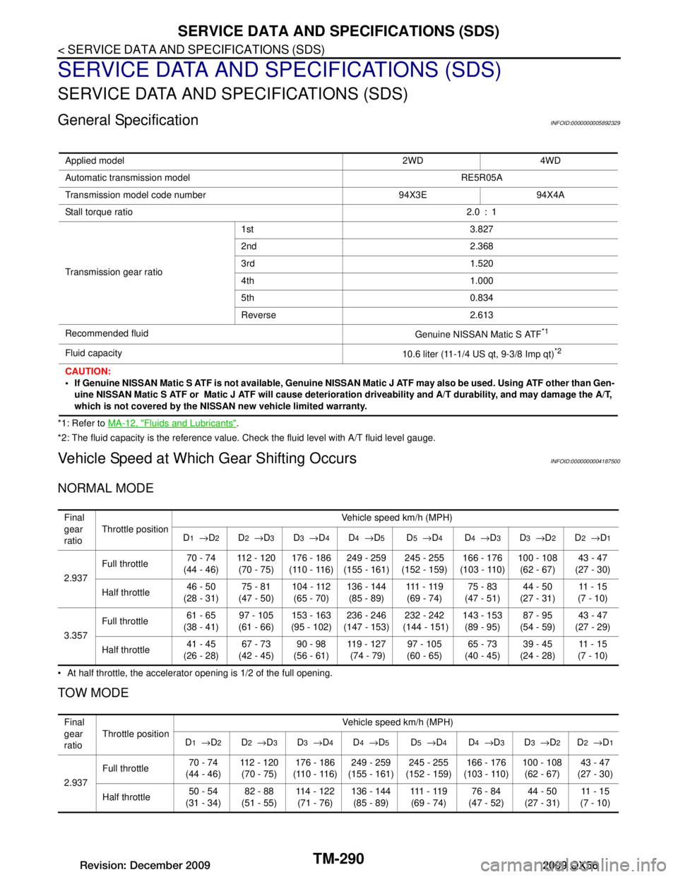
General SpecificationINFOID:0000000005892329
*1: Refer to MA-12, "Fluids and Lubricants".
*2: The fluid capacity is the reference value. Check the fluid level with A/T fluid level gauge.
Vehicle Speed at Which Gear Shifting OccursINFOID:0000000004187500
NORMAL MODE
At half throttle, the accelerator opening is 1/2 of the full opening.
TOW MODE
Applied model 2WD 4WD
Automatic transmission model RE5R05A
Transmission model code number 94X3E 94X4A
Stall torque ratio 2.0 : 1
Transmission gear ratio 1st 3.827
2nd 2.368
3rd 1.520
4th 1.000
5th 0.834
Reverse 2.613
Recommended fluid Genuine NISSAN Matic S ATF
*1
Fluid capacity10.6 liter (11-1/4 US qt, 9-3/8 Imp qt)*2
CAUTION:
If Genuine NISSAN Matic S ATF is not available, Genuine NISSAN Matic J ATF may also be used. Using ATF other than Gen-
uine NISSAN Matic S ATF or Matic J ATF will cause deterioration driveability and A/T durability, and may damage the A/T,
which is not covered by the NISSAN new vehicle limited warranty.
Final
gear
ratio Throttle position
Vehicle speed km/h (MPH)
D
1 → D2D2 → D3D3 → D4D4 → D5D5 → D4D4 → D3D3 → D2D2 → D1
2.937 Full throttle
70 - 74
(44 - 46) 112 - 120
(70 - 75) 176 - 186
(110 - 116) 249 - 259
(155 - 161) 245 - 255
(152 - 159) 166 - 176
(103 - 110) 100 - 108
(62 - 67) 43 - 47
(27 - 30)
Half throttle 46 - 50
(28 - 31) 75 - 81
(47 - 50) 104 - 112
(65 - 70) 136 - 144
(85 - 89) 111 - 11 9
(69 - 74) 75 - 83
(47 - 51) 44 - 50
(27 - 31) 11 - 1 5
(7 - 10)
3.357 Full throttle
61 - 65
(38 - 41) 97 - 105
(61 - 66) 153 - 163
(95 - 102) 236 - 246
(147 - 153) 232 - 242
(144 - 151) 143 - 153
(89 - 95) 87 - 95
(54 - 59) 43 - 47
(27 - 29)
Half throttle 41 - 45
(26 - 28) 67 - 73
(42 - 45) 90 - 98
(56 - 61) 119 - 127
(74 - 79) 97 - 105
(60 - 65) 65 - 73
(40 - 45) 39 - 45
(24 - 28) 11 - 1 5
(7 - 10)
Final
gear
ratio Throttle position Vehicle speed km/h (MPH)
D
1 → D2D2 → D3D3 → D4D4 → D5D5 → D4D4 → D3D3 → D2D2 → D1
2.937 Full throttle
70 - 74
(44 - 46) 112 - 120
(70 - 75) 176 - 186
(110 - 116) 249 - 259
(155 - 161) 245 - 255
(152 - 159) 166 - 176
(103 - 110) 100 - 108
(62 - 67) 43 - 47
(27 - 30)
Half throttle 50 - 54
(31 - 34) 82 - 88
(51 - 55) 114 - 122
(71 - 76) 136 - 144
(85 - 89) 111 - 11 9
(69 - 74) 76 - 84
(47 - 52) 44 - 50
(27 - 31) 11 - 1 5
(7 - 10)
Revision: December 20092009 QX56