oil filter INFINITI QX56 2009 Factory User Guide
[x] Cancel search | Manufacturer: INFINITI, Model Year: 2009, Model line: QX56, Model: INFINITI QX56 2009Pages: 4171, PDF Size: 84.65 MB
Page 1824 of 4171

EM-1
ENGINE
C
DE
F
G H
I
J
K L
M
SECTION EM
A
EM
N
O P
CONTENTS
ENGINE MECHANICAL
PRECAUTION ....... ........................................3
PRECAUTIONS .............................................. .....3
Precaution for Supplemental Restraint System
(SRS) "AIR BAG" and "SEAT BELT PRE-TEN-
SIONER" ............................................................. ......
3
Precaution Necessary for Steering Wheel Rota-
tion After Battery Disconnect ............................... ......
3
Precaution for Drain Engine Coolant .........................4
Precaution for Disconnecting Fuel Piping .................4
Precaution for Removal and Disassembly ................4
Precaution for Inspection, Repair and Replace-
ment .................................................................... ......
4
Precaution for Assembly and Installation ..................4
Parts Requiring Angular Tightening ..........................4
Precaution for Liquid Gasket ............................... ......5
PREPARATION ............................................6
PREPARATION .............................................. .....6
Special Service Tool ........................................... ......6
Commercial Service Tool ..........................................8
FUNCTION DIAGNOSIS ..............................10
NOISE, VIBRATION, AND HARSHNESS
(NVH) TROUBLESHOOTING ........................ ....
10
NVH Troubleshooting - Engine Noise ................. ....10
Use the Chart Below to Help You Find the Cause
of the Symptom .......................................................
11
ON-VEHICLE MAINTENANCE ....................13
DRIVE BELTS ................................................ ....13
Exploded View .................................................... ....13
Checking Drive Belts ...............................................13
Removal and Installation .........................................13
Drive Belt Auto Tensioner and Idler Pulley ......... ....14
AIR CLEANER FILTER ......................................15
Exploded View .................................................... ....15
Removal and Installation (Viscous paper type) .......15
SPARK PLUG ...................................................16
Exploded View ..................................................... ....16
Removal and Installation .........................................16
CAMSHAFT VALVE CLEARANCE ..................18
Valve Clearance ......................................................18
COMPRESSION PRESSURE ...........................23
Checking Compression Pressure ............................23
ON-VEHICLE REPAIR .................................24
ENGINE ROOM COVER ...................................24
Removal and Installation ..................................... ....24
AIR CLEANER AND AIR DUCT .......................25
Exploded View .........................................................25
Removal and Installation .........................................25
INTAKE MANIFOLD .........................................26
Exploded View .........................................................26
Removal and Installation .........................................26
EXHAUST MANIFOLD AND THREE WAY
CATALYST ........................................................
30
Exploded View .........................................................30
Removal and Installation .........................................30
OIL PAN AND OIL STRAINER .........................33
Exploded View .........................................................33
Removal and Installation .........................................33
IGNITION COIL .................................................37
Exploded View .........................................................37
Removal and Installation .........................................37
ROCKER COVER .............................................38
Exploded View .........................................................38
Removal and Installation .........................................38
FUEL INJECTOR AND FUEL TUBE ................40
Exploded View .........................................................40
Removal and Installation .........................................40
Revision: December 20092009 QX56
Page 1856 of 4171

OIL PAN AND OIL STRAINEREM-33
< ON-VEHICLE REPAIR >
C
DE
F
G H
I
J
K L
M A
EM
NP
O
OIL PAN AND OIL STRAINER
Exploded ViewINFOID:0000000005885878
Removal and InstallationINFOID:0000000005885879
REMOVAL
WARNING:
To avoid the danger of being scalded, never drain the engine oil when the engine is hot.
1. Remove the engine. Refer to
EM-78, "
Removal and Installation".
2. Remove the oil pan (lower) using the following steps.
1. Oil pan (upper) 2. O-ring3. O-ring
4. O-ring 5. O-ring (with collar)6. Oil level gauge guide
7. Oil level gauge 8. O-ring9. Connector bolt
10. Oil filter 11. Oil cooler12. Relief valve
13. Oil pressure switch 14. Gasket15. Drain plug
16. Oil pan (lower) 17. Oil strainer
KBIA2465E
Revision: December 20092009 QX56
Page 2223 of 4171

PRECAUTIONSGI-29
< PRECAUTION >
C
DE
F
G H
I
J
K L
M B
GI
N
O P
Dispose of used oil and used oil filters through authorized waste disposal contractors to licensed waste dis-
posal sites, or to the waste oil reclamation trade. If in doubt, contact the local authority for advice on disposal
facilities.
It is illegal to pour used oil on to the ground, down sewers or drains, or into water sources.
The regulations concerning po llution vary between regions.
Air ConditioningINFOID:0000000003771205
Use an approved refrigerant recovery unit any time t he air conditioning system must be discharged. Refer to
HA-20, "
HFC-134a (R-134a) Service Procedure".
Revision: December 20092009 QX56
Page 2656 of 4171

LU-1
ENGINE
C
DE
F
G H
I
J
K L
M
SECTION LU
A
LU
N
O P
CONTENTS
ENGINE LUBRICATION SYSTEM
PRECAUTION ....... ........................................2
PRECAUTIONS .............................................. .....2
Precaution for Supplemental Restraint System
(SRS) "AIR BAG" and "SEAT BELT PRE-TEN-
SIONER" ............................................................. ......
2
Precaution Necessary for Steering Wheel Rota-
tion After Battery Disconnect ............................... ......
2
Precaution for Liquid Gasket .....................................3
PREPARATION ............................................4
PREPARATION .............................................. .....4
Special Service Tool ........................................... ......4
Commercial Service Tool ..........................................4
FUNCTION DIAGNOSIS ...............................6
LUBRICATION SYSTEM ............................... .....6
Lubrication Circuit ............................................... ......6
Schematic .................................................................7
ON-VEHICLE MAINTENANCE .....................8
ENGINE OIL ................................................... .....8
Inspection ............................................................ ......8
Changing Engine Oil ............................................ .....9
OIL FILTER .......................................................11
Removal and Installation .........................................11
ON-VEHICLE REPAIR .................................12
OIL COOLER ....................................................12
Exploded View ..................................................... ....12
Removal and Installation .........................................12
OIL PUMP .........................................................14
Exploded View .........................................................14
Removal and Installation .........................................14
DISASSEMBLY AND ASSEMBLY ..............16
OIL PUMP .........................................................16
Disassembly and Assembly ................................. ....16
SERVICE DATA AND SPECIFICATIONS
(SDS) ............... .......................................... ...
18
SERVICE DATA AND SPECIFICATIONS
(SDS) .................................................................
18
Standard and Limit .............................................. ....18
Revision: December 20092009 QX56
Page 2659 of 4171

LU-4
< PREPARATION >
PREPARATION
PREPARATION
PREPARATION
Special Service ToolINFOID:0000000003771266
The actual shapes of Kent-Moore tools may differ from those of special service tools illustrated here.
Commercial Service ToolINFOID:0000000003771267
Tool number
(Kent-Moore No.)
Tool name Description
ST25051001
(J-25695-1)
Oil pressure gauge Measuring oil pressure
Maximum measuring range:
2,452 kPa (25 kg/cm
2, 356 psi)
ST25052000
(J-25695-2)
Hose Adapting oil pressure gauge to cylinder block
K V 1 0 1111 0 0
(J-37228)
Seal cutter Removing steel oil pan and rear timing chain
case
KV10115801
(J-38956)
Oil filter wrench Removing and installing oil filter
a: 64.3 mm (2.531 in)
WS39930000
(—)
Tube presser Pressing the tube of liquid gasket
S-NT050
S-NT559
NT046
S-NT375
S-NT052
Revision: December 20092009 QX56
Page 2661 of 4171

LU-6
< FUNCTION DIAGNOSIS >
LUBRICATION SYSTEM
FUNCTION DIAGNOSIS
LUBRICATION SYSTEM
Lubrication CircuitINFOID:0000000003771268
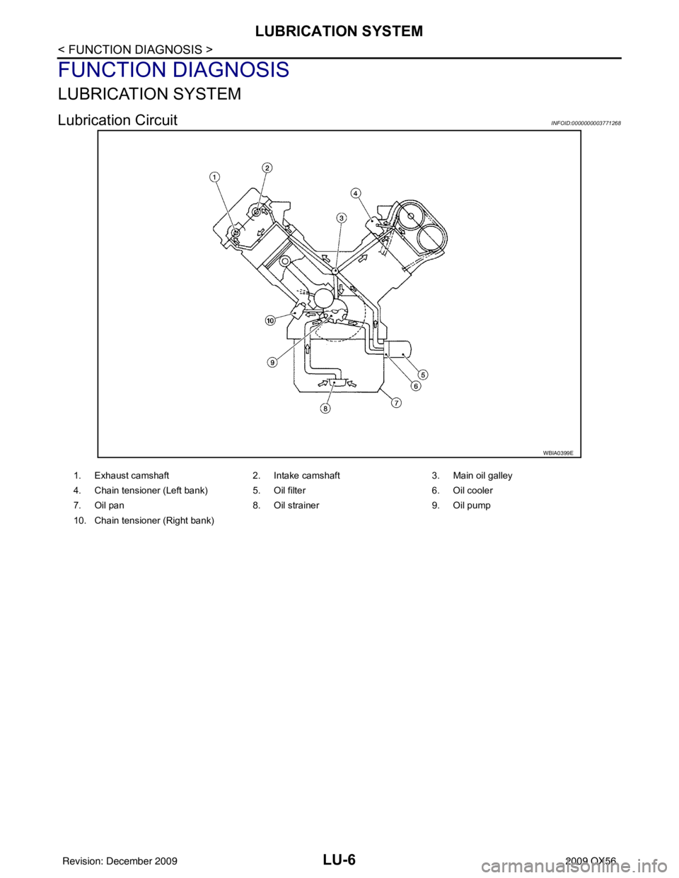
WBIA0399E
1. Exhaust camshaft2. Intake camshaft3. Main oil galley
4. Chain tensioner (Left bank) 5. Oil filter 6. Oil cooler
7. Oil pan 8. Oil strainer 9. Oil pump
10. Chain tensioner (Right bank)
Revision: December 20092009 QX56
Page 2663 of 4171

LU-8
< ON-VEHICLE MAINTENANCE >
ENGINE OIL
ON-VEHICLE MAINTENANCE
ENGINE OIL
InspectionINFOID:0000000003771270
OIL LEVEL
• Before starting the engine make sure the vehicle is parked on a flatand level surface, then check the oil level. If the engine is already
running, turn it off and allow 10 minutes before checking.
• Check that the oil level is within the low (L) and high (H) range as indicated on the dipstick.
• If the engine oil level is out of range, add oil as necessary. Refer to
MA-12, "
Fluids and Lubricants".
OIL APPEARANCE
• Check the engine oil for a white milky appearance or excessive contamination.
• If the engine oil is milky, it is highly probable that it is contaminated with engine coolant. Repair the broken
parts.
OIL LEAKAGE
Check for oil leakage around the following areas:
•Oil pan
• Oil pan drain plug
• Oil pressure switch
• Oil filter
• Oil cooler
• Intake valve timing control cover
• Intake valve timing control solenoid valve
• Front cover
• Mating surface between cylinder block and cylinder head
• Mating surface between cylinder head and rocker cover
• Crankshaft oil seal (front and rear)
OIL PRESSURE CHECK
WARNING:
• Be careful not to burn yoursel f, as engine oil may be hot.
• Put the A/T shift selector in the Park “P” position.
1. Check the engine oil level. Refer to LU-8, "
Inspection".
2. Remove engine front undercover using power tool.
3. Disconnect the oil pressure switch harness connector.
4. Remove the oil pressure switch (A).
SMA954C
WBIA0791E
Revision: December 20092009 QX56
Page 2665 of 4171

LU-10
< ON-VEHICLE MAINTENANCE >
ENGINE OIL
Unit: (US qt, Imp qt)
CAUTION:
• The refill capacity depends on the engine oil temperature and drain time. Use these specifica-
tions for reference only.
• Always use the oil level gauge to determine when the proper amount of engine oil is in the engine.
8. Warm up engine and check area around drain plug and oil filter for oil leakage.
9. Stop engine and wait for 10 minutes.
10. Check engine oil level. Refer to LU-8, "
Inspection".
Drain and refill With oil filter change
6.5 (6 7/8, 5-3/4)
Without oil filter change 6.2 (6-1/2, 5-1/2)
Dry engine (engine overhaul) 7.6 (8, 6-3/4)
Revision: December 20092009 QX56
Page 2666 of 4171

OIL FILTERLU-11
< ON-VEHICLE MAINTENANCE >
C
DE
F
G H
I
J
K L
M A
LU
NP
O
OIL FILTER
Removal and InstallationINFOID:0000000003771272
REMOVAL
1. Drain the engine oil. Refer to
LU-9, "Changing Engine Oil".
2. Remove the oil filter using Tool.
WARNING:
Be careful not to get burned when the engine and engine oil
are hot.
CAUTION:
• The oil filter is provided with a relief valve.
• Use Genuine NISSAN oil filter or equivalent.
• When removing, prepare a s hop cloth to absorb any
engine oil leakage or spillage.
• Do not allow engine oil to adhere to the drive belts.
• Completely wipe off any engine oil that adheres to the engine and the vehicle.
INSTALLATION
1. Remove foreign materials adhering to the oil filter installation surface.
2. Apply engine oil to the oil seal circumference of the new oil filter.
3. Screw the oil filter manually until it touches the installation sur-
face, then tighten it by 2/3 turn. Or tighten to specification.
4. Refill the engine with new engine oil. Refer to LU-9, "
Changing
Engine Oil".
5. Inspect the engine for oil leakage. Follow the "INSPECTION AFTER INSTALLATION" procedure.
INSPECTION AFTER INSTALLATION
1. Check the engine oil level. Refer to LU-8, "Inspection".
2. Start the engine and check for engine oil leakage.
3. Stop the engine and wait for 10 minutes.
4. Check the engine oil level and add engine oil as required. Tool number : KV10115801 (J-38956)
WBIA0388E
SMA010
Oil filter : 17.7 N·m (1.8 kg-m, 13 ft-lb)
SMA229B
Revision: December 20092009 QX56
Page 2667 of 4171

LU-12
< ON-VEHICLE REPAIR >
OIL COOLER
ON-VEHICLE REPAIR
OIL COOLER
Exploded ViewINFOID:0000000004115483
Removal and InstallationINFOID:0000000003771273
WARNING:
Be careful not to burn yourself, as the engine oil and engine coolant are hot.
REMOVAL
1. Drain engine coolant from the radiator. Refer to CO-11, "Changing Engine Coolant".
2. Disconnect water hoses from the oil cooler. CAUTION:
Do not spill engine coolant on the drive belt.
3. Remove oil filter. Refer to LU-11, "
Removal and Installation".
CAUTION:
Do not spill engine oil on the drive belt.
4. Remove connector bolt, and remove oil cooler and O-ring.
INSPECTION AFTER REMOVAL
Oil Cooler
Check oil cooler for cracks. Check oil cooler for clogging by blowing compressed air through engine coolant
inlet. If necessary, replace oil cooler assembly.
1. Oil pan 2. Water hose3. Water pipe
4. Water hose 5. Connector bolt 6. Oil filter
7. Oil cooler 8. O-ring 9. Relief valve
10. Water hose 11. Connector pipe 12. Gasket
A. To thermostat housing B. Refer to LU-11
C. To cylinder block
WBIA0790E
Revision: December 20092009 QX56