Abs INFINITI QX56 2009 Factory Service Manual
[x] Cancel search | Manufacturer: INFINITI, Model Year: 2009, Model line: QX56, Model: INFINITI QX56 2009Pages: 4171, PDF Size: 84.65 MB
Page 2240 of 4171

GI-46
< BASIC INSPECTION >
CONSULT-III CHECKING SYSTEM
CONSULT-III CHECKING SYSTEM
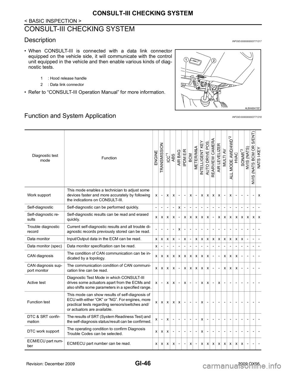
DescriptionINFOID:0000000003771217
• When CONSULT-III is connected with a data link connectorequipped on the vehicle side, it will communicate with the control
unit equipped in the vehicle and then enable various kinds of diag-
nostic tests.
• Refer to “CONSULT-III Operation Manual” for more information.
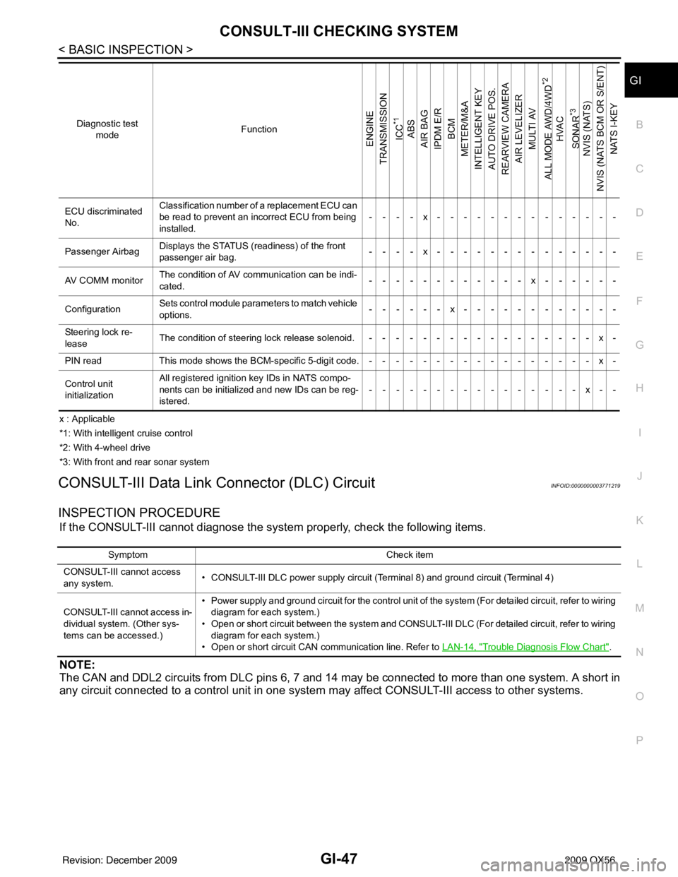
Function and System ApplicationINFOID:0000000003771218
1 : Hood release handle
2 : Data link connector
ALBIA0047ZZ
Diagnostic test mode Function
ENGINE
TRANSMISSION
ICC
*1
ABS
AIR BAG
IPDM E/R BCM
METER/M&A
INTELLIGENT KEY
AUTO DRIVE POS.
REARVIEW CAMERA AIR LEVELIZER MULTI AV
ALL MODE AWD/4WD
*2
HVAC
SONAR
*3
NVIS (NATS)
NVIS (NATS BCM OR S/ENT) NATS I-KEY
Work support This mode enables a technician to adjust some
devices faster and more accurately by following
the indications on CONSULT-III. x-xx--x-xxxx-x----x
Self-diagnostic Self-diagnostic can be performed quickly. ----x--------------
Self-diagnostic re-
sults Self-diagnostic results can be read and erased
quickly.
xxx x- xxxxx- xxx xxxxx
Trouble diagnostic
record Current self-diagnostic results and all trouble di-
agnostic records previously stored can be read.
--- - x--- - ----------
Data monitor Input/Output data in the ECM can be read. xxx x- x- xxxxxxx xx- - -
Data monitor (spec) Data monitor specification can be read. x------------------
CAN diagnosis The condition of CAN communication can be in-
dicated by a topology.
xxx xxxxxxx- - xx x- - - -
CAN diagnosis sup-
port monitor The communication condition of CAN communi-
cation line can be read.
xxx x- xxxxx- - xx x- - - -
Active test Diagnostic Test Mode
in which CONSULT-III
drives some actuators apart from the ECMs and
also shifts some parameters in a specified range. x-xx-x--xx-x-------
Function test This mode can show results of self-diagnosis of
ECU with either “OK” or “NG”. For engines, more
practical tests regarding sensors/switches and/
or actuators are available. xxxxx---x----------
DTC & SRT confir-
mation The results of SRT (System Readiness Test) and
the self-diagnosis status/result can be confirmed.
x-x-----x----------
DTC work support The operating condition to confirm Diagnosis
Trouble Codes can be selected. xxx-----x----------
ECM/ECU part num-
ber ECM/ECU part number can be read.
xxx x- - x- xxxxxx xx- - -
Revision: December 20092009 QX56
Page 2241 of 4171

CONSULT-III CHECKING SYSTEMGI-47
< BASIC INSPECTION >
C
DE
F
G H
I
J
K L
M B
GI
N
O P
x : Applicable
*1: With intelligent cruise control
*2: With 4-wheel drive
*3: With front and rear sonar system
CONSULT-III Data Link Connector (DLC) CircuitINFOID:0000000003771219
INSPECTION PROCEDURE
If the CONSULT-III cannot diagnose the sys tem properly, check the following items.
NOTE:
The CAN and DDL2 circuits from DLC pins 6, 7 and 14 may be connected to more than one system. A short in
any circuit connected to a control unit in one system may affect CONSULT-III access to other systems.
ECU discriminated
No.Classification number of a replacement ECU can
be read to prevent an incorrect ECU from being
installed.
----x--------------
Passenger Airbag Displays the STATUS (readiness) of the front
passenger air bag.
----x--------------
AV COMM monitor The condition of AV communication can be indi-
cated. ------------x------
Configuration Sets control module para
meters to match vehicle
options. ------x------------
Steering lock re-
lease The condition of steering lock release solenoid. -----------------x-
PIN read This mode shows the BCM-specific 5-digit code.-----------------x-
Control unit
initialization All registered ignition key IDs in NATS compo-
nents can be initialized and new IDs can be reg-
istered.
----------------x--
Diagnostic test
mode Function
ENGINE
TRANSMISSION
ICC
*1
ABS
AIR BAG
IPDM E/R BCM
METER/M&A
INTELLIGENT KEY
AUTO DRIVE POS.
REARVIEW CAMERA AIR LEVELIZER
MULTI AV
ALL MODE AWD/4WD
*2
HVAC
SONAR
*3
NVIS (NATS)
NVIS (NATS BCM OR S/ENT) NATS I-KEY
Symptom Check item
CONSULT-III cannot access
any system. • CONSULT-III DLC power supply circuit (Terminal 8) and ground circuit (Terminal 4)
CONSULT-III cannot access in-
dividual system. (Other sys-
tems can be accessed.) • Power supply and ground circuit for the control unit of the system (For detailed circuit, refer to wiring
diagram for each system.)
• Open or short circuit between the system and CONSULT-III DLC (For detailed circuit, refer to wiring diagram for each system.)
• Open or short circuit CAN communication line. Refer to LAN-14, "
Trouble Diagnosis Flow Chart".
Revision: December 20092009 QX56
Page 2268 of 4171

HA-4
< PRECAUTION >
PRECAUTIONS
5. When the repair work is completed, return the ignition switch to the ″LOCK ″ position before connecting
the battery cables. (At this time, the steering lock mechanism will engage.)
6. Perform a self-diagnosis check of a ll control units using CONSULT-III.
Precaution for Working with HFC-134a (R-134a)INFOID:0000000003775286
WARNING:
CFC-12 (R-12) refrigerant and HFC-134a (R-134a) refr igerant are not compatible. If the refrigerants
are mixed compressor failure is likely to occur. Refer to HA-4, "Contaminated Refrigerant"
. To deter-
mine the purity of HFC-134a (R-134a) in the vehicle and recovery tank, use recovery/recycling equip-
ment and refrigerant identifier.
Use only specified oil for the HFC-134a (R-134a) A/C system and HFC-134a (R-134a) components. If
oil other than that specified is used , compressor failure is likely to occur.
The specified HFC-134a (R-134a) oi l rapidly absorbs moisture from the atmosphere. The following
handling precautions must be observed:
- When removing refrigerant components from a vehicle, immediately cap (seal) the component to
minimize the entry of moisture from the atmosphere.
- When installing refrigerant co mponents to a vehicle, do not remove the caps (unseal) until just
before connecting the components . Connect all refrigerant loop components as quickly as possible
to minimize the entry of moisture into system.
- Only use the specified oil from a sealed container. Immediately reseal containers of oil. Without
proper sealing, oil will become moisture saturat ed and should not be used.
- Avoid breathing A/C refrigerant and oil vapor or mist. Exposure may irritate eyes, nose and throat.
Remove HFC-134a (R-134a) from the A/C system usin g certified service equipment meeting require-
ments of SAE J2210 [HFC-134a (R-134a) recycling equipment], or J2209 [HFC-134a (R-134a) recovery
equipment]. If accidental system discharge occurs , ventilate work area before resuming service.
Additional health and safety in formation may be obtained from refrigerant and oil manufacturers.
- Do not allow A/C oil to come in contact with styrofoam parts. Damage may result.
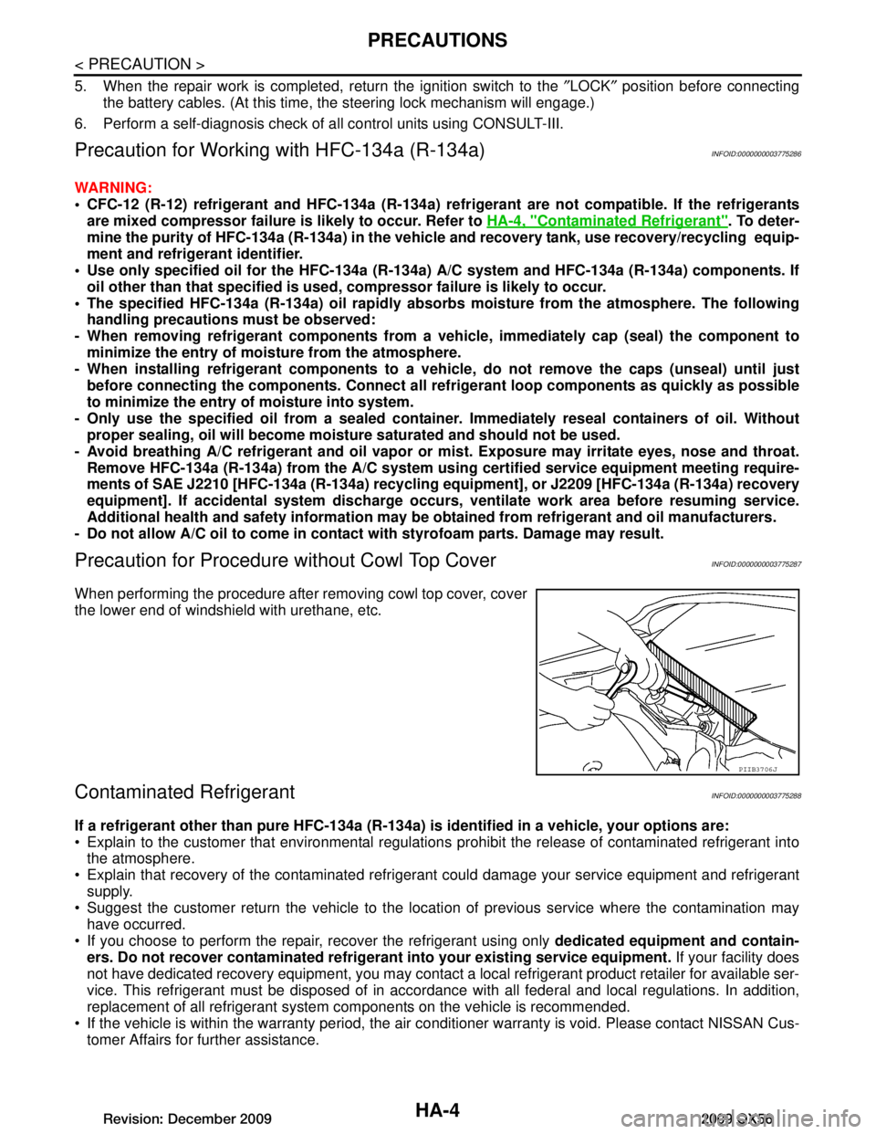
Precaution for Procedure without Cowl Top CoverINFOID:0000000003775287
When performing the procedure after removing cowl top cover, cover
the lower end of windshield with urethane, etc.
Contaminated RefrigerantINFOID:0000000003775288
If a refrigerant other than pure HFC-134a (R-134a) is identified in a vehicle, your options are:
Explain to the customer that environmental regulations prohibit the release of contaminated refrigerant into
the atmosphere.
Explain that recovery of the contaminated refri gerant could damage your service equipment and refrigerant
supply.
Suggest the customer return the vehicle to the locati on of previous service where the contamination may
have occurred.
If you choose to perform the repair, recover the refrigerant using only dedicated equipment and contain-
ers. Do not recover contamin ated refrigerant into your existing service equipment. If your facility does
not have dedicated recovery equipment, you may contact a local refrigerant product retailer for available ser-
vice. This refrigerant must be disposed of in acco rdance with all federal and local regulations. In addition,
replacement of all refrigerant system components on the vehicle is recommended.
If the vehicle is within the warranty period, the air conditioner warranty is void. Please contact NISSAN Cus-
tomer Affairs for further assistance.
PIIB3706J
Revision: December 20092009 QX56
Page 2436 of 4171
![INFINITI QX56 2009 Factory Service Manual PRECAUTIONSHAC-123
< PRECAUTION > [AUTOMATIC AIR CONDITIONER]
C
D
E
F
G H
J
K L
M A
B
HAC
N
O P
PRECAUTION
PRECAUTIONS
Precaution for Supplemental Restraint System (SRS) "AIR BAG" and "SEAT BELT
PRE INFINITI QX56 2009 Factory Service Manual PRECAUTIONSHAC-123
< PRECAUTION > [AUTOMATIC AIR CONDITIONER]
C
D
E
F
G H
J
K L
M A
B
HAC
N
O P
PRECAUTION
PRECAUTIONS
Precaution for Supplemental Restraint System (SRS) "AIR BAG" and "SEAT BELT
PRE](/img/42/57031/w960_57031-2435.png)
PRECAUTIONSHAC-123
< PRECAUTION > [AUTOMATIC AIR CONDITIONER]
C
D
E
F
G H
J
K L
M A
B
HAC
N
O P
PRECAUTION
PRECAUTIONS
Precaution for Supplemental Restraint System (SRS) "AIR BAG" and "SEAT BELT
PRE-TENSIONER"
INFOID:0000000005867494
The Supplemental Restraint System such as “AIR BAG” and “SEAT BELT PRE-TENSIONER”, used along
with a front seat belt, helps to reduce the risk or severi ty of injury to the driver and front passenger for certain
types of collision. This system includes seat belt switch inputs and dual stage front air bag modules. The SRS
system uses the seat belt switches to determine the front air bag deployment, and may only deploy one front
air bag, depending on the severity of a collision and w hether the front occupants are belted or unbelted.
Information necessary to service the system safely is included in the SR and SB section of this Service Man-
ual.
WARNING:
• To avoid rendering the SRS inoper ative, which could increase the risk of personal injury or death in
the event of a collision which would result in air bag inflation, all maintenance must be performed by
an authorized NISSAN/INFINITI dealer.
• Improper maintenance, including in correct removal and installation of the SRS, can lead to personal
injury caused by unintentional act ivation of the system. For removal of Spiral Cable and Air Bag
Module, see the SR section.
• Do not use electrical test equipm ent on any circuit related to the SRS unless instructed to in this
Service Manual. SRS wiring harnesses can be identi fied by yellow and/or orange harnesses or har-
ness connectors.
PRECAUTIONS WHEN USING POWER TOOLS (AIR OR ELECTRIC) AND HAMMERS
WARNING:
• When working near the Airbag Diagnosis Sensor Un it or other Airbag System sensors with the Igni-
tion ON or engine running, DO NOT use air or el ectric power tools or strike near the sensor(s) with a
hammer. Heavy vibration could activate the sensor( s) and deploy the air bag(s), possibly causing
serious injury.
• When using air or electric power tools or hammers, always switch the Ignition OFF, disconnect the battery, and wait at least 3 minutes before performing any service.
Working with HFC-134a (R-134a)INFOID:0000000003775400
WARNING:
• CFC-12 (R-12) refrigerant and HFC-134a (R-134a) refr igerant are not compatible. If the refrigerants
are mixed compressor failure is likely to occur. Refer to HA-4, "
Contaminated Refrigerant". To deter-
mine the purity of HFC-134a (R-134a) in the vehic le and recovery tank, use Refrigerant Recovery/
Recycling Recharging equipment and Refrigerant Identifier.
• Use only specified oil for the HFC-134a (R-134a) A/C system and HFC-134a (R-134a) components. If oil other than that specified is used, compressor fa ilure is likely to occur.
• The specified HFC-134a (R-134a) oil rapidly absorb s moisture from the atmosphere. The following
handling precautions must be observed:
- When removing refrigerant components from a vehicle, immediately cap (seal) the component to
minimize the entry of mois ture from the atmosphere.
- When installing refrigerant components to a vehicle, do not remove the caps (unseal) until just
before connecting the co mponents. Connect all refrigerant lo op components as quickly as possible
to minimize the entry of moisture into system.
- Only use the specified oil from a sealed container. Immediately r eseal containers of oil. Without
proper sealing, oil will become moisture saturat ed and should not be used.
- Avoid breathing A/C refrigerant and oil vapor or mist. Exposure may irritate eyes, nose and throat.
Remove HFC-134a (R-134a) from the A/C system usi ng certified service equipment meeting require-
ments of SAE J2210 [HFC-134a (R-134a) recycling equipment], or J2209 [HFC-134a (R-134a) recy-
cling equipment], If accidental system discharge occurs, ventilate work area before resuming
service. Additional health and safety information may be obtained from refrigerant and oil manufac-
turers.
- Do not allow A/C oil to come in contact with styrofoam parts. Damage may result.
CONTAMINATED REFRIGERANT
Revision: December 20092009 QX56
Page 2518 of 4171

INL-74
< ON-VEHICLE REPAIR >
INTERIOR ROOM LAMP
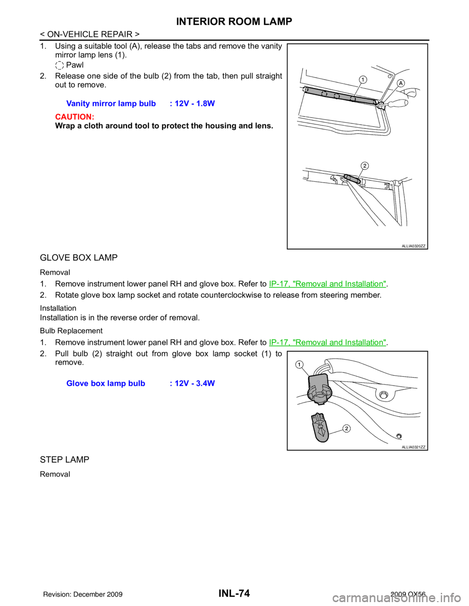
1. Using a suitable tool (A), release the tabs and remove the vanitymirror lamp lens (1).
Pawl
2. Release one side of the bulb (2) from the tab, then pull straight out to remove.
CAUTION:
Wrap a cloth around tool to protect the housing and lens.
GLOVE BOX LAMP
Removal
1. Remove instrument lower panel RH and glove box. Refer to IP-17, "Removal and Installation".
2. Rotate glove box lamp socket and rotate counterclockwise to release from steering member.
Installation
Installation is in the reverse order of removal.
Bulb Replacement
1. Remove instrument lower panel RH and glove box. Refer to IP-17, "Removal and Installation".
2. Pull bulb (2) straight out from glove box lamp socket (1) to remove.
STEP LAMP
Removal
Vanity mirror lamp bulb : 12V - 1.8W
ALLIA0320ZZ
Glove box lamp bulb : 12V - 3.4W
ALLIA0321ZZ
Revision: December 20092009 QX56
Page 2571 of 4171

LAN-2
MAIN LINE BETWEEN TCM AND LASER
CIRCUIT .............................................................
63
Diagnosis Procedure ........................................... ...63
MAIN LINE BETWEEN LASER AND ICC CIR-
CUIT ...................................................................
64
Diagnosis Procedure ........................................... ...64
MAIN LINE BETWEEN ICC AND ADP CIR-
CUIT ...................................................................
65
Diagnosis Procedure ........................................... ...65
MAIN LINE BETWEEN ADP AND AV CIR-
CUIT ...................................................................
66
Diagnosis Procedure ........................................... ...66
MAIN LINE BETWEEN AV AND DLC CIR-
CUIT ...................................................................
67
Diagnosis Procedure ........................................... ...67
MAIN LINE BETWEEN DLC AND M&A CIR-
CUIT ...................................................................
68
Diagnosis Procedure ........................................... ...68
MAIN LINE BETWEEN M&A AND ABS CIR-
CUIT ...................................................................
69
Diagnosis Procedure ........................................... ...69
ECM BRANCH LINE CIRCUIT ..........................70
Diagnosis Procedure ........................................... ...70
TCM BRANCH LINE CIRCUIT ..........................71
Diagnosis Procedure ........................................... ...71
LASER BRANCH LINE CIRCUIT ......................72
Diagnosis Procedure ........................................... ...72
ICC BRANCH LINE CIRCUIT ............................73
Diagnosis Procedure ............................................ ...73
ADP BRANCH LINE CIRCUIT ..........................74
Diagnosis Procedure ............................................ ...74
AV BRANCH LINE CIRCUIT .............................75
Diagnosis Procedure ............................................ ...75
BCM BRANCH LINE CIRCUIT ..........................76
Diagnosis Procedure ............................................ ...76
DLC BRANCH LINE CIRCUIT ..........................77
Diagnosis Procedure ............................................ ...77
HVAC BRANCH LINE CIRCUIT ........................78
Diagnosis Procedure ............................................ ...78
I-KEY BRANCH LINE CIRCUIT ........................79
Diagnosis Procedure ............................................ ...79
M&A BRANCH LINE CIRCUIT ..........................80
Diagnosis Procedure ............................................ ...80
STRG BRANCH LINE CIRCUIT ........................81
Diagnosis Procedure ............................................ ...81
4WD BRANCH LINE CIRCUIT ..........................82
Diagnosis Procedure ............................................ ...82
ABS BRANCH LINE CIRCUIT ..........................83
Diagnosis Procedure ............................................ ...83
IPDM-E BRANCH LINE CIRCUIT .....................84
Diagnosis Procedure ............................................ ...84
CAN COMMUNICATION CIRCUIT ...................85
Diagnosis Procedure ............................................ ...85
Revision: December 20092009 QX56
Page 2577 of 4171
![INFINITI QX56 2009 Factory Service Manual LAN-8
< FUNCTION DIAGNOSIS >[CAN FUNDAMENTAL]
TROUBLE DIAGNOSIS
Example: Data link connector branch line open circuit
NOTE:
• When data link connector branch line is open, transmission and reception INFINITI QX56 2009 Factory Service Manual LAN-8
< FUNCTION DIAGNOSIS >[CAN FUNDAMENTAL]
TROUBLE DIAGNOSIS
Example: Data link connector branch line open circuit
NOTE:
• When data link connector branch line is open, transmission and reception](/img/42/57031/w960_57031-2576.png)
LAN-8
< FUNCTION DIAGNOSIS >[CAN FUNDAMENTAL]
TROUBLE DIAGNOSIS
Example: Data link connector branch line open circuit
NOTE:
• When data link connector branch line is open, transmission and reception of CAN communication signals
are not affected. Therefore, no symptoms occur. However, be sure to repair malfunctioning circuit.
• When data link connector branch line is open, “ECU list” displayed on the CONSULT-III “CAN DIAG SUP- PORT MNTR” may be the same as when the CAN communication line has short-circuit. However, symp-
toms differ depending on the case. See below chart for the differences.
EPS control unit Normal operation.
Combination meter • Shift position indicator and OD OFF indicator turn OFF.
• Warning lamps turn ON.
ABS actuator and electric unit (control unit) Normal operation.
TCM No impact on operation.
IPDM E/R Normal operation.
Unit name
Symptom
SKIB8739E
Unit nameSymptom
ECM
Normal operation.
BCM
EPS control unit
Combination meter
ABS actuator and electric unit (control unit)
TCM
IPDM E/R
“ECU list” on the “CAN DIAG SUPPORT MNTR”(CONSULT-III) Difference of symptom
Data link connector branch line open circuit All Diag on CAN units are not
indicated.Normal operation.
CAN-H, CAN-L harness short-circuit Most of the units which are connected to the CAN
communication system enter fail-safe mode or are
deactivated.
Revision: December 20092009 QX56
Page 2578 of 4171
![INFINITI QX56 2009 Factory Service Manual LAN
TROUBLE DIAGNOSISLAN-9
< FUNCTION DIAGNOSIS > [CAN FUNDAMENTAL]
C
D
E
F
G H
I
J
K L
B A
O P
N
Example: Main Line Between Data Link Connector and ABS Actuator and Electr
ic Unit (Control Unit) Open INFINITI QX56 2009 Factory Service Manual LAN
TROUBLE DIAGNOSISLAN-9
< FUNCTION DIAGNOSIS > [CAN FUNDAMENTAL]
C
D
E
F
G H
I
J
K L
B A
O P
N
Example: Main Line Between Data Link Connector and ABS Actuator and Electr
ic Unit (Control Unit) Open](/img/42/57031/w960_57031-2577.png)
LAN
TROUBLE DIAGNOSISLAN-9
< FUNCTION DIAGNOSIS > [CAN FUNDAMENTAL]
C
D
E
F
G H
I
J
K L
B A
O P
N
Example: Main Line Between Data Link Connector and ABS Actuator and Electr
ic Unit (Control Unit) Open Circuit
Example: CAN-H, CAN-L Harness Short Circuit
SKIB8740E
Unit name Symptom
ECM Engine torque limiting is affected, and shift harshness increases.
BCM • Reverse warning chime does not sound.
• The front wiper moves under continuous operation mode even though the front wip-
er switch being in the intermittent position.
EPS control unit The steering effort increases.
Combination meter • The shift position indicator and OD OFF indicator turn OFF.
• The speedometer is inoperative.
• The odo/trip meter stops.
ABS actuator and electric unit (control unit) Normal operation.
TCM No impact on operation.
IPDM E/R When the ignition switch is ON,
• The headlamps (Lo) turn ON.
• The cooling fan continues to rotate.
SKIB8741E
Revision: December 20092009 QX56
Page 2579 of 4171
![INFINITI QX56 2009 Factory Service Manual LAN-10
< FUNCTION DIAGNOSIS >[CAN FUNDAMENTAL]
TROUBLE DIAGNOSIS
Self-Diagnosis
INFOID:0000000003776437
CAN Diagnostic Support MonitorINFOID:0000000003776438
CONSULT-III and CAN diagnostic support mon INFINITI QX56 2009 Factory Service Manual LAN-10
< FUNCTION DIAGNOSIS >[CAN FUNDAMENTAL]
TROUBLE DIAGNOSIS
Self-Diagnosis
INFOID:0000000003776437
CAN Diagnostic Support MonitorINFOID:0000000003776438
CONSULT-III and CAN diagnostic support mon](/img/42/57031/w960_57031-2578.png)
LAN-10
< FUNCTION DIAGNOSIS >[CAN FUNDAMENTAL]
TROUBLE DIAGNOSIS
Self-Diagnosis
INFOID:0000000003776437
CAN Diagnostic Support MonitorINFOID:0000000003776438
CONSULT-III and CAN diagnostic support monitor (on-boar d diagnosis function) are used for detecting root
cause.
MONITOR ITEM (CONSULT-III)
Unit name Symptom
ECM • Engine torque limiting is affected, and shift harshness increases.
• Engine speed drops.
BCM • Reverse warning chime does not sound.
• The front wiper moves under continuous operation mode even though the front
wiper switch being in the intermittent position.
• The room lamp does not turn ON.
• The engine does not start (if an error or malfunction occurs while turning the igni- tion switch OFF.)
• The steering lock does not release (if an error or malfunction occurs while turning the ignition switch OFF.)
EPS control unit The steering effort increases.
Combination meter • The tachometer and the speedometer do not move.
• Warning lamps turn ON.
• Indicator lamps do not turn ON.
ABS actuator and electric unit (control unit) Normal operation.
TCM No impact on operation.
IPDM E/R When the ignition switch is ON,
• The headlamps (Lo) turn ON.
• The cooling fan continues to rotate.
DTC
Self-diagnosis item
(CONSULT-III indication) DTC detection condition
Inspection/Action
U1000 CAN COMM CIRCUIT When ECM is not transmitting or receiving CAN
communication signal of OBD (emission-related
diagnosis) for 2 seconds or more.
Refer to LAN-13
.
When a control unit (except for ECM) is not
transmitting or receiving CAN communication
signal for 2 seconds or more.
U1001 CAN COMM CIRCUIT When ECM is not transmitting or receiving CAN
communication signal other than OBD (emis-
sion-related diagnosis) for 2 seconds or more.
U1002 SYSTEM COMM When a control unit is not transmitting or receiv-
ing CAN communication signal for 2 seconds or
less. Start the inspection. Re-
fer to the applicable sec-
tion of the indicated
control unit.
U1010 CONTROL UNIT(CAN) When an error is detected during the initial diag-
nosis for CAN controller of each control unit. Replace the control unit
indicating “U1010”.
Revision: December 20092009 QX56
Page 2594 of 4171
![INFINITI QX56 2009 Factory Service Manual LAN
DIAGNOSIS AND REPAIR WORKFLOWLAN-25
< BASIC INSPECTION > [CAN FUNDAMENTAL]
C
D
E
F
G H
I
J
K L
B A
O P
N
h. Reception item of “ABS”: “UNKWN” is not indicated. This indicates normal communi INFINITI QX56 2009 Factory Service Manual LAN
DIAGNOSIS AND REPAIR WORKFLOWLAN-25
< BASIC INSPECTION > [CAN FUNDAMENTAL]
C
D
E
F
G H
I
J
K L
B A
O P
N
h. Reception item of “ABS”: “UNKWN” is not indicated. This indicates normal communi](/img/42/57031/w960_57031-2593.png)
LAN
DIAGNOSIS AND REPAIR WORKFLOWLAN-25
< BASIC INSPECTION > [CAN FUNDAMENTAL]
C
D
E
F
G H
I
J
K L
B A
O P
N
h. Reception item of “ABS”: “UNKWN” is not indicated. This indicates normal communication between ABS
and its receiving units. Do not draw any line.
i. Reception item of “IPDM-E”: “UNKWN” is not indicated. This indicates normal communication between IPDM-E and its receiving units. Do not draw any line.
3. Based on information received from “CAN DIAG SUPPORT MNTR”, place a check mark on the known good CAN communication line between ECM and IPDM-E.
a. Through the previous procedure, the circuit betw een ADP splice and TCM has the most amount of lines
(shade 3-a in the figure below).
b. Place a check mark on the known good lines to establish the error circuit.
PKID1217E
Revision: December 20092009 QX56