wiring diagram INFINITI QX56 2009 Factory Service Manual
[x] Cancel search | Manufacturer: INFINITI, Model Year: 2009, Model line: QX56, Model: INFINITI QX56 2009Pages: 4171, PDF Size: 84.65 MB
Page 3754 of 4171

TM-106
< ECU DIAGNOSIS >
TCM
Wiring Diagram —A/T CONTROL SYSTEM —
INFOID:0000000003771986
AADWA0088GB
Revision: December 20092009 QX56
Page 3957 of 4171

HEATER & COOLING UNIT ASSEMBLYVTL-17
< ON-VEHICLE REPAIR >
C
DE
F
G H
J
K L
M A
B
VTL
N
O P
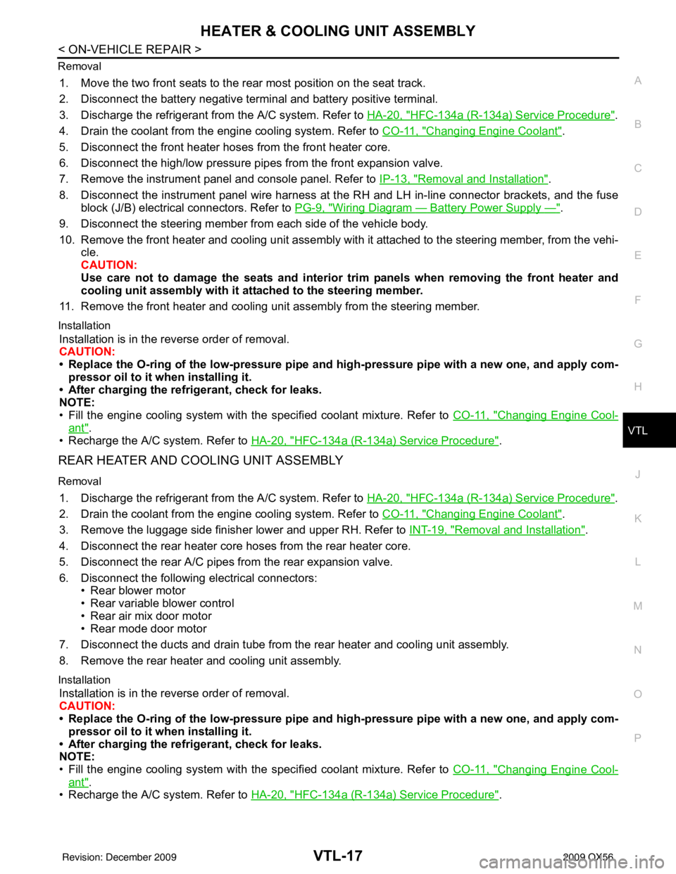
Removal
1. Move the two front seats to the rear most position on the seat track.
2. Disconnect the battery negative terminal and battery positive terminal.
3. Discharge the refrigerant from the A/C system. Refer to
HA-20, "
HFC-134a (R-134a) Service Procedure".
4. Drain the coolant from the engine cooling system. Refer to CO-11, "
Changing Engine Coolant".
5. Disconnect the front heater hoses from the front heater core.
6. Disconnect the high/low pressure pipes from the front expansion valve.
7. Remove the instrument panel and console panel. Refer to IP-13, "
Removal and Installation".
8. Disconnect the instrument panel wire harness at t he RH and LH in-line connector brackets, and the fuse
block (J/B) electrical connectors. Refer to PG-9, "
Wiring Diagram — Battery Power Supply —".
9. Disconnect the steering member from each side of the vehicle body.
10. Remove the front heater and cooling unit assembly with it attached to the steering member, from the vehi- cle.
CAUTION:
Use care not to damage the seats and interior trim panels when removing the front heater and
cooling unit assembly with it at tached to the steering member.
11. Remove the front heater and cooling uni t assembly from the steering member.
Installation
Installation is in the reverse order of removal.
CAUTION:
• Replace the O-ring of the low-pressure pipe and high-pressure pipe with a new one, and apply com-
pressor oil to it when installing it.
• After charging the refrigerant, check for leaks.
NOTE:
• Fill the engine cooling system with the specified coolant mixture. Refer to CO-11, "
Changing Engine Cool-
ant".
• Recharge the A/C system. Refer to HA-20, "
HFC-134a (R-134a) Service Procedure".
REAR HEATER AND COOLING UNIT ASSEMBLY
Removal
1. Discharge the refrigerant from the A/C system. Refer to HA-20, "HFC-134a (R-134a) Service Procedure".
2. Drain the coolant from the engine cooling system. Refer to CO-11, "
Changing Engine Coolant".
3. Remove the luggage side finisher lower and upper RH. Refer to INT-19, "
Removal and Installation".
4. Disconnect the rear heater core hoses from the rear heater core.
5. Disconnect the rear A/C pipes from the rear expansion valve.
6. Disconnect the following electrical connectors: • Rear blower motor
• Rear variable blower control
• Rear air mix door motor
• Rear mode door motor
7. Disconnect the ducts and drain tube from the rear heater and cooling unit assembly.
8. Remove the rear heater and cooling unit assembly.
Installation
Installation is in the reverse order of removal.
CAUTION:
• Replace the O-ring of the low-pressure pipe and high-pressure pipe with a new one, and apply com- pressor oil to it when installing it.
• After charging the refrigerant, check for leaks.
NOTE:
• Fill the engine cooling system with the specified coolant mixture. Refer to CO-11, "
Changing Engine Cool-
ant".
• Recharge the A/C system. Refer to HA-20, "
HFC-134a (R-134a) Service Procedure".
Revision: December 20092009 QX56
Page 3979 of 4171

WCS-2
WARNING CHIME SYSTEM .............................23
Wiring Diagram .................................................... ...23
ECU DIAGNOSIS ..................................... ...28
COMBINATION METER ................................. ...28
Reference Value .................................................. ...28
Wiring Diagram .......................................................30
Fail Safe .................................................................46
DTC Index ..............................................................47
BCM (BODY CONTROL MODULE) ..................49
Reference Value .................................................. ...49
Terminal Layout ......................................................51
Physical Values ......................................................51
Wiring Diagram .......................................................57
SYMPTOM DIAGNOSIS .............................62
THE LIGHT REMINDER WARNING DOES
NOT SOUND ................................................... ...
62
Description ........................................................... ...62
Diagnosis Procedure ...............................................62
THE SEAT BELT WARNING CONTINUES
SOUNDING, OR DOES NOT SOUND ...............
63
Description ........................................................... ...63
Diagnosis Procedure ...............................................63
THE KEY WARNING DOES NOT SOUND .......64
Description ........................................................... ...64
Diagnosis Procedure ...............................................64
PRECAUTION ............................................65
PRECAUTIONS .............................................. ...65
Precaution for Supplemental Restraint System
(SRS) "AIR BAG" and "SEAT BELT PRE-TEN-
SIONER" .............................................................. ...
65
Revision: December 20092009 QX56
Page 4000 of 4171

WCS
WARNING CHIME SYSTEMWCS-23
< COMPONENT DIAGNOSIS >
C
DE
F
G H
I
J
K L
M B A
O P
WARNING CHIME SYSTEM
Wiring DiagramINFOID:0000000003776719
ABNWA0073GB
Revision: December 20092009 QX56
Page 4007 of 4171

WCS-30
< ECU DIAGNOSIS >
COMBINATION METER
Wiring Diagram
INFOID:0000000004115461
AANWA0124GB
Revision: December 20092009 QX56
Page 4034 of 4171

WCS
BCM (BODY CONTROL MODULE)WCS-57
< ECU DIAGNOSIS >
C
DE
F
G H
I
J
K L
M B A
O P
Wiring DiagramINFOID:0000000004115467
AAMWA0236GB
Revision: December 20092009 QX56
Page 4043 of 4171

WT-1
SUSPENSION
C
DF
G H
I
J
K L
M
SECTION WT
A
B
WT
N
O PCONTENTS
ROAD WHEELS & TIRES
BASIC INSPECTION ....... .............................3
DIAGNOSIS AND REPAIR WORKFLOW ..... .....3
Repair Work Flow ................................................ ......3
INSPECTION AND ADJUSTMENT .....................5
Preliminary Check ............................................... ......5
Transmitter Wake Up Operation ...............................5
ID Registration Procedure .........................................6
FUNCTION DIAGNOSIS ...............................8
TPMS .............................................................. .....8
System Diagram .................................................. ......8
System Description ...................................................8
System Component .................................................10
DIAGNOSIS SYSTEM (BCM) ............................11
CONSULT-III Function (BCM) ............................. ....11
Self-Diagnosis (With CONSULT-III) ........................12
Self-Diagnosis (Without CONSULT-III) ...................13
COMPONENT DIAGNOSIS .........................14
C1708 - C1711 DATA FROM TRANSMITTER
NOT BEING RECEIVED ................................. ....
14
Description .......................................................... ....14
DTC Logic ...............................................................14
Data from Transmitter Not Being Received ............14
Special Repair Requirement ...................................15
C1712 - C1715, C1720 - C1723, C1724 -
C1727 TRANSMITTER MALFUNCTION ....... ....
16
Description .......................................................... ....16
DTC Logic ...............................................................16
Transmitter Malfunction ...........................................16
Special Repair Requirement ...................................17
C1716 - C1719 TRANSMITTER PRESSURE
MALFUNCTION .............................................. ....
18
Description .......................................................... ....18
DTC Logic ...............................................................18
Transmitter Pressure Malfunction ............................18
Special Repair Requirement ................................ ....18
C1729 VEHICLE SPEED SIGNAL ....................19
Description ...............................................................19
DTC Logic ................................................................19
Vehicle Speed Signal ..............................................19
C1735 IGNITION SIGNAL .................................20
Description ...............................................................20
DTC Logic ................................................................20
Diagnosis Procedure ...............................................20
ECU DIAGNOSIS .........................................21
BCM (BODY CONTROL MODULE) .................21
Reference Value .................................................. ....21
Wiring Diagram ........................................................23
Self-Diagnosis (With CONSULT-III) ........................26
Self-Diagnosis (Without CONSULT-III) ...................27
SYMPTOM DIAGNOSIS ..............................29
TPMS .................................................................29
Symptom Table ................................................... ....29
LOW TIRE PRESSURE WARNING LAMP
DOES NOT TURN ON .......................................
30
Low Tire Pressure Warning Lamp Does Not Come
On When Ignition Switch Is Turned On ...................
30
LOW TIRE PRESSURE WARNING LAMP
STAYS ON ........................................................
31
Low Tire Pressure Warning Lamp Stays On When
Ignition Switch Is Turned On ............................... ....
31
LOW TIRE PRESSURE WARNING LAMP
BLINKS .............................................................
32
Low Tire Pressure Warning Lamp Flashes When
Ignition Switch Is Turned On ...................................
32
HAZARD WARNING LAMPS FLASH ..............33
Revision: December 20092009 QX56
Page 4065 of 4171

BCM (BODY CONTROL MODULE)WT-23
< ECU DIAGNOSIS >
C
DF
G H
I
J
K L
M A
B
WT
N
O P
Wiring DiagramINFOID:0000000003772388
ABEWA0003GB
Revision: December 20092009 QX56
Page 4088 of 4171

WW-1
DRIVER CONTROLS
C
DE
F
G H
I
J
K
M
SECTION WW
A
B
WW
N
O P
CONTENTS
WIPER & WASHER
BASIC INSPECTION ....... .............................3
DIAGNOSIS AND REPAIR WORKFLOW ..... .....3
Work Flow ........................................................... ......3
FUNCTION DIAGNOSIS ...............................4
FRONT WIPER AND WASHER SYSTEM ..... .....4
System Diagram .................................................. ......4
System Description ...................................................4
Component Parts Location ........................................7
Component Description ............................................7
REAR WIPER AND WASHER SYSTEM ............8
System Diagram .................................................. ......8
System Description ...................................................8
Component Parts Location ......................................10
Component Description ..........................................10
DIAGNOSIS SYSTEM (BCM) ............................11
COMMON ITEM ..................................................... ....11
COMMON ITEM : CONSULT-III Function (BCM -
COMMON ITEM) .....................................................
11
WIPER ................................................................... ....11
WIPER : CONSULT-III Function (BCM - WIPER) ....11
DIAGNOSIS SYSTEM (IPDM E/R) .....................13
Diagnosis Description ......................................... ....13
CONSULT - III Function (IPDM E/R) .......................15
COMPONENT DIAGNOSIS .........................18
WIPER AND WASHER FUSE ........................ ....18
Description .......................................................... ....18
Diagnosis Procedure ...............................................18
FRONT WIPER MOTOR LO CIRCUIT ...............19
Component Function Check ................................ ....19
Diagnosis Procedure ...............................................19
FRONT WIPER MOTOR HI CIRCUIT ................21
Component Function Check ................................ ....21
Diagnosis Procedure ...............................................21
FRONT WIPER AUTO STOP SIGNAL CIR-
CUIT ..................................................................
23
Component Function Check ....................................23
Diagnosis Procedure ...............................................23
FRONT WIPER MOTOR GROUND CIRCUIT ...25
Diagnosis Procedure ...............................................25
WASHER SWITCH ............................................26
Description ...............................................................26
Component Inspection .............................................26
REAR WIPER MOTOR CIRCUIT ......................28
Component Function Check ....................................28
Diagnosis Procedure ...............................................28
REAR WIPER AUTO STOP SIGNAL CIRCUIT
...
30
Component Function Check ................................ ....30
Diagnosis Procedure ...............................................30
FRONT WIPER AND WASHER SYSTEM ........31
Wiring Diagram ........................................................31
REAR WIPER AND WASHER SYSTEM ..........35
Wiring Diagram ........................................................35
ECU DIAGNOSIS .........................................41
BCM (BODY CONTROL MODULE) .................41
Reference Value .................................................. ....41
Terminal Layout .......................................................43
Physical Values ................................................... ....43
Wiring Diagram ........................................................49
IPDM E/R (INTELLIGENT POWER DISTRI-
BUTION MODULE ENGINE ROOM) ................
54
Reference Value ......................................................54
Terminal Layout .......................................................56
Physical Values ................................................... ....56
Revision: December 20092009 QX56
Page 4089 of 4171

WW-2
Wiring Diagram .......................................................61
Fail Safe .................................................................64
SYMPTOM DIAGNOSIS .............................66
WIPER AND WASHER SYSTEM SYMPTOMS
...
66
Symptom Table ................................................... ...66
NORMAL OPERATING CONDITION ................69
Description ........................................................... ...69
FRONT WIPER DOES NOT OPERATE ............70
Description ........................................................... ...70
Diagnosis Procedure ..............................................70
PRECAUTION .............................................72
PRECAUTION ... .............................................. ...72
Precaution for Supplemental Restraint System
(SRS) "AIR BAG" and "SEAT BELT PRE-TEN-
SIONER" .............................................................. ...
72
Precaution Necessary for Steering Wheel Rota-
tion After Battery Disconnect ..................................
72
ON-VEHICLE REPAIR ................................74
FRONT WIPER ARM ...................................... ...74
Front Wiper Arms ................................................ ...74
FRONT WIPER DRIVE ASSEMBLY .................75
Wiper Motor and Linkage ..................................... ...75
FRONT WASHER TUBE ...................................76
Washer Tube Layout ............................................ ...76
FRONT WASHER NOZZLE ..............................77
Washer Nozzle Adjustment .................................. ...77
WASHER TANK ................................................78
Washer Fluid Reservoir ..........................................78
FRONT WASHER PUMP ..................................79
Washer Motor ...................................................... ...79
FRONT WIPER AND WASHER SWITCH .........80
Wiper and Washer Switch .................................... ...80
REAR WIPER AND WASHER SYSTEM ...........81
Rear Wiper Arm ................................................... ...81
Rear Wiper Motor ....................................................81
Rear Washer Nozzle Adjustment ............................82
Rear Washer Tube Layout ......................................83
Rear Washer Nozzle ...............................................83
Rear Wiper and Washer Switch ..............................83
Washer Fluid Reservoir ....................................... ...84
Washer Motor .........................................................84
Revision: December 20092009 QX56