fuel INFINITI QX56 2009 Factory Service Manual
[x] Cancel search | Manufacturer: INFINITI, Model Year: 2009, Model line: QX56, Model: INFINITI QX56 2009Pages: 4171, PDF Size: 84.65 MB
Page 3154 of 4171
RSU-6
< ON-VEHICLE MAINTENANCE >
REAR SUSPENSION ASSEMBLY
ON-VEHICLE MAINTENANCE
REAR SUSPENSION ASSEMBLY
On-Vehicle Inspection and ServiceINFOID:0000000003772290
Check all of the component mountings for any excessive looseness, or back lash. Check the components for
any excessive wear, damage, or abnormal conditions. Repair or replace the components as necessary.
SHOCK ABSORBER INSPECTION
Check the shock absorbers for any air l eaks or damage, and replace as necessary.
Check the hoses for any air leaks or damage, and replace as necessary.
Wheel AlignmentInspectionINFOID:0000000005889867
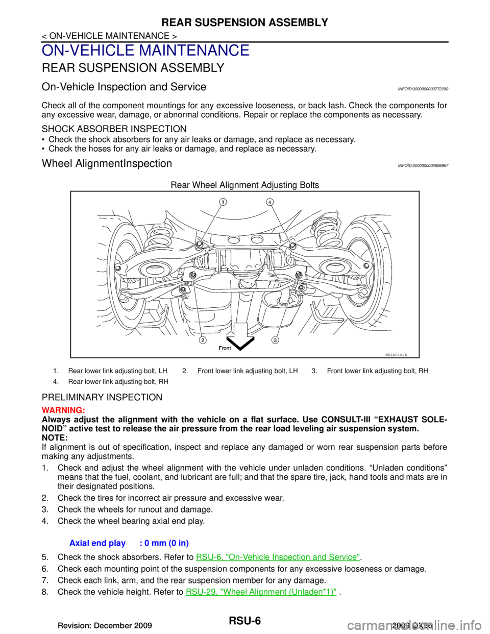
Rear Wheel Alignment Adjusting Bolts
PRELIMINARY INSPECTION
WARNING:
Always adjust the alignm ent with the vehicle on a flat su rface. Use CONSULT-III “EXHAUST SOLE-
NOID” active test to release the air pressure from the rear load leveling air suspension system.
NOTE:
If alignment is out of specificat ion, inspect and replace any damaged or worn rear suspension parts before
making any adjustments.
1. Check and adjust the wheel alignment with the vehicle under unladen conditions. “Unladen conditions”
means that the fuel, coolant, and lubricant are full; and that the spare tire, jack, hand tools and mats are in
their designated positions.
2. Check the tires for incorrect air pressure and excessive wear.
3. Check the wheels for runout and damage.
4. Check the wheel bearing axial end play.
5. Check the shock absorbers. Refer to RSU-6, "On-Vehicle Inspection and Service"
.
6. Check each mounting point of the suspension components for any excessive looseness or damage.
7. Check each link, arm, and the rear suspension member for any damage.
8. Check the vehicle height. Refer to RSU-29, "Wheel Alignment (Unladen
*1)" .
WEIA0102E
1. Rear lower link adjusting bolt, LH 2. Front lower link adjusting bolt, LH 3. Front lower link adjusting bolt, RH
4. Rear lower link adjusting bolt, RH
Axial end play : 0 mm (0 in)
Revision: December 20092009 QX56
Page 3162 of 4171
RSU-14
< REMOVAL AND INSTALLATION >
REAR SUSPENSION MEMBER
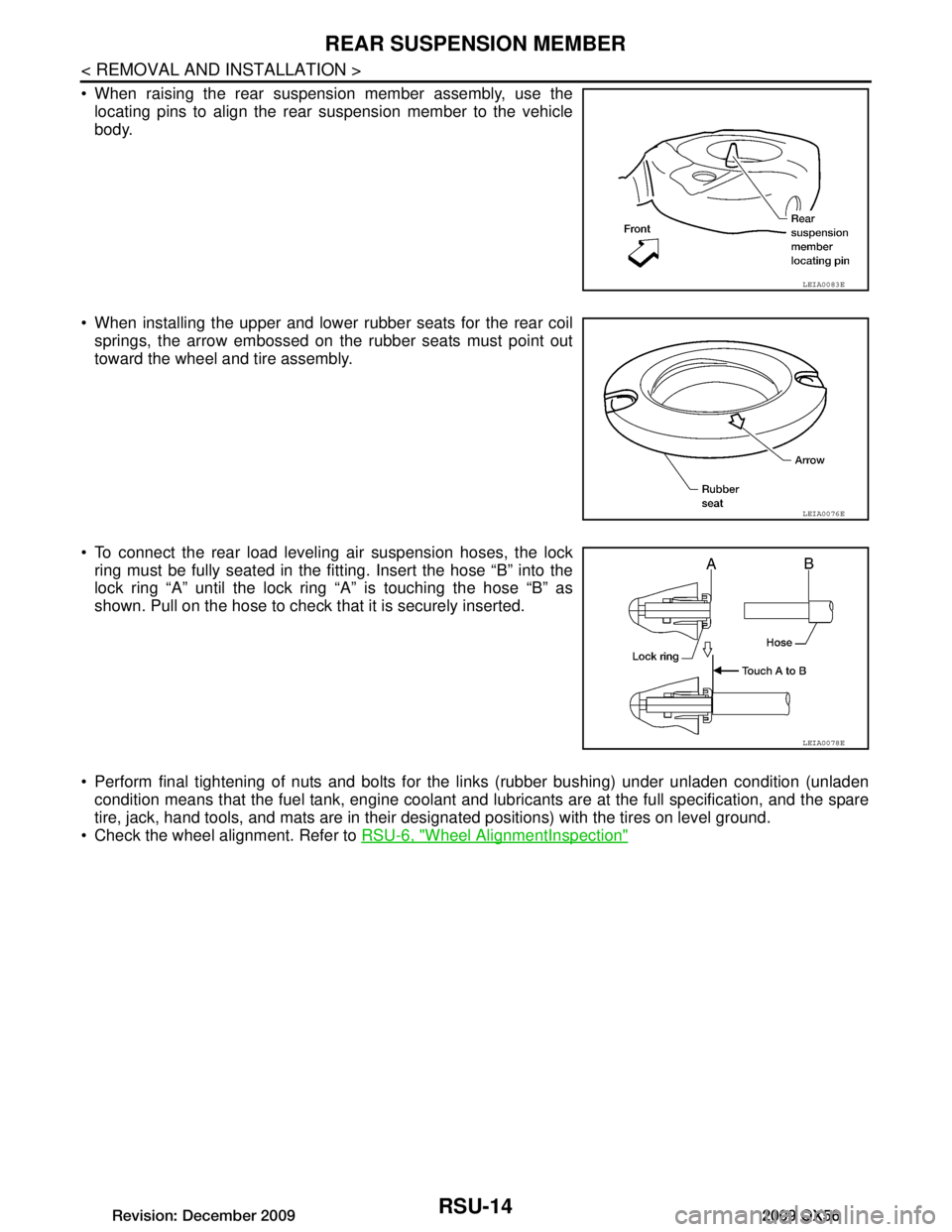
When raising the rear suspension member assembly, use thelocating pins to align the rear suspension member to the vehicle
body.
When installing the upper and lower rubber seats for the rear coil springs, the arrow embossed on the rubber seats must point out
toward the wheel and tire assembly.
To connect the rear load leveling air suspension hoses, the lock ring must be fully seated in the fitt ing. Insert the hose “B” into the
lock ring “A” until the lock ring “A” is touching the hose “B” as
shown. Pull on the hose to check that it is securely inserted.
Perform final tightening of nuts and bolts for the links (rubber bushing) under unladen condition (unladen condition means that the fuel tank, engine coolant and l ubricants are at the full specification, and the spare
tire, jack, hand tools, and mats are in their designated positions) with the tires on level ground.
Check the wheel alignment. Refer to RSU-6, "Wheel AlignmentInspection"
LEIA0083E
LEIA0076E
LEIA0078E
Revision: December 20092009 QX56
Page 3166 of 4171
RSU-18
< REMOVAL AND INSTALLATION >
SUSPENSION ARM
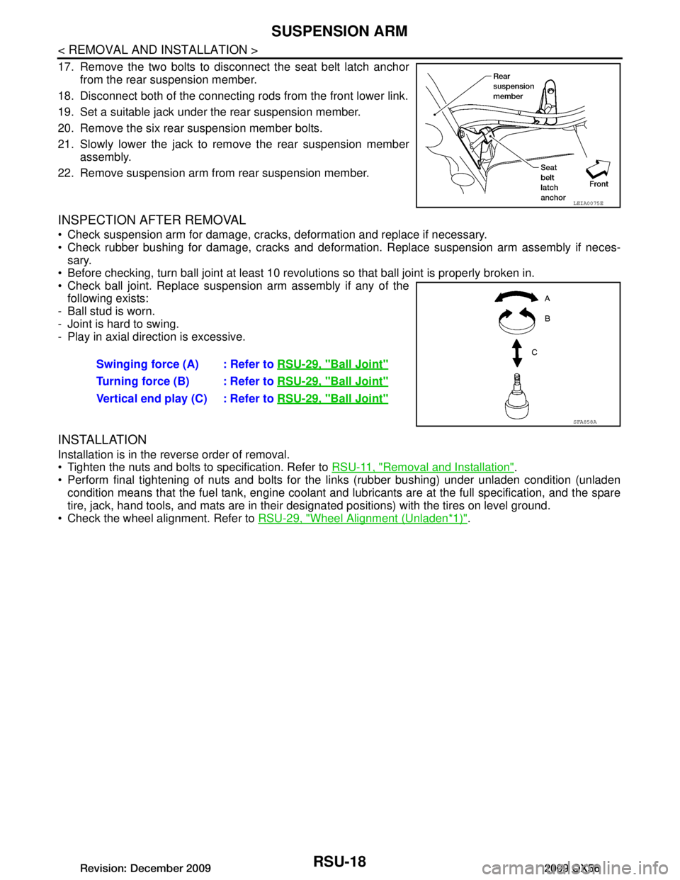
17. Remove the two bolts to disconnect the seat belt latch anchorfrom the rear suspension member.
18. Disconnect both of the connecting rods from the front lower link.
19. Set a suitable jack under the rear suspension member.
20. Remove the six rear suspension member bolts.
21. Slowly lower the jack to remove the rear suspension member assembly.
22. Remove suspension arm from rear suspension member.
INSPECTION AFTER REMOVAL
Check suspension arm for damage, cracks, deformation and replace if necessary.
Check rubber bushing for damage, cracks and deformation. Replace suspension arm assembly if neces- sary.
Before checking, turn ball joint at least 10 revolutions so that ball joint is properly broken in.
Check ball joint. Replace suspension arm assembly if any of the following exists:
- Ball stud is worn.
- Joint is hard to swing.
- Play in axial direction is excessive.
INSTALLATION
Installation is in the reverse order of removal.
Tighten the nuts and bolts to specification. Refer to RSU-11, "Removal and Installation"
.
Perform final tightening of nuts and bolts for the links (rubber bushing) under unladen condition (unladen
condition means that the fuel tank, engine coolant and l ubricants are at the full specification, and the spare
tire, jack, hand tools, and mats are in their designated positions) with the tires on level ground.
Check the wheel alignment. Refer to RSU-29, "Wheel Alignment (Unladen
*1)".
LEIA0075E
Swinging force (A) : Refer to RSU-29, "Ball Joint"
Turning force (B) : Refer to RSU-29, "Ball Joint"
Vertical end play (C) : Refer to RSU-29, "Ball Joint"
SFA858A
Revision: December 20092009 QX56
Page 3168 of 4171
RSU-20
< REMOVAL AND INSTALLATION >
FRONT LOWER LINK
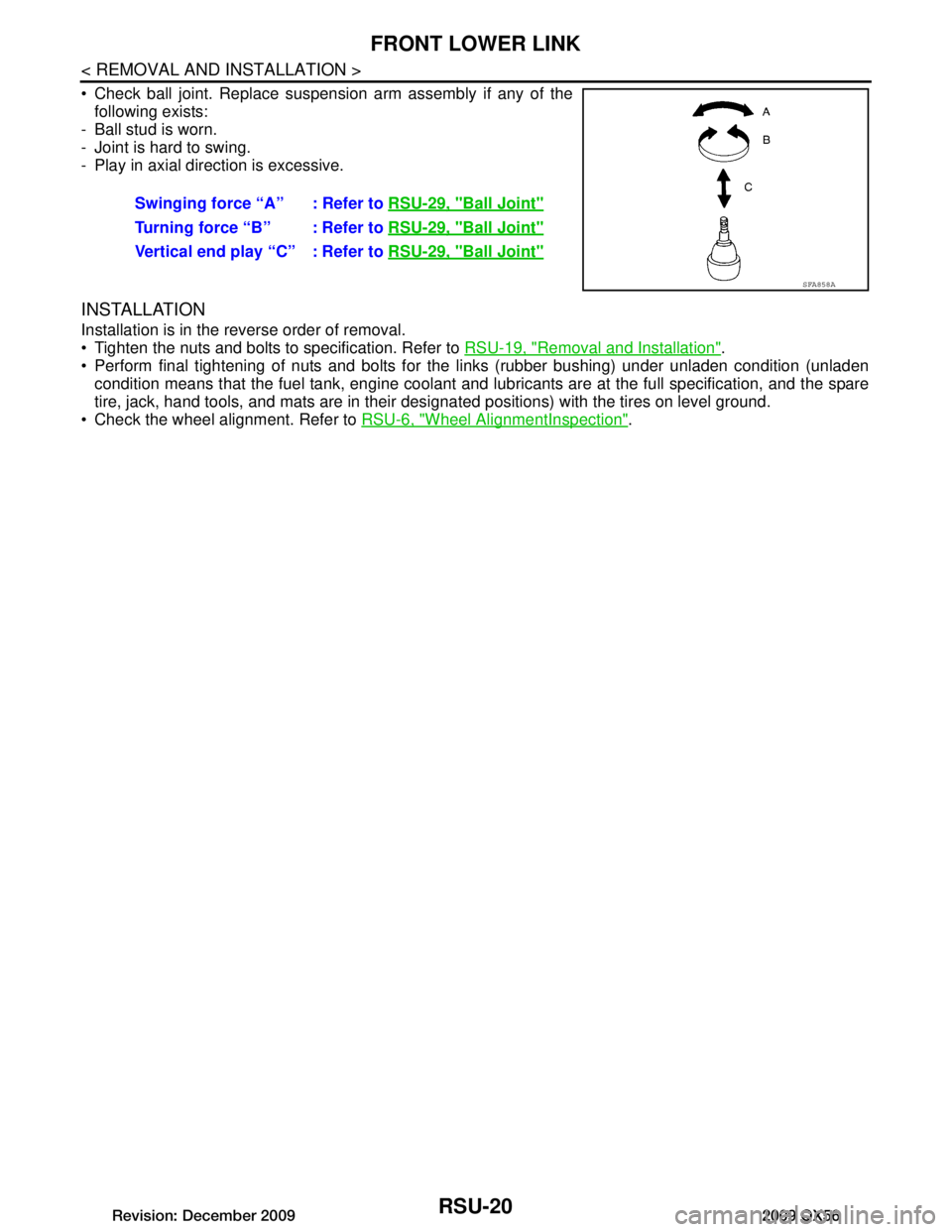
Check ball joint. Replace suspension arm assembly if any of thefollowing exists:
- Ball stud is worn.
- Joint is hard to swing.
- Play in axial direction is excessive.
INSTALLATION
Installation is in the reverse order of removal.
Tighten the nuts and bolts to specification. Refer to RSU-19, "Removal and Installation"
.
Perform final tightening of nuts and bolts for the links (rubber bushing) under unladen condition (unladen condition means that the fuel tank, engine coolant and l ubricants are at the full specification, and the spare
tire, jack, hand tools, and mats are in their designated positions) with the tires on level ground.
Check the wheel alignment. Refer to RSU-6, "Wheel AlignmentInspection"
.
Swinging force “A” : Refer to
RSU-29, "Ball Joint"
Turning force “B” : Refer to RSU-29, "Ball Joint"
Vertical end play “C” : Refer to RSU-29, "Ball Joint"
SFA858A
Revision: December 20092009 QX56
Page 3177 of 4171
SERVICE DATA AND SPECIFICATIONS (SDS)
RSU-29
< SERVICE DATA AND SPECIFICATIONS (SDS)
C
D F
G H
I
J
K L
M A
B
RSU
N
O P
SERVICE DATA AND SPECIFICATIONS (SDS)
SERVICE DATA AND SPECIFICATIONS (SDS)
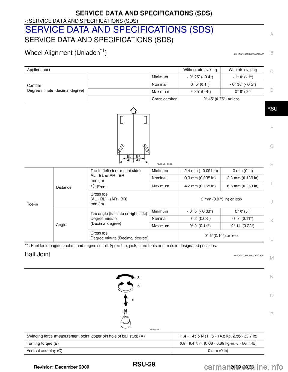
Wheel Alignment (Unladen*1)INFOID:0000000005889879
*1: Fuel tank, engine coolant and engine oil full. Spare tire, jack, hand tools and mats in designated positions.
Ball JointINFOID:0000000003772304
Applied model Without air leveling With air leveling
Camber
Degree minute (decimal degree) Minimum - 0
° 25 ′ (- 0.4 °)- 1 ° 0 ′ (- 1 °)
Nominal 0 ° 5 ′ (0.1 °)- 0 ° 30 ′ (- 0.5 °)
Maximum 0 ° 35 ′ (0.6 °)0 ° 0 ′ (0 °)
Cross camber 0 ° 45' (0.75 °) or less
To e - i n Distance
Toe-in (left side or right side)
AL - BL or AR - BR
mm (in)
:Front Minimum - 2.4 mm (- 0.094 in) 0 mm (0 in)
Nominal 0.9 mm (0.035 in) 3.3 mm (0.130 in)
Maximum 4.2 mm (0.165 in) 6.6 mm (0.260 in)
Cross toe
(AL - BL) - (AR - BR)
mm (in) 2 mm (0.079 in) or less
Angle Toe angle (left side or right side)
Degree minute
(Decimal degree) Minimum - 0
° 5' (- 0.08 °)0 ° 0' (0 °)
Nominal 0 ° 2' (0.03 °)0 ° 7' (0.11 °)
Maximum 0 ° 9' (0.14 °)0 ° 14' (0.22 °)
Cross toe
Degree minute (Decimal degree) 0
° 8' (0.14 °) or less
ALEIA0059ZZ
Swinging force (measurement point: cotter pin hole of ball stud) (A) 11.4 - 145.5 N (1.16 - 14.8 kg, 2.56 - 32.7 lb)
Turning torque (B) 0.5 - 6.4 N·m (0.06 - 0.65 kg-m, 5 - 56 in-lb)
Vertical end play (C) 0 mm (0 in)
SFA858A
Revision: December 20092009 QX56
Page 3178 of 4171
RSU-30
< SERVICE DATA AND SPECIFICATIONS (SDS)
SERVICE DATA AND SPECIFICATIONS (SDS)
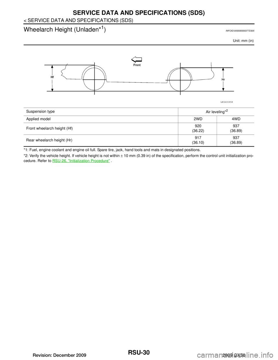
Wheelarch Height (Unladen*
1)INFOID:0000000003772305
Unit: mm (in)
*1: Fuel, engine coolant and engine oil full. Spare tire, jack, hand tools and mats in designated positions.
*2: Verify the vehicle height. If vehicle height is not within ± 10 mm (0.39 in) of the specification, perform the control unit initialization pro-
cedure. Refer to RSU-26, "Initialization Procedure"
.
Suspension type
Air leveling*
2
Applied model2WD 4WD
Front wheelarch height (Hf) 920
(36.22) 937
(36.89)
Rear wheelarch height (Hr) 917
(36.10) 937
(36.89)
LEIA0085E
Revision: December 20092009 QX56
Page 3232 of 4171
PRECAUTIONSSCS-39
< PRECAUTION >
C
DF
G H
I
J
K L
M A
B
SCS
N
O P
PRECAUTION
PRECAUTIONS
Precaution for Supplemental Restraint System (SRS) "AIR BAG" and "SEAT BELT
PRE-TENSIONER"
INFOID:0000000005867805
The Supplemental Restraint System such as “AIR BAG” and “SEAT BELT PRE-TENSIONER”, used along
with a front seat belt, helps to reduce the risk or severi ty of injury to the driver and front passenger for certain
types of collision. This system includes seat belt switch inputs and dual stage front air bag modules. The SRS
system uses the seat belt switches to determine the front air bag deployment, and may only deploy one front
air bag, depending on the severity of a collision and w hether the front occupants are belted or unbelted.
Information necessary to service the system safely is included in the SR and SB section of this Service Man-
ual.
WARNING:
• To avoid rendering the SRS inoper ative, which could increase the risk of personal injury or death in
the event of a collision which would result in air bag inflation, all maintenance must be performed by
an authorized NISSAN/INFINITI dealer.
• Improper maintenance, including in correct removal and installation of the SRS, can lead to personal
injury caused by unintentional act ivation of the system. For removal of Spiral Cable and Air Bag
Module, see the SR section.
• Do not use electrical test equipm ent on any circuit related to the SRS unless instructed to in this
Service Manual. SRS wiring harnesses can be identi fied by yellow and/or orange harnesses or har-
ness connectors.
PRECAUTIONS WHEN USING POWER TOOLS (AIR OR ELECTRIC) AND HAMMERS
WARNING:
• When working near the Airbag Diagnosis Sensor Un it or other Airbag System sensors with the Igni-
tion ON or engine running, DO NOT use air or el ectric power tools or strike near the sensor(s) with a
hammer. Heavy vibration could activate the sensor( s) and deploy the air bag(s), possibly causing
serious injury.
• When using air or electric power tools or hammers, always switch the Ignition OFF, disconnect the battery, and wait at least 3 minutes before performing any service.
Precaution for Rear SuspensionINFOID:0000000003772362
• When installing the rubber bushings, the final tightening must be done under unladen condition and with thetires on level ground. Oil will shorten the life of the rubber bushings, so wipe off any spilled oil immediately.
• Unladen condition means the fuel tank, engine coolant and lubricants are at the full specification. The spare tire, jack, hand tools, and mats are in their designated positions.
• After installing suspension components, check the wheel alignment.
• Caulking nuts are not reusable. Always use new caulking nuts for installation. New caulking nuts are pre-
oiled, do not apply any additional lubrication.
Revision: December 20092009 QX56
Page 3405 of 4171
![INFINITI QX56 2009 Factory Service Manual INTELLIGENT KEY UNITSEC-95
< ECU DIAGNOSIS > [WITH INTELLIGENT KEY SYSTEM]
C
D
E
F
G H
I
J
L
M A
B
SEC
N
O P
Fail SafeINFOID:0000000003775938
DTC Inspection Priority ChartINFOID:0000000003775939
If so INFINITI QX56 2009 Factory Service Manual INTELLIGENT KEY UNITSEC-95
< ECU DIAGNOSIS > [WITH INTELLIGENT KEY SYSTEM]
C
D
E
F
G H
I
J
L
M A
B
SEC
N
O P
Fail SafeINFOID:0000000003775938
DTC Inspection Priority ChartINFOID:0000000003775939
If so](/img/42/57031/w960_57031-3404.png)
INTELLIGENT KEY UNITSEC-95
< ECU DIAGNOSIS > [WITH INTELLIGENT KEY SYSTEM]
C
D
E
F
G H
I
J
L
M A
B
SEC
N
O P
Fail SafeINFOID:0000000003775938
DTC Inspection Priority ChartINFOID:0000000003775939
If some DTCs are displayed at the same time, perform inspections one by one based on the following priority
chart.
DTC IndexINFOID:0000000003775940
NOTE: Details of time display
• CRNT: Displays when there is a malfunction now or after returning to the normal condition until turning igni- tion switch OFF → ON again.
• 1 - 39: Displayed if any previous ma lfunction is present when current conditi on is normal. It increases like 1
→ 2 → 3...38 → 39 after returning to the normal condition whenever ignition switch OFF → ON. The counter
remains at 39 even if the number of cycles exceeds it. It is counted from 1 again when turning ignition switch
OFF → ON after returning to the normal condi tion if the malfunction is detected again.
Display contents of CONSULT-III Fail-safeCancellation
B2013: STRG COMM 1 • Inhibits steering look unlocking Erase DTC
B2552: INTELLIGENT KEY • Inhibits steering look unlocking
• Inhibits engine cranking
(BCM)
•Fuel cut (ECM) Erase DTC
B2590: NATS MALFUNCTION • Inhibits steering look unlocking
• Inhibits engine cranking
(BCM)
•Fuel cut (ECM) Erase DTC
Priority
DTC
1 • U1000: CAN COMM CIRCUIT
• U1010: CONTROL UNIT (CAN)
• B2552: INTELIGENT KEY
2 • B2013: STRG COMM 1
• B2590: NATS MALFUNCTION
CONSULT display
Detection conditionFail-safe Diagnosis
No DTC is detected.
further testing
may be required. ——
—
U1000: CAN COMM CIRCUIT Intelligent Key unit cannot receive CAN communi-
cation signal continuously for 2 seconds or more.
—Check CAN communi-
cation system.
Refer to SEC-22
U1010: CONTROL UNIT (CAN)
Intelligent Key unit detects internal CAN communi-
cation circuit malfunction.
—Replace Intelligent Key
unit.
B2013: STRG COMM 1 The ID verification result between Intelligent key
unit and steering lock solenoid are NG. Or Intelligent
Key unit cannot communicate with steering lock so-
lenoid. ×
Perform steering lock
solenoid ID registration
with CONSULT-III
B2552: INTELLIGENT KEY Intelligent Key unit internal malfunction. ×Replace Intelligent Key
unit.
B2590: NATS MALFUNCTION The ID verification result between Intelligent key
unit and BCM are NG. Or Intelligent Key unit cannot
communicate with BCM. ×
Check NATS
Refer to SEC-36
Revision: December 20092009 QX56
Page 3409 of 4171
![INFINITI QX56 2009 Factory Service Manual IPDM E/R (INTELLIGENT POWER DISTRIBUTION MODULE ENGINE ROOM)
SEC-99
< ECU DIAGNOSIS > [WITH INTELLIGENT KEY SYSTEM]
C
D
E
F
G H
I
J
L
M A
B
SEC
N
O P
Te r m i n a l Wire
color Signal name Signal
inpu INFINITI QX56 2009 Factory Service Manual IPDM E/R (INTELLIGENT POWER DISTRIBUTION MODULE ENGINE ROOM)
SEC-99
< ECU DIAGNOSIS > [WITH INTELLIGENT KEY SYSTEM]
C
D
E
F
G H
I
J
L
M A
B
SEC
N
O P
Te r m i n a l Wire
color Signal name Signal
inpu](/img/42/57031/w960_57031-3408.png)
IPDM E/R (INTELLIGENT POWER DISTRIBUTION MODULE ENGINE ROOM)
SEC-99
< ECU DIAGNOSIS > [WITH INTELLIGENT KEY SYSTEM]
C
D
E
F
G H
I
J
L
M A
B
SEC
N
O P
Te r m i n a l Wire
color Signal name Signal
input/
output Measuring condition
Reference value(Approx.)
Igni-
tion
switch Operation or condition
1 B/Y Battery power supply Input OFF —Battery voltage
2 R Battery power supply Input OFF —Battery voltage
3BRECM relay Output— Ignition switch ON or START
Battery voltage
Ignition switch OFF or ACC 0V
4W/LECM relay Output— Ignition switch ON or START
Battery voltage
Ignition switch OFF or ACC 0V
6L Throttle control motor
relay Output —Ignition switch ON or START
Battery voltage
Ignition switch OFF or ACC 0V
7 W/B ECM relay control Input — Ignition switch ON or START
0V
Ignition switch OFF or ACC Battery voltage
8 R/B Fuse 54 Output —Ignition switch ON or START
Battery voltage
Ignition switch OFF or ACC 0V
10 G Fuse 45 Output ONDaytime light system active
0V
Daytime light system inactive Battery voltage
11 Y/B A/C compressor Output ON or
START A/C switch ON or defrost A/C
switch
Battery voltage
A/C switch OFF or defrost A/C
switch 0V
12 L/W Ignition switch sup-
plied power Input —OFF or ACC
0V
ON or START Battery voltage
13 B/Y Fuel pump relay Output — Ignition switch ON or START
Battery voltage
Ignition switch OFF or ACC 0V
14 Y/R Fuse 49 Output —Ignition switch ON or START
Battery voltage
Ignition switch OFF or ACC 0V
15 LG/B Fuse 50 (VDC) Output — Ignition switch ON or START
Battery voltage
Ignition switch OFF or ACC 0V
15 GR Fuse 50 (ABS) Output — Ignition switch ON or START
Battery voltage
Ignition switch OFF or ACC 0V
16 G Fuse 51 Output —Ignition switch ON or START
Battery voltage
Ignition switch OFF or ACC 0V
17 W Fuse 55 Output —Ignition switch ON or START
Battery voltage
Ignition switch OFF or ACC 0V
19 W/R Starter motor Output START—Battery voltage
21 BR Ignition switch sup-
plied power
Input —OFF or ACC
0V
START Battery voltage
22 G Battery power supply Output OFF —Battery voltage
23 GR/W Door mirror defogger
output signal Output —When rear defogger switch is
ON
Battery voltage
When raker defogger switch is
OFF 0V
Revision: December 20092009 QX56
Page 3411 of 4171
![INFINITI QX56 2009 Factory Service Manual IPDM E/R (INTELLIGENT POWER DISTRIBUTION MODULE ENGINE ROOM)
SEC-101
< ECU DIAGNOSIS > [WITH INTELLIGENT KEY SYSTEM]
C
D
E
F
G H
I
J
L
M A
B
SEC
N
O P
41 Y/B Hood switch Input —Hood closed OFF
0V
Ho INFINITI QX56 2009 Factory Service Manual IPDM E/R (INTELLIGENT POWER DISTRIBUTION MODULE ENGINE ROOM)
SEC-101
< ECU DIAGNOSIS > [WITH INTELLIGENT KEY SYSTEM]
C
D
E
F
G H
I
J
L
M A
B
SEC
N
O P
41 Y/B Hood switch Input —Hood closed OFF
0V
Ho](/img/42/57031/w960_57031-3410.png)
IPDM E/R (INTELLIGENT POWER DISTRIBUTION MODULE ENGINE ROOM)
SEC-101
< ECU DIAGNOSIS > [WITH INTELLIGENT KEY SYSTEM]
C
D
E
F
G H
I
J
L
M A
B
SEC
N
O P
41 Y/B Hood switch Input —Hood closed OFF
0V
Hood open ON Battery voltage
42 GR Oil pressure switch Input — Engine running
Battery voltage
Engine stopped 0V
43 L/Y Wiper auto stop signal Input ON or
START Wiper switch OFF, LO, INT Battery voltage
44 BR Daytime light relay
control Input ONDaytime light system active
0V
Daytime light system inactive Battery voltage
45 G/W Horn relay control Input ON When door locks are operated
using keyfob or Intelligent Key
(OFF
→ ON)* Battery voltage
→ 0V
46 GR Fuel pump relay con-
trol
Input —Ignition switch ON or START
0V
Ignition switch OFF or ACC Battery voltage
47 O Throttle control motor
relay control
Input —Ignition switch ON or START
0V
Ignition switch OFF or ACC Battery voltage
48 B/R Starter relay (inhibit
switch) InputON or
START Selector lever in "P" or "N"
0V
Selector lever any other posi-
tion Battery voltage
49 R/L Trailer tow relay Output ON Lighting
switch must
be in the 1st
positionOFF
0V
ON Battery voltage
50 W/R Front fog lamp (LH) Output ON or
START Lighting
switch must
be in the 2nd
position
(LOW beam
is ON) and
the front fog
lamp switch OFF
0V
ON Battery voltage
51 W/R Front fog lamp (RH) Output ON or
START Lighting
switch must
be in the 2nd
position
(LOW beam
is ON) and
the front fog
lamp switch OFF
0V
ON Battery voltage
52 L LH low beam head-
lamp Output — Lighting switch in 2nd position Battery voltage
54 R/Y RH low beam head-
lamp Output — Lighting switch in 2nd position Battery voltage
55 G LH high beam head-
lamp Output —Lighting switch in 2nd position
and placed in HIGH or PASS
position Battery voltage
56 L/W RH high beam head-
lamp Output —Lighting switch in 2nd position
and placed in HIGH or PASS
position Battery voltage
57 R/L Parking, license, and
tail lamp
Output ONLighting
swi
t
ch 1st po-
sition OFF
0V
ON Battery voltage
Te r m i n a l
Wire
color Signal name Signal
input/
output Measuring condition
Reference value(Approx.)
Igni-
tion
switch Operation or condition
Revision: December 20092009 QX56