wiring INFINITI QX56 2009 Factory Service Manual
[x] Cancel search | Manufacturer: INFINITI, Model Year: 2009, Model line: QX56, Model: INFINITI QX56 2009Pages: 4171, PDF Size: 84.65 MB
Page 3630 of 4171

STR-1
ENGINE
C
DE
F
G H
I
J
K L
M
SECTION STR
A
STR
N
O P
CONTENTS
STARTING SYSTEM
PRECAUTION ....... ........................................2
PRECAUTIONS .............................................. .....2
Precaution for Supplemental Restraint System
(SRS) "AIR BAG" and "SEAT BELT PRE-TEN-
SIONER" ............................................................. ......
2
Precaution Necessary for Steering Wheel Rota-
tion After Battery Disconnect ............................... ......
2
Precaution for Power Generation Variable Voltage
Control System ..........................................................
3
PREPARATION ............................................4
PREPARATION .............................................. .....4
Special Service Tool ........................................... ......4
Commercial Service Tool ..........................................4
BASIC INSPECTION ....................................5
DIAGNOSIS AND REPAIR WORKFLOW ..... .....5
Work Flow ........................................................... ......5
FUNCTION DIAGNOSIS ...............................8
STARTING SYSTEM ...................................... .....8
System Diagram .................................................. ......8
System Description ...................................................8
Component Parts Location ........................................8
Component Description ............................................9
COMPONENT DIAGNOSIS .........................10
B TERMINAL CIRCUIT .....................................10
Description ........................................................... ....10
Diagnosis Procedure ...............................................10
S CONNECTOR CIRCUIT .................................11
Description ...............................................................11
Diagnosis Procedure ...............................................11
STARTING SYSTEM .........................................12
Wiring Diagram .................................................... ....12
SYMPTOM DIAGNOSIS ..............................17
STARTING SYSTEM .........................................17
Symptom Table ................................................... ....17
ON-VEHICLE REPAIR .................................18
STARTER MOTOR ...........................................18
Removal and Installation ..................................... ....18
SERVICE DATA AND SPECIFICATIONS
(SDS) ............... .......................................... ...
19
STARTER MOTOR ...........................................19
Starter .................................................................. ....19
Revision: December 20092009 QX56
Page 3631 of 4171

STR-2
< PRECAUTION >
PRECAUTIONS
PRECAUTION
PRECAUTIONS
Precaution for Supplemental Restraint System (SRS) "AIR BAG" and "SEAT BELT
PRE-TENSIONER"
INFOID:0000000005856238
The Supplemental Restraint System such as “A IR BAG” and “SEAT BELT PRE-TENSIONER”, used along
with a front seat belt, helps to reduce the risk or severity of injury to the driver and front passenger for certain
types of collision. This system includes seat belt switch inputs and dual stage front air bag modules. The SRS
system uses the seat belt switches to determine the front air bag deployment, and may only deploy one front
air bag, depending on the severity of a collision and w hether the front occupants are belted or unbelted.
Information necessary to service the system safely is included in the SR and SB section of this Service Man-
ual.
WARNING:
• To avoid rendering the SRS inopera tive, which could increase the risk of personal injury or death in
the event of a collision which would result in air bag inflation, all maintenance must be performed by
an authorized NISSAN/INFINITI dealer.
• Improper maintenance, including in correct removal and installation of the SRS, can lead to personal
injury caused by unintent ional activation of the system. For re moval of Spiral Cable and Air Bag
Module, see the SR section.
• Do not use electrical test equipmen t on any circuit related to the SRS unless instructed to in this
Service Manual. SRS wiring harn esses can be identified by yellow and/or orange harnesses or har-
ness connectors.
PRECAUTIONS WHEN USING POWER TOOLS (AIR OR ELECTRIC) AND HAMMERS
WARNING:
• When working near the Airbag Diagnosis Sensor Unit or other Airbag System sensors with the Igni-
tion ON or engine running, DO NOT use air or electri c power tools or strike near the sensor(s) with a
hammer. Heavy vibration could activate the sensor( s) and deploy the air bag(s), possibly causing
serious injury.
• When using air or electric power tools or hammers , always switch the Ignition OFF, disconnect the
battery, and wait at least 3 minu tes before performing any service.
Precaution Necessary for Steering W heel Rotation After Battery Disconnect
INFOID:0000000005856245
NOTE:
• This Procedure is applied only to models with Intelligent Key system and NATS (NISSAN ANTI-THEFT SYS-
TEM).
• Remove and install all control units after disconnecting both battery cables with the ignition knob in the
″LOCK ″ position.
• Always use CONSULT-III to perform self-diagnosis as a part of each function inspection after finishing work.
If DTC is detected, perform trouble diagnosis according to self-diagnostic results.
For models equipped with the Intelligent Key system and NATS, an electrically controlled steering lock mech-
anism is adopted on the key cylinder.
For this reason, if the battery is disconnected or if the battery is discharged, the steering wheel will lock and
steering wheel rotation will become impossible.
If steering wheel rotation is required when battery pow er is interrupted, follow the procedure below before
starting the repair operation.
OPERATION PROCEDURE
1. Connect both battery cables. NOTE:
Supply power using jumper cables if battery is discharged.
2. Use the Intelligent Key or mechanical key to turn the ignition switch to the ″ACC ″ position. At this time, the
steering lock will be released.
3. Disconnect both battery cables. The steering lock will remain released and the steering wheel can be rotated.
4. Perform the necessary repair operation.
Revision: December 20092009 QX56
Page 3641 of 4171

STR-12
< COMPONENT DIAGNOSIS >
STARTING SYSTEM
STARTING SYSTEM
Wiring DiagramINFOID:0000000003771796
ABBWA0004GB
Revision: December 20092009 QX56
Page 3651 of 4171

TM-3
CEF
G H
I
J
K L
M A
B
TM
N
O P
Diagnosis Procedure ...........................................
....
78
P1752 INPUT CLUTCH SOLENOID ..................80
Description .......................................................... ....80
CONSULT-III Reference Value in Data Monitor
Mode ................................................................... ....
80
On Board Diagnosis Logic ......................................80
Possible Cause .......................................................80
DTC Confirmation Procedure ..................................80
Diagnosis Procedure ...............................................80
P1757 FRONT BRAKE SOLENOID ...................82
Description .......................................................... ....82
CONSULT-III Reference Value in Data Monitor
Mode ................................................................... ....
82
On Board Diagnosis Logic ......................................82
Possible Cause .......................................................82
DTC Confirmation Procedure ..................................82
Diagnosis Procedure ...............................................82
P1762 DIRECT CLUTCH SOLENOID ................84
Description .......................................................... ....84
CONSULT-III Reference Value in Data Monitor
Mode ................................................................... ....
84
On Board Diagnosis Logic ......................................84
Possible Cause .......................................................84
DTC Confirmation Procedure ..................................84
Diagnosis Procedure ...............................................84
P1767 HIGH AND LOW REVERSE CLUTCH
SOLENOID .........................................................
86
Description .......................................................... ....86
CONSULT-III Reference Value in Data Monitor
Mode ................................................................... ....
86
On Board Diagnosis Logic ......................................86
Possible Cause .......................................................86
DTC Confirmation Procedure ..................................86
Diagnosis Procedure ...............................................86
P1772 LOW COAST BRAKE SOLENOID .........88
Description .......................................................... ....88
CONSULT-III Reference Value in Data Monitor
Mode ................................................................... ....
88
On Board Diagnosis Logic ......................................88
Possible Cause .......................................................88
DTC Confirmation Procedure ..................................88
Diagnosis Procedure ...............................................88
P1774 LOW COAST BRAKE SOLENOID .........90
Description .......................................................... ....90
CONSULT-III Reference Value in Data Monitor
Mode ................................................................... ....
90
On Board Diagnosis Logic ......................................90
Possible Cause .......................................................90
DTC Confirmation Procedure ..................................90
Diagnosis Procedure ...............................................90
MAIN POWER SUPPLY AND GROUND CIR-
CUIT ....................................................................
92
Diagnosis Procedure ........................................... ....92
CLOSED THROTTLE POSITION AND WIDE
OPEN THROTTLE POSITION CIRCUIT ...........
94
CONSULT-III Reference Value in Data Monitor
Mode .................................................................... ....
94
Diagnosis Procedure ...............................................94
BRAKE SIGNAL CIRCUIT ................................95
CONSULT-III Reference Value in Data Monitor
Mode .................................................................... ....
95
Diagnosis Procedure ...............................................95
TOW MODE SWITCH .......................................96
Description ...............................................................96
Diagnosis Procedure ...............................................96
A/T SHIFT LOCK SYSTEM ...............................97
Wiring Diagram - A/T Shift Lock System .................97
Terminals And Reference Values ..........................101
Component Description .........................................101
ECU DIAGNOSIS .......................................104
TCM .................................................................104
Reference Value .................................................. ..104
Wiring Diagram — A/T CONTROL SYSTEM — .. ..106
Fail-Safe .............................................................. ..115
DTC Inspection Priority Chart ................................117
DTC No. Index .......................................................117
DTC Alphabetical Index .........................................118
SYMPTOM DIAGNOSIS ............................119
SYSTEM SYMPTOM .......................................119
A/T Check Indicator Lamp Does Not Come On ... ..119
Engine Cannot Be Started in "P" or "N" Position ...119
In "P" Position, Vehicle Moves When Pushed .......120
In "N" Position, Vehicle Moves ..............................120
Large Shock("N" to "D" Position) ...........................122
Vehicle Does Not Creep Backward in "R" Position ..124
Vehicle Does Not Creep Forward in "D" Position ..126
Vehicle Cannot Be Started from D1 ......................129
A/T Does Not Shift: D1ÆD2 ..................................131
A/T Does Not Shift: D2ÆD3 ..................................132
A/T Does Not Shift: D3ÆD4 ..................................134
A/T Does Not Shift: D4ÆD5 ..................................136
A/T Does Not Perform Lock-up .............................138
A/T Does Not Hold Lock-up Condition ...................140
Lock-up Is Not Released .......................................141
Engine Speed Does Not Return to Idle .................142
A/T Does Not Shift: 5GR Æ 4GR ..........................143
A/T Does Not Shift: 4GR Æ 3GR ..........................145
A/T Does Not Shift: 3GR Æ 2GR ..........................147
A/T Does Not Shift: 2GR Æ 1GR ..........................148
Vehicle Does Not Decelerate By Engine Brake .....150
Symptom Table .....................................................152
PRECAUTION ............................................174
PRECAUTIONS ...............................................174
Revision: December 20092009 QX56
Page 3653 of 4171

DIAGNOSIS AND REPAIR WORKFLOWTM-5
< BASIC INSPECTION >
CEF
G H
I
J
K L
M A
B
TM
N
O P
BASIC INSPECTION
DIAGNOSIS AND REPAIR WORKFLOW
Work FlowINFOID:0000000003771803
INTRODUCTION
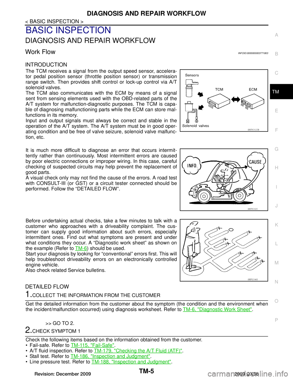
The TCM receives a signal from the output speed sensor, accelera-
tor pedal position sensor (throttle position sensor) or transmission
range switch. Then provides shift c ontrol or lock-up control via A/T
solenoid valves.
The TCM also communicates with the ECM by means of a signal
sent from sensing elements used wit h the OBD-related parts of the
A/T system for malfunction-diagnostic purposes. The TCM is capa-
ble of diagnosing malfunctioning parts while the ECM can store mal-
functions in its memory.
Input and output signals must always be correct and stable in the
operation of the A/T system. T he A/T system must be in good oper-
ating condition and be free of valve seizure, solenoid valve malfunc-
tion, etc.
It is much more difficult to diagnose an error that occurs intermit-
tently rather than continuously. Most intermittent errors are caused
by poor electric connections or impr oper wiring. In this case, careful
checking of suspected circuits may help prevent the replacement of
good parts.
A visual check only may not find t he cause of the errors. A road test
with CONSULT-III (or GST) or a circuit tester connected should be
performed. Follow the “DETAILED FLOW”.
Before undertaking actual checks, take a few minutes to talk with a
customer who approaches with a driveability complaint. The cus-
tomer can supply good information about such errors, especially
intermittent ones. Find out what symptoms are present and under
what conditions they occur. A “Diagnostic work sheet” as shown on
the example (Refer to TM-6
) should be used.
Start your diagnosis by looking for “conventional” errors first. This will
help troubleshoot driveability errors on an electronically controlled
engine vehicle.
Also check related Service bulletins.
DETAILED FLOW
1.COLLECT THE INFORMATION FROM THE CUSTOMER
Get the detailed information from the customer about the symptom (the condition and the environment when
the incident/malfunction occurred) using diagnosis worksheet. Refer to TM-6, "Diagnostic Work Sheet"
.
>> GO TO 2.
2.CHECK SYMPTOM 1
Check the following items based on the in formation obtained from the customer.
Fail-safe. Refer to TM-115, "Fail-Safe"
.
A/T fluid inspection. Refer to TM-179, "Checking the A/T Fluid (ATF)"
.
Stall test. Refer to TM-186, "Inspection and Judgment"
.
Line pressure test. Refer to TM-188, "Inspection and Judgment"
.
SAT631IB
SAT632I
SEF234G
Revision: December 20092009 QX56
Page 3669 of 4171

A/T CONTROL SYSTEMTM-21
< FUNCTION DIAGNOSIS >
CEF
G H
I
J
K L
M A
B
TM
N
O P
CONTROL SYSTEM DIAGRAM
CAN CommunicationINFOID:0000000003771809
SYSTEM DESCRIPTION
CAN (Controller Area Network) is a serial communication li ne for real time application. It is an on-vehicle mul-
tiplex communication line with high data communication speed and excellent error detection ability. Many elec-
tronic control units are equipped onto a vehicle, and each control unit shares information and links with other
control units during operation (not independent). In CAN communication, control units are connected with 2
communication lines (CAN H line, CAN L line) allowing a high rate of information transmission with less wiring.
Each control unit transmits/receives data but selectively reads required data only. For details, refer to LAN-4,
"System Description".
SENSORS (or SIGNALS)
⇒TCM
⇒ACTUATORS
Transmission range switch
Accelerator pedal position sensor
Closed throttle position signal
Wide open throttle position signal
Engine speed signal
A/T fluid temperature sensor
Output speed sensor
Vehicle speed signal
Stop lamp switch signal
Input speed sensor
1st position switch signal
4th position switch signal
ATF pressure switch 2 signal
Tow mode switch signal Shift control
Line pressure control
Lock-up control
Engine brake control
Timing control
Fail-safe control
Self-diagnosis
CONSULT-III co
mmunication
line
Duet-EA control
CAN system Input clutch solenoid valve
Direct clutch solenoid valve
Front brake solenoid valve
High and low reverse clutch sole-
noid valve
Low coast brake solenoid valve
Torque converter clutch solenoid
valve
Line pressure solenoid valve
A/T CHECK indicator lamp
Starter relay
Back-up lamp relay
JSDIA1315GB
Revision: December 20092009 QX56
Page 3687 of 4171

U1000 CAN COMM CIRCUITTM-39
< COMPONENT DIAGNOSIS >
CEF
G H
I
J
K L
M A
B
TM
N
O P
COMPONENT DIAGNOSIS
U1000 CAN COMM CIRCUIT
DescriptionINFOID:0000000003771825
CAN (Controller Area Network) is a serial communication li ne for real time application. It is an on-vehicle mul-
tiplex communication line with high data communica tion speed and excellent malfunction detection ability.
Many electronic control units are equipped onto a vehicl e, and each control unit shares information and links
with other control units during operation (not independent ). In CAN communication, control units are con-
nected with 2 communication lines (CAN H line, CAN L li ne) allowing a high rate of information transmission
with less wiring. Each control unit transmits/recei ves data but selectively reads required data only.
On Board Diagnosis LogicINFOID:0000000003771826
This is an OBD-III self-diagnostic item.
Diagnostic trouble code “U1000” with CONSULT-III is detected when TCM cannot communicate to other
control units.
Possible CauseINFOID:0000000003771827
Harness or connectors
(CAN communication line is open or shorted.)
DTC Confirmation ProcedureINFOID:0000000003771828
NOTE:
If “DTC Confirmation Procedure” has been previously performed, always turn ignition switch “OFF”
and wait at least 10 seconds before performing the next test.
After the repair, perform the following procedure to confirm the malfunction is eliminated.
WITH CONSULT-III
1. Turn ignition switch “ON”. (Do not start engine.)
2. Select “DATA MONITOR” mode for “ENGINE” with CONSULT-III.
3. Start engine and wait for at least 6 seconds.
4. If DTC is detected, go to TM-39, "Diagnosis Procedure"
.
WITH GST
Follow the procedure “WITH CONSULT-III”.
Diagnosis ProcedureINFOID:0000000003771829
1.CHECK CAN COMMUNICATION CIRCUIT
With CONSULT-III1. Turn ignition switch “ON” and start engine.
2. Select “SELF-DIAG RESULTS” mode for “TRANSMISSION” with CONSULT-III.
Is any malfunction of the
“CAN COMM CIRCUIT” indicated?
YES >> Go to LAN section. Refer to LAN-14, "Trouble Diagnosis Flow Chart".
NO >> INSPECTION END
Revision: December 20092009 QX56
Page 3745 of 4171

A/T SHIFT LOCK SYSTEMTM-97
< COMPONENT DIAGNOSIS >
CEF
G H
I
J
K L
M A
B
TM
N
O P
A/T SHIFT LOCK SYSTEM
Wiring Diagram - A/ T Shift Lock SystemINFOID:0000000003771982
AADWA0090GB
Revision: December 20092009 QX56
Page 3754 of 4171

TM-106
< ECU DIAGNOSIS >
TCM
Wiring Diagram —A/T CONTROL SYSTEM —
INFOID:0000000003771986
AADWA0088GB
Revision: December 20092009 QX56
Page 3822 of 4171

TM-174
< PRECAUTION >
PRECAUTIONS
PRECAUTION
PRECAUTIONS
Precaution for Supplemental Restraint System (SRS) "AIR BAG" and "SEAT BELT
PRE-TENSIONER"
INFOID:0000000005880175
The Supplemental Restraint System such as “A IR BAG” and “SEAT BELT PRE-TENSIONER”, used along
with a front seat belt, helps to reduce the risk or severi ty of injury to the driver and front passenger for certain
types of collision. This system includes seat belt switch inputs and dual stage front air bag modules. The SRS
system uses the seat belt switches to determine the front air bag deployment, and may only deploy one front
air bag, depending on the severity of a collision and w hether the front occupants are belted or unbelted.
Information necessary to service the system safely is included in the SR and SB section of this Service Man-
ual.
WARNING:
To avoid rendering the SRS inopera tive, which could increase the risk of personal injury or death in
the event of a collision which would result in air bag inflation, all maintenance must be performed by
an authorized NISS AN/INFINITI dealer.
Improper maintenance, including in correct removal and installation of the SRS, can lead to personal
injury caused by unintent ional activation of the system. For re moval of Spiral Cable and Air Bag
Module, see the SR section.
Do not use electrical test equipmen t on any circuit related to the SRS unless instructed to in this
Service Manual. SRS wiring harnesses can be identi fied by yellow and/or orange harnesses or har-
ness connectors.
PRECAUTIONS WHEN USING POWER TOOLS (AIR OR ELECTRIC) AND HAMMERS
WARNING:
When working near the Airbag Diagnosis Sensor Unit or other Airbag System sensors with the Igni-
tion ON or engine running, DO NOT use air or electri c power tools or strike near the sensor(s) with a
hammer. Heavy vibration could activate the sensor( s) and deploy the air bag(s), possibly causing
serious injury.
When using air or electric power tools or hammers , always switch the Ignition OFF, disconnect the
battery, and wait at least 3 minu tes before performing any service.
Precaution Necessary for Steering W heel Rotation After Battery Disconnect
INFOID:0000000005880176
NOTE:
This Procedure is applied only to models with Intelli gent Key system and NATS (NISSAN ANTI-THEFT SYS-
TEM).
Remove and install all control units after disconnecting both battery cables with the ignition knob in the
″LOCK ″ position.
Always use CONSULT-III to perform self-diagnosis as a part of each function inspection after finishing work.
If DTC is detected, perform trouble diagnosis according to self-diagnostic results.
For models equipped with the Intelligent Key system and NATS, an electrically controlled steering lock mech-
anism is adopted on the key cylinder.
For this reason, if the battery is disconnected or if the battery is discharged, the steering wheel will lock and
steering wheel rotation will become impossible.
If steering wheel rotation is required when battery pow er is interrupted, follow the procedure below before
starting the repair operation.
OPERATION PROCEDURE
1. Connect both battery cables. NOTE:
Supply power using jumper cables if battery is discharged.
2. Use the Intelligent Key or mechanical key to turn the ignition switch to the ″ACC ″ position. At this time, the
steering lock will be released.
3. Disconnect both battery cables. The steering lock will remain released and the steering wheel can be
rotated.
4. Perform the necessary repair operation.
Revision: December 20092009 QX56