window INFINITI QX56 2009 Factory Service Manual
[x] Cancel search | Manufacturer: INFINITI, Model Year: 2009, Model line: QX56, Model: INFINITI QX56 2009Pages: 4171, PDF Size: 84.65 MB
Page 1 of 4171

A
B
C
D
E
F
G
H
I
J
K
L
M
N
P
O
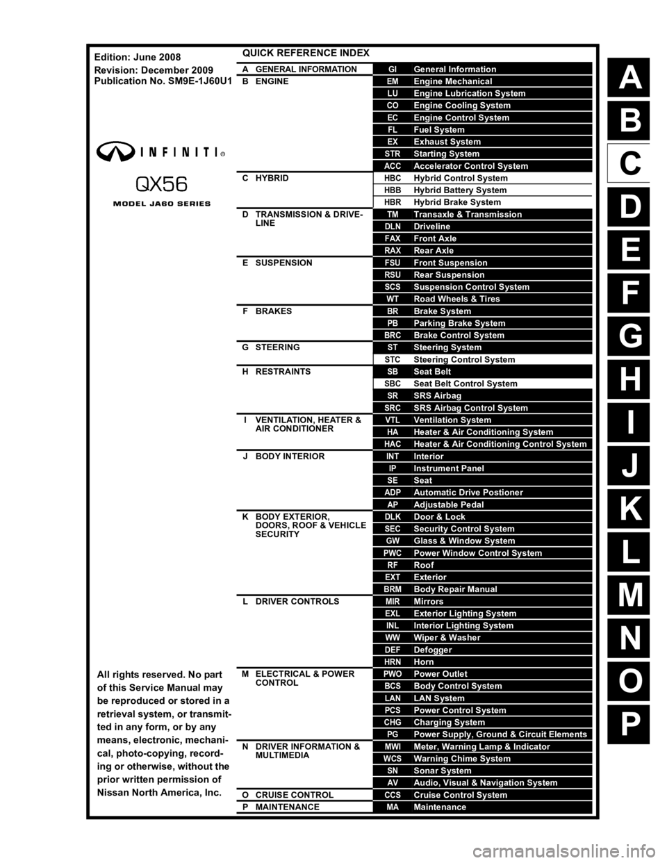
QUICK REFERENCE INDEX
AGENERAL INFORMATIONGIGeneral Information
BENGINEEMEngine Mechanical
LUEngine Lubrication System
COEngine Cooling System
ECEngine Control System
FLFuel System
EXExhaust System
STRStarting System
ACCAccelerator Control System
CHYBRIDHBCHybrid Control System
HBBHybrid Battery System
HBRHybrid Brake System
DTRANSMISSION & DRIVE-
LINETMTransaxle & Transmission
DLNDriveline
FAXFront Axle
RAXRear Axle
ESUSPENSIONFSUFront Suspension
RSURear Suspension
SCSSuspension Control System
WTRoad Wheels & Tires
FBRAKESBRBrake System
PBParking Brake System
BRCBrake Control System
GSTEERINGSTSteering System
STCSteering Control System
HRESTRAINTSSBSeat Belt
SBCSeat Belt Control System
SRSRS Airbag
SRCSRS Airbag Control System
IVENTILATION, HEATER &
AIR CONDITIONERVTLVentilation System
HAHeater & Air Conditioning System
HACHeater & Air Conditioning Control System
JBODY INTERIORINTInterior
IPInstrument Panel
SESeat
ADPAutomatic Drive Postioner
APAdjustable Pedal
KBODY EXTERIOR,
DOORS, ROOF & VEHICLE
SECURITYDLKDoor & Lock
SECSecurity Control System
GWGlass & Window System
PWCPower Window Control System
RFRoof
EXTExterior
BRMBody Repair Manual
LDRIVER CONTROLSMIRMirrors
EXLExterior Lighting System
INLInterior Lighting System
WWWiper & Washer
DEFDefogger
HRNHorn
MELECTRICAL & POWER
CONTROLPWOPower Outlet
BCSBody Control System
LANLAN System
PCSPower Control System
CHGCharging System
PGPower Supply, Ground & Circuit Elements
NDRIVER INFORMATION &
MULTIMEDIAMWIMeter, Warning Lamp & Indicator
WCSWarning Chime System
SNSonar System
AVAudio, Visual & Navigation System
OCRUISE CONTROLCCSCruise Control System
PMAINTENANCEMAMaintenance
All rights reserved. No part
of this Service Manual may
be reproduced or stored in a
retrieval system, or transmit-
ted in any form, or by any
means, electronic, mechani-
cal, photo-copying, record-
ing or otherwise, without the
prior written permission of
Nissan North America, Inc.
Edition: June 2008
Revision: December 2009
Publication No. SM9
E-1J60U1
Page 161 of 4171

BCM (BODY CONTROL MODULE)ADP-147
< ECU DIAGNOSIS >
C
DE
F
G H
I
K L
M A
B
ADP
N
O P
HEADLAMP SW1 Headlamp switch OFF OFF
Headlamp switch 1st ON
HEADLAMP SW2 Headlamp switch OFF OFF
Headlamp switch 1st ON
HI BEAM SW High beam switch OFF OFF
High beam switch HI ON
H/L WASH SW NOTE:
The item is indicated, but not monitored OFF
IGN ON SW Ignition switch OFF or ACC OFF
Ignition switch ON ON
IGN SW CAN Ignition switch OFF or ACC OFF
Ignition switch ON ON
INT VOLUME Wiper intermittent dial is in a dial position 1 - 7 1 - 7
I-KEY LOCK LOCK button of Intelligent Key is not pressed OFF
LOCK button of Intelligent Key is pressed ON
I-KEY UNLOCK UNLOCK button of Intelligent Key is not pressed OFF
UNLOCK button of Intelligent Key is pressed ON
KEY ON SW Mechanical key is removed from key cylinder OFF
Mechanical key is inserted to key cylinder ON
OIL PRESS SW Ignition switch OFF or ACC
Engine running
OFF
Ignition switch ON ON
PASSING SW Other than lighting switch PASS OFF
Lighting switch PASS ON
REAR DEF SW Rear window defogger switch OFF OFF
Rear window defogger switch ON ON
RKE LOCK AND UN-
LOCK NOTE:
The item is indicated, but not monitored OFF
ON
RR WASHER SW Rear washer switch OFF OFF
Rear washer switch ON ON
RR WIPER INT Rear wiper switch OFF OFF
Rear wiper switch INT ON
RR WIPER ON Rear wiper switch OFF OFF
Rear wiper switch ON ON
RR WIPER STOP Rear wiper stop position OFF
Other than rear wiper stop position ON
TAIL LAMP SW Lighting switch OFF OFF
Lighting switch 1ST ON
TRNK OPNR SW When back door opener switch is not pressed OFF
When back door opener switch is pressed ON
TURN SIGNAL L Turn signal switch OFF OFF
Turn signal switch LH ON
TURN SIGNAL R Turn signal switch OFF OFF
Turn signal switch RH ON
VEHICLE SPEED While driving Equiv alent to speedometer reading
Monitor Item Condition Value/Status
Revision: December 20092009 QX56
Page 163 of 4171

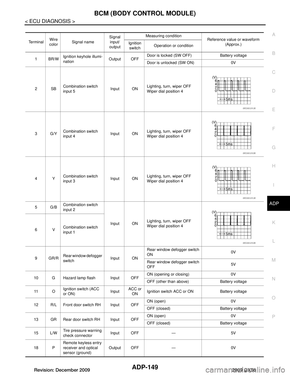
BCM (BODY CONTROL MODULE)ADP-149
< ECU DIAGNOSIS >
C
DE
F
G H
I
K L
M A
B
ADP
N
O P
Te r m i n a l Wire
color Signal name Signal
input/
output Measuring condition
Reference value or waveform
(Approx.)
Ignition
switch Operation or condition
1BR/W Ignition keyhole illumi-
nation Output OFFDoor is locked (SW OFF) Battery voltage
Door is unlocked (SW ON) 0V
2SB Combination switch
input 5 Input ON
Lighting, turn, wiper OFF
Wiper dial position 4
3G/Y Combination switch
input 4 Input ONLighting, turn, wiper OFF
Wiper dial position 4
4Y Combination switch
input 3 Input ON
Lighting, turn, wiper OFF
Wiper dial position 4
5G/B Combination switch
input 2
Input ONLighting, turn, wiper OFF
Wiper dial position 4
6V Combination switch
input 1
9GR/R Rear window defogger
switch
Input ONRear window defogger switch
ON
0V
Rear window defogger switch
OFF 5V
10 G Hazard lamp flash Input OFF ON (opening or closing) 0V
OFF (other than above) Battery voltage
11 O Ignition switch (ACC
or ON)
InputACC or
ON Ignition switch ACC or ON Battery voltage
12 R/L Front door switch RH Input OFF ON (open) 0V
OFF (closed) Battery voltage
13 GR Rear door switch RH Input OFF ON (open) 0V
OFF (closed) Battery voltage
15 L/W Tire pressure warning
check connector
Input OFF — 5V
18 P Remote keyless entry
receiver and optical
sensor (ground)
Output OFF — 0V
SKIA5291E
SKIA5292E
SKIA5291E
SKIA5292E
Revision: December 20092009 QX56
Page 164 of 4171

ADP-150
< ECU DIAGNOSIS >
BCM (BODY CONTROL MODULE)
19 V/WRemote keyless entry
receiver (power sup-
ply) Output OFF Ignition switch OFF
20 G/W Remote keyless entry
receiver (signal) Input OFFStand-by (keyfob buttons re-
leased)
When remote keyless entry
receiver receives signal from
keyfob (keyfob buttons
pressed)
21 G NATS antenna amp. Input OFF
→
ON Ignition switch (OFF
→ ON) Just after turning ignition switch
ON: Pointer of tester should
move for approx. 1 second, then return to battery voltage.
22 W/V BUS — — Ignition switch ON or power
window timer operates
23 G/O Security indicator
lamp Output OFF
Goes OFF
→ illuminates (Ev-
ery 2.4 seconds) Battery voltage
→ 0V
25 BR NATS antenna amp. Input OFF
→
ON Ignition switch (OFF
→ ON) Just after turning ignition switch
ON: Pointer of tester should
move for approx. 1 second, then return to battery voltage.
26 Y/L Rear wiper auto stop
switch 2 Input ONRise up position (rear wiper
arm on stopper)
0V
A Position (full clockwise stop
position) 0V
Forward sweep (counterclock-
wise direction) Fluctuating
B Position (full counterclock-
wise stop position) Battery voltage
Reverse sweep (clockwise di-
rection) Fluctuating
27 W/R Compressor ON sig-
nal Input ONA/C switch OFF 5V
A/C switch ON 0V
Te r m i n a l
Wire
color Signal name Signal
input/
output Measuring condition
Reference value or waveform
(Approx.)
Ignition
switch Operation or condition
LIIA1893E
LIIA1894E
LIIA1895E
PIIA2344E
Revision: December 20092009 QX56
Page 167 of 4171

BCM (BODY CONTROL MODULE)ADP-153
< ECU DIAGNOSIS >
C
DE
F
G H
I
K L
M A
B
ADP
N
O P
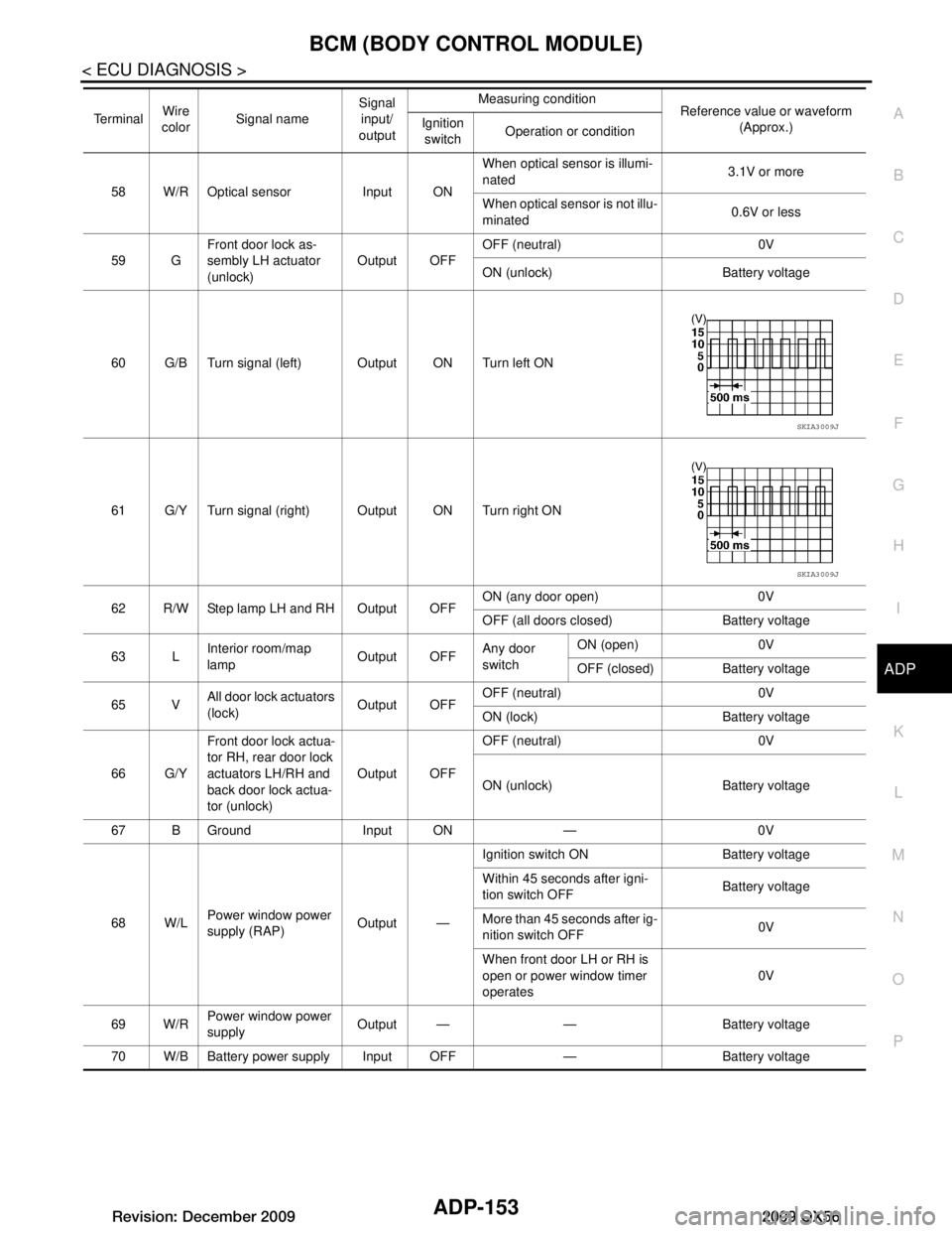
58 W/R Optical sensor Input ON When optical sensor is illumi-
nated
3.1V or more
When optical sensor is not illu-
minated 0.6V or less
59 G Front door lock as-
sembly LH actuator
(unlock) Output OFF
OFF (neutral) 0V
ON (unlock) Battery voltage
60 G/B Turn signal (left) Output ON Turn left ON
61 G/Y Turn signal (right) Output ON Turn right ON
62 R/W Step lamp LH and RH Output OFF ON (any door open) 0V
OFF (all doors closed) Battery voltage
63 L Interior room/map
lamp Output OFFAny door
switchON (open) 0V
OFF (closed) Battery voltage
65 V All door lock actuators
(lock) Output OFFOFF (neutral) 0V
ON (lock) Battery voltage
66 G/Y Front door lock actua-
tor RH, rear door lock
actuators LH/RH and
back door lock actua-
tor (unlock) Output OFF
OFF (neutral) 0V
ON (unlock) Battery voltage
67 B Ground Input ON — 0V
68 W/L Power window power
supply (RAP) Output —Ignition switch ON Battery voltage
Within 45 seconds after igni-
tion switch OFF
Battery voltage
More than 45 seconds after ig-
nition switch OFF 0V
When front door LH or RH is
open or power window timer
operates 0V
69 W/R Power window power
supply
Output — — Battery voltage
70 W/B Battery power supply Input OFF — Battery voltage
Te r m i n a l
Wire
color Signal name Signal
input/
output Measuring condition
Reference value or waveform
(Approx.)
Ignition
switch Operation or condition
SKIA3009J
SKIA3009J
Revision: December 20092009 QX56
Page 182 of 4171

ADP-168
< ON-VEHICLE REPAIR >
DOOR MIRROR REMOTE CONTROL SWITCH
DOOR MIRROR REMOTE CONTROL SWITCH
Removal and InstallationINFOID:0000000004055982
The door mirror remote control switch is part of the power window switch assembly. Refer to INT-11, "Removal
and Installation" for removal and installation of door mirror remote control switch.
Revision: December 20092009 QX56
Page 190 of 4171

AV-4
STEERING SWITCH ........................................178
Removal and Installation ..................................... ..178
REAR AUDIO REMOTE CONTROL UNIT ......179
Removal and Installation ..................................... ..179
DVD ENTERTAINMENT SYSTEM ..................180
Removal and Installation ..................................... ..180
BOSE SPEAKER AMP ....................................181
Removal and Installation ..................................... ..181
AUDIO ANTENNA ...........................................182
Location of Antennas ........................................... ..182
Window Antenna Repair ........................................182
SATELLITE RADIO ANTENNA .......................184
Removal and Installation .......................................184
GPS ANTENNA .............................................. ..185
Removal and Installation .......................................185
MICROPHONE ............................................... ..186
Removal and Installation .......................................186
REAR VIEW CAMERA .....................................187
Removal and Installation .......................................187
REAR VIEW CAMERA CONTROL UNIT ....... ..188
Removal and Installation .......................................188
Revision: December 20092009 QX56
Page 196 of 4171
![INFINITI QX56 2009 Factory Service Manual AV-10
< FUNCTION DIAGNOSIS >[AUDIO SYSTEM]
AUDIO SYSTEM
The audio system consists of the following components
• AV control unit
• Display unit
• BOSE speaker amp.
• Window antenna
• Steering INFINITI QX56 2009 Factory Service Manual AV-10
< FUNCTION DIAGNOSIS >[AUDIO SYSTEM]
AUDIO SYSTEM
The audio system consists of the following components
• AV control unit
• Display unit
• BOSE speaker amp.
• Window antenna
• Steering](/img/42/57031/w960_57031-195.png)
AV-10
< FUNCTION DIAGNOSIS >[AUDIO SYSTEM]
AUDIO SYSTEM
The audio system consists of the following components
• AV control unit
• Display unit
• BOSE speaker amp.
• Window antenna
• Steering wheel audio control switches
• A/C and AV switch assembly
• Rear audio and remote control unit
• Front door speakers
• Front tweeters
• Center speaker
• Rear door speakers
• Rear door tweeters
• Back door speakers
• Subwoofer
When the audio system is on, radio signals are receiv
ed by the window antenna. The AV control unit then
sends audio signals to the BOSE speaker amp. The BO SE speaker amp. amplifies the audio signals before
sending them to the front door speakers, front tweeters, center speaker, rear door speakers, rear door tweet-
ers, back door speakers and the subwoofer.
Refer to Owner's Manual for audio system operating instructions.
SATELLITE RADIO SYSTEM
The satellite radio system consists of the following components
• Satellite antenna
• AV control unit
When the satellite radio system is on, radio signals are supplied to the AV contro l unit from the satellite
antenna. The AV control unit then sends audio signals to the BOSE speaker amp.
Refer to Owner's Manual for satellite radio system operating instructions.
SPEED SENSITIVE VOLUME SYSTEM
Volume level of this system goes up and down automatically in proportion to the vehicle speed. The control
level can be selected by the customer. Refer to Owner's Manual for operating instructions.
Revision: December 20092009 QX56
Page 300 of 4171
![INFINITI QX56 2009 Factory Service Manual AV-114
< ECU DIAGNOSIS >[AUDIO SYSTEM]
AV CONTROL UNIT
79
(G/R) Ground IGN ON or START power
supply InputIgnition
switch ON or
START —
Battery voltage
80
(G) Ground Parking brake signal Input Ign INFINITI QX56 2009 Factory Service Manual AV-114
< ECU DIAGNOSIS >[AUDIO SYSTEM]
AV CONTROL UNIT
79
(G/R) Ground IGN ON or START power
supply InputIgnition
switch ON or
START —
Battery voltage
80
(G) Ground Parking brake signal Input Ign](/img/42/57031/w960_57031-299.png)
AV-114
< ECU DIAGNOSIS >[AUDIO SYSTEM]
AV CONTROL UNIT
79
(G/R) Ground IGN ON or START power
supply InputIgnition
switch ON or
START —
Battery voltage
80
(G) Ground Parking brake signal Input Ignition
switch ON Parking brake ON
0V
Parking brake OFF Battery voltage
81
(G/W) Ground Reverse signal
InputIgnition
switch ON R position
Battery voltage
Other than R position 0V
82
(W/R) Ground Vehicle speed signal (8-
pulse) InputIgnition
switch ON When vehicle speed is ap-
prox. 40 km/h (25MPH)
84
(BR) —
Rear view camera control
signal Input —
— —
92
(L/W) —AV communication signal 2
(H) Input/
Output ——
—
93
(B/P) —AV communication signal 2
(L) Input/
Output ——
—
94
(W/L) —
AV communication signal 1
(H) Input/
Output ——
—
95
(P/B) —
AV communication signal 1
(L) Input/
Output ——
—
96
(L) —CAN–H Input/
Output ——
—
97
(P) —CAN–L Input/
Output ——
—
121 Ground Antenna amp. ON signal Output Ignition
switch ACC —
Battery voltage
122 — Amplified window antenna
signal
Input —
— —
123 — GPS antenna signal — —— —
124 — Shield — —— —
125 — Satellite antenna signal Input Ignition
switch AC C ——
T
erminal
(Wire color) Description
ConditionReference value
(Approx.)
+ – Signal nameInput/
Output
SKIA6649J
Revision: December 20092009 QX56
Page 368 of 4171
![INFINITI QX56 2009 Factory Service Manual AV-182
< ON-VEHICLE REPAIR >[AUDIO SYSTEM]
AUDIO ANTENNA
AUDIO ANTENNA
Location of AntennasINFOID:0000000003776915
⇐
to AV control unit
Window Antenna RepairINFOID:0000000003776916
ELEMENT CHECK
1. INFINITI QX56 2009 Factory Service Manual AV-182
< ON-VEHICLE REPAIR >[AUDIO SYSTEM]
AUDIO ANTENNA
AUDIO ANTENNA
Location of AntennasINFOID:0000000003776915
⇐
to AV control unit
Window Antenna RepairINFOID:0000000003776916
ELEMENT CHECK
1.](/img/42/57031/w960_57031-367.png)
AV-182
< ON-VEHICLE REPAIR >[AUDIO SYSTEM]
AUDIO ANTENNA
AUDIO ANTENNA
Location of AntennasINFOID:0000000003776915
⇐
to AV control unit
Window Antenna RepairINFOID:0000000003776916
ELEMENT CHECK
1. Attach probe circuit tester (ohm setting) to antenna terminal on
each side.
1. Satellite antenna 2. Antenna Feeder3. Antenna amp M602
4. Satellite antenna feeder 5. M551, M6016. M78, M550
AWNIA1556ZZ
SEL250I
Revision: December 20092009 QX56