clock INFINITI QX56 2009 Factory Repair Manual
[x] Cancel search | Manufacturer: INFINITI, Model Year: 2009, Model line: QX56, Model: INFINITI QX56 2009Pages: 4171, PDF Size: 84.65 MB
Page 2431 of 4171
![INFINITI QX56 2009 Factory Repair Manual HAC-118
< SYMPTOM DIAGNOSIS >[AUTOMATIC AIR CONDITIONER]
INSUFFICIENT HEATING
INSUFFICIENT HEATING
Component Function CheckINFOID:0000000003775396
SYMPTOM: Insufficient heating
INSPECTION FLOW
1.CONFI INFINITI QX56 2009 Factory Repair Manual HAC-118
< SYMPTOM DIAGNOSIS >[AUTOMATIC AIR CONDITIONER]
INSUFFICIENT HEATING
INSUFFICIENT HEATING
Component Function CheckINFOID:0000000003775396
SYMPTOM: Insufficient heating
INSPECTION FLOW
1.CONFI](/img/42/57031/w960_57031-2430.png)
HAC-118
< SYMPTOM DIAGNOSIS >[AUTOMATIC AIR CONDITIONER]
INSUFFICIENT HEATING
INSUFFICIENT HEATING
Component Function CheckINFOID:0000000003775396
SYMPTOM: Insufficient heating
INSPECTION FLOW
1.CONFIRM SYMPTOM BY PERFORMING OPER
ATIONAL CHECK - TEMPERATURE INCREASE
1. Press the AUTO switch.
2. Turn the temperature control dial (driver) clockwise until 32 °C (90° F) is displayed.
3. Check for hot air at discharge air outlets.
Can this symptom be duplicated?
YES >> GO TO 2.
NO >> Perform complete system operational check. Refer to HAC-4, "
Operational Check (Front)".
2.CHECK FOR SERVICE BULLETINS
Check for any service bulletins.
>> GO TO 3.
3.PERFORM SELF-DIAGNOSIS
Perform self-diagnosis. Refer to HAC-23, "
A/C Auto Amp. Self-Diagnosis".
Is the inspection result normal?
YES >> GO TO 4.
NO >> Refer to HAC-24, "
A/C System Self-Diagnosis Code Chart".
4.CHECK ENGINE COOLING SYSTEM
1. Check for proper engine coolant level. Refer to CO-10, "
Inspection".
2. Check hoses for leaks or kinks.
3. Check radiator cap. Refer to CO-10, "
Inspection".
4. Check for air in cooling system.
>> GO TO 5.
5.CHECK AIR MIX DOOR OPERATION
Check the operation of the air mix door.
Is the inspection result normal?
YES >> GO TO 6.
NO >> Check the air mix door motor circuit. Refer to HAC-32, "
Air Mix Door Motor Component Function
Check".
6.CHECK AIR DUCTS
Check for disconnected or leaking air ducts.
Is the inspection result normal?
YES >> GO TO 7.
NO >> Repair all disconnected or leaking air ducts.
7.CHECK HEATER HOSE TEMPERATURES
1. Start engine and warm it up to normal operating temperature.
2. Touch both the inlet and outlet heater hoses.
Is the inspection result normal?
YES >> Hot inlet hose and a warm outlet hose: GO TO 8.
NO >> • Inlet hose cold: GO TO 11. • Both hoses warm: GO TO 9.
8.CHECK ENGINE COOLANT SYSTEM
Check engine control temperature sensor. Refer to EC-122, "
Component Inspection".
Revision: December 20092009 QX56
Page 2437 of 4171
![INFINITI QX56 2009 Factory Repair Manual HAC-124
< PRECAUTION >[AUTOMATIC AIR CONDITIONER]
PRECAUTIONS
If a refrigerant other than pure HFC-134a (R-134a)
is identified in a vehicle, your options are:
• Explain to the customer that environ INFINITI QX56 2009 Factory Repair Manual HAC-124
< PRECAUTION >[AUTOMATIC AIR CONDITIONER]
PRECAUTIONS
If a refrigerant other than pure HFC-134a (R-134a)
is identified in a vehicle, your options are:
• Explain to the customer that environ](/img/42/57031/w960_57031-2436.png)
HAC-124
< PRECAUTION >[AUTOMATIC AIR CONDITIONER]
PRECAUTIONS
If a refrigerant other than pure HFC-134a (R-134a)
is identified in a vehicle, your options are:
• Explain to the customer that environmental regulations prohibit the release of contaminated refrigerant into
the atmosphere.
• Explain that recovery of the contaminated refri gerant could damage your service equipment and refrigerant
supply.
• Suggest the customer return the vehicle to the location of previous service where the contamination may
have occurred.
• If you choose to perform the repair, recover the refrigerant using only dedicated equipment and contain- ers. Do not recover contamin ated refrigerant into your existing service equipment. If your facility does
not have dedicated recovery equipment, you may contact a local refrigerant product retailer for available ser-
vice. This refrigerant must be disposed of in acco rdance with all federal and local regulations. In addition,
replacement of all refrigerant system components on the vehicle is recommended.
• If the vehicle is within the warranty period, the air conditioner warranty is void. Please contact NISSAN Cus-
tomer Affairs for further assistance.
Precaution for Service EquipmentINFOID:0000000003775401
MANIFOLD GAUGE SET
Be certain that the gauge face indicates R-134a or 134a. Make sure
the gauge set has 1/2 ″-16 ACME threaded connections for service
hoses. Confirm the set has been used only with refrigerant HFC-
134a (R-134a) along with specified oil.
SERVICE HOSES
Be certain that the service hoses display the markings described
(colored hose with black stripe). All hoses must include positive shut-
off devices (either manual or aut omatic) near the end of the hoses
opposite the manifold gauge.
SERVICE COUPLERS
Never attempt to connect HFC-134a (R-134a) service couplers to a
CFC-12 (R-12) A/C system. The HFC-134a (R-134a) couplers will
not properly connect to the CFC-12 (R-12) system. However, if an
improper connection is attempted, discharging and contamination
may occur.
SHA533D
RHA272D
Shut-off valve rotati on A/C service valve
Clockwise Open
Counterclockwise Close
RHA273D
Revision: December 20092009 QX56
Page 2503 of 4171

BCM (BODY CONTROL MODULE)INL-59
< ECU DIAGNOSIS >
C
DE
F
G H
I
J
K
M A
B
INL
N
O P
19 V/W Remote keyless entry
receiver (power sup-
ply) Output OFF Ignition switch OFF
20 G/W Remote keyless entry
receiver (signal) Input OFFStand-by (keyfob buttons re-
leased)
When remote keyless entry
receiver receives signal from
keyfob (keyfob buttons
pressed)
21 G NATS antenna amp. Input OFF
→
ON Ignition switch (OFF → ON) Just after turning ignition switch
ON: Pointer of tester should
move for approx. 1 second, then return to battery voltage.
22 W/V BUS — —Ignition switch ON or power
window timer operates
23 G/O Security indicator
lamp Output OFF
Goes OFF
→ illuminates (Ev-
ery 2.4 seconds) Battery voltage
→ 0V
25 BR NATS antenna amp. Input OFF
→
ON Ignition switch (OFF → ON) Just after turning ignition switch
ON: Pointer of tester should
move for approx. 1 second, then return to battery voltage.
26 Y/L Rear wiper auto stop
switch 2 Input ONRise up position (rear wiper
arm on stopper)
0V
A Position (full clockwise stop
position) 0V
Forward sweep (counterclock-
wise direction) Fluctuating
B Position (full counterclock-
wise stop position) Battery voltage
Reverse sweep (clockwise di-
rection) Fluctuating
27 W/R Compressor ON sig-
nal Input ONA/C switch OFF
5V
A/C switch ON 0V
Te r m i n a l
Wire
color Signal name Signal
input/
output Measuring condition
Reference value or waveform
(Approx.)
Ignition
switch Operation or condition
LIIA1893E
LIIA1894E
LIIA1895E
PIIA2344E
Revision: December 20092009 QX56
Page 2505 of 4171

BCM (BODY CONTROL MODULE)INL-61
< ECU DIAGNOSIS >
C
DE
F
G H
I
J
K
M A
B
INL
N
O P
44 O Rear wiper auto stop
switch 1 Input ONRise up position (rear wiper
arm on stopper)
0V
A Position (full clockwise stop
position) Battery voltage
Forward sweep (counterclock-
wise direction) Fluctuating
B Position (full counterclock-
wise stop position) 0V
Reverse sweep (clockwise di-
rection) Fluctuating
47 SB Front door switch LH Input OFF ON (open)
0V
OFF (closed) Battery voltage
48 R/Y Rear door switch LH Input OFF ON (open)
0V
OFF (closed) Battery voltage
49 R Cargo lamp Output OFFAny door open (ON)
0V
All doors closed (OFF) Battery voltage
51 G/Y Trailer turn signal
(right) Output ON Turn right ON
52 G/B Trailer turn signal (left) Output ON Turn left ON
53 L/W Glass hatch lock actu-
ator
Output OFFGlass hatch switch released
0
Glass hatch switch pressed Battery
54 Y Rear wiper output cir-
cuit 2 Input ONRise up position (rear wiper
arm on stopper)
0V
A Position (full clockwise stop
position) 0V
Forward sweep (counterclock-
wise direction) 0V
B Position (full counterclock-
wise stop position) Battery voltage
Reverse sweep (clockwise di-
rection) Battery voltage
55 SB Rear wiper output cir-
cuit 1 Output ONOFF
0
ON Battery voltage
56 R/G Battery saver output Output OFF
30 minutes after ignition
switch is turned OFF 0V
ON — Battery voltage
57 Y/R Battery power supply Input OFF —Battery voltage
Te r m i n a l
Wire
color Signal name Signal
input/
output Measuring condition
Reference value or waveform
(Approx.)
Ignition
switch Operation or condition
SKIA3009J
SKIA3009J
Revision: December 20092009 QX56
Page 2518 of 4171

INL-74
< ON-VEHICLE REPAIR >
INTERIOR ROOM LAMP
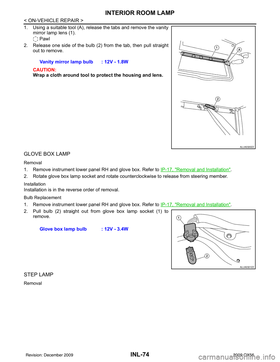
1. Using a suitable tool (A), release the tabs and remove the vanitymirror lamp lens (1).
Pawl
2. Release one side of the bulb (2) from the tab, then pull straight out to remove.
CAUTION:
Wrap a cloth around tool to protect the housing and lens.
GLOVE BOX LAMP
Removal
1. Remove instrument lower panel RH and glove box. Refer to IP-17, "Removal and Installation".
2. Rotate glove box lamp socket and rotate counterclockwise to release from steering member.
Installation
Installation is in the reverse order of removal.
Bulb Replacement
1. Remove instrument lower panel RH and glove box. Refer to IP-17, "Removal and Installation".
2. Pull bulb (2) straight out from glove box lamp socket (1) to remove.
STEP LAMP
Removal
Vanity mirror lamp bulb : 12V - 1.8W
ALLIA0320ZZ
Glove box lamp bulb : 12V - 3.4W
ALLIA0321ZZ
Revision: December 20092009 QX56
Page 2520 of 4171

INL-76
< ON-VEHICLE REPAIR >
INTERIOR ROOM LAMP
Installation is in the reverse order of removal.
Bulb Replacement
1. Using a suitable tool (A), release the pawls and remove personal lamp lens (1). Pawl
2. Pull bulb (2) straight out to remove.
CAUTION:
Wrap a cloth around tool to protect the housing and lens.
FOOTWELL LAMP
Removal
1. Rotate footwell lamp socket (3) counterclockwise to remove
from bracket.
Installation
Installation is in the reverse order of removal.
Bulb Replacement
1. Release the pawls and remove bulb shield (1) from bracket.
2. Pull bulb (2) straight out from footwell lamp socket (3) to remove. Personal lamp bulb : 12V - 6W
ALLIA0323ZZ
ALLIA0324ZZ
Footwell lamp bulb : 12V - 3.4W
Revision: December 20092009 QX56
Page 2522 of 4171

INL-78
< ON-VEHICLE REPAIR >
ILLUMINATION
1. Using a suitable tool, release the pawls and remove the cargolamp lens.
2. Release the cargo lamp bulb retainers (1), then pull bulb (2) straight out to remove.
CONSOLE ILLUMINATION LAMP (if equipped)
Removal
The console illumination lamp (1) is replaced as part of the front roof
console (2). Refer to INT-17, "
Removal and Installation".
: Vehicle front
: metal clip
Installation
Installation is in the reverse order of removal.
Bulb Replacement
1. Remove front roof console. Refer to INT-17, "Removal and Installation".
2. Rotate console illumination lamp bulb (1) counterclockwise, then pull straight out away from map lamp assembly (2) to remove.Cargo lamp bulb
: 12V - 8W
ALLIA0326ZZ
ALLIA0328ZZ
ALLIA0327ZZ
Revision: December 20092009 QX56
Page 2525 of 4171

INT-2
< SYMPTOM DIAGNOSIS >
SQUEAK AND RATTLE TROUBLE DIAGNOSES
SYMPTOM DIAGNOSIS
SQUEAK AND RATTLE TROUBLE DIAGNOSES
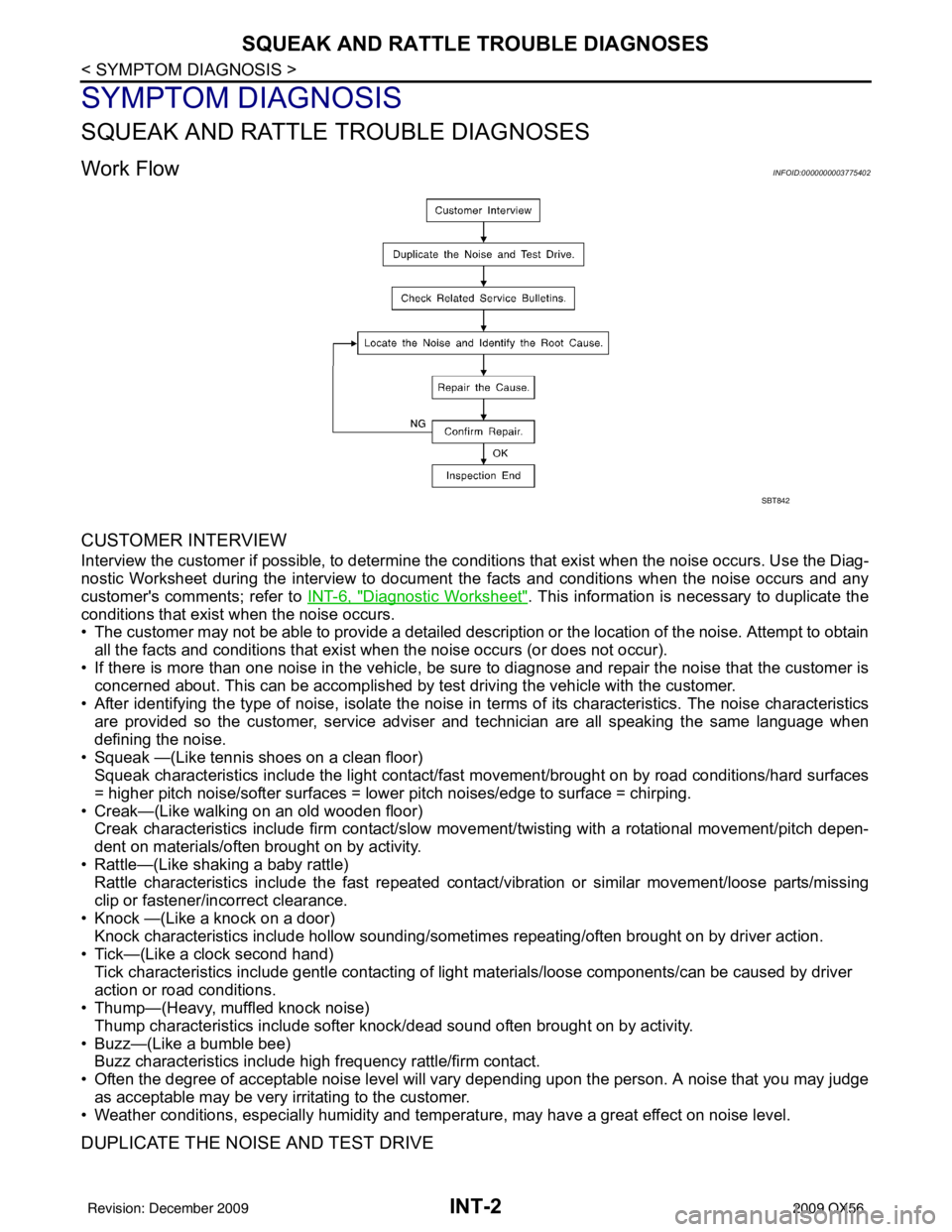
Work FlowINFOID:0000000003775402
CUSTOMER INTERVIEW
Interview the customer if possible, to determine the conditions that exist when the noise occurs. Use the Diag-
nostic Worksheet during the interview to document the facts and conditions when the noise occurs and any
customer's comments; refer to INT-6, "
Diagnostic Worksheet". This information is necessary to duplicate the
conditions that exist when the noise occurs.
• The customer may not be able to provide a detailed description or the location of the noise. Attempt to obtain
all the facts and conditions that exist w hen the noise occurs (or does not occur).
• If there is more than one noise in the vehicle, be sure to diagnose and repair the noise that the customer is
concerned about. This can be accomplished by test driving the vehicle with the customer.
• After identifying the type of noise, isolate the noise in terms of its characteristics. The noise characteristics
are provided so the customer, service adviser and technician are all speaking the same language when
defining the noise.
• Squeak —(Like tennis shoes on a clean floor) Squeak characteristics include the light contact/fast movement/brought on by road conditions/hard surfaces
= higher pitch noise/softer surfaces = lower pitch noises/edge to surface = chirping.
• Creak—(Like walking on an old wooden floor) Creak characteristics include firm contact/slow mo vement/twisting with a rotational movement/pitch depen-
dent on materials/often brought on by activity.
• Rattle—(Like shaking a baby rattle) Rattle characteristics include the fast repeated contac t/vibration or similar movement/loose parts/missing
clip or fastener/incorrect clearance.
• Knock —(Like a knock on a door) Knock characteristics include hollow sounding/someti mes repeating/often brought on by driver action.
• Tick—(Like a clock second hand) Tick characteristics include gentle contacting of light materials/loose components/can be caused by driver
action or road conditions.
• Thump—(Heavy, muffled knock noise)
Thump characteristics include softer k nock/dead sound often brought on by activity.
• Buzz—(Like a bumble bee) Buzz characteristics include hi gh frequency rattle/firm contact.
• Often the degree of acceptable noise level will vary depending upon the person. A noise that you may judge as acceptable may be very irritating to the customer.
• Weather conditions, especially humidity and temperat ure, may have a great effect on noise level.
DUPLICATE THE NOISE AND TEST DRIVE
SBT842
Revision: December 20092009 QX56
Page 2550 of 4171

IP-6
< SYMPTOM DIAGNOSIS >
SQUEAK AND RATTLE TROUBLE DIAGNOSES
SYMPTOM DIAGNOSIS
SQUEAK AND RATTLE TROUBLE DIAGNOSES
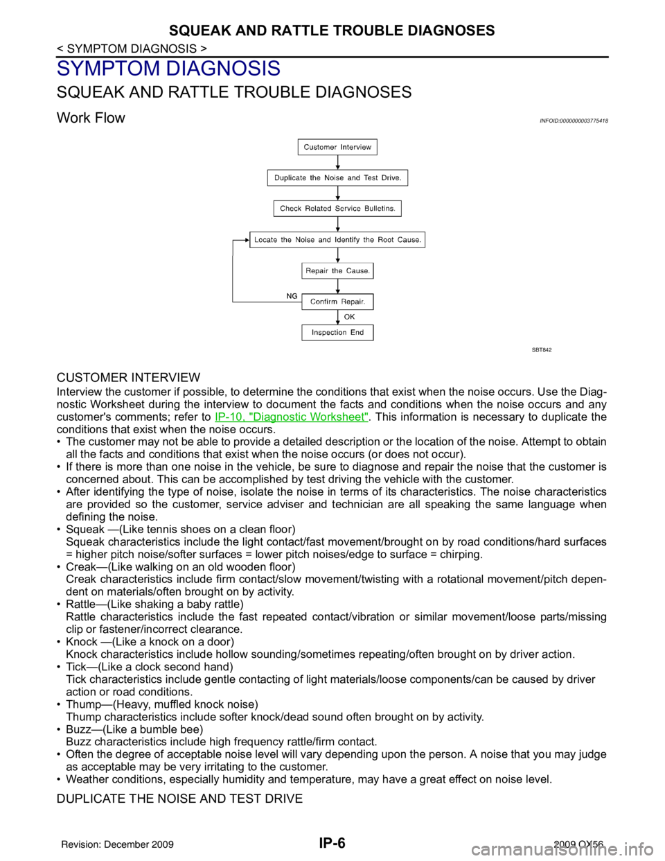
Work FlowINFOID:0000000003775418
CUSTOMER INTERVIEW
Interview the customer if possible, to determine the conditions that exist when the noise occurs. Use the Diag-
nostic Worksheet during the interview to document the facts and conditions when the noise occurs and any
customer's comments; refer to IP-10, "
Diagnostic Worksheet". This information is necessary to duplicate the
conditions that exist when the noise occurs.
• The customer may not be able to provide a detailed description or the location of the noise. Attempt to obtain
all the facts and conditions that exist w hen the noise occurs (or does not occur).
• If there is more than one noise in the vehicle, be sure to diagnose and repair the noise that the customer is
concerned about. This can be accomplished by test driving the vehicle with the customer.
• After identifying the type of noise, isolate the noise in terms of its characteristics. The noise characteristics
are provided so the customer, service adviser and technician are all speaking the same language when
defining the noise.
• Squeak —(Like tennis shoes on a clean floor) Squeak characteristics include the light contact/fast movement/brought on by road conditions/hard surfaces
= higher pitch noise/softer surfaces = lower pitch noises/edge to surface = chirping.
• Creak—(Like walking on an old wooden floor) Creak characteristics include firm contact/slow mo vement/twisting with a rotational movement/pitch depen-
dent on materials/often brought on by activity.
• Rattle—(Like shaking a baby rattle) Rattle characteristics include the fast repeated contac t/vibration or similar movement/loose parts/missing
clip or fastener/incorrect clearance.
• Knock —(Like a knock on a door) Knock characteristics include hollow sounding/someti mes repeating/often brought on by driver action.
• Tick—(Like a clock second hand) Tick characteristics include gentle contacting of light materials/loose components/can be caused by driver
action or road conditions.
• Thump—(Heavy, muffled knock noise)
Thump characteristics include softer k nock/dead sound often brought on by activity.
• Buzz—(Like a bumble bee) Buzz characteristics include hi gh frequency rattle/firm contact.
• Often the degree of acceptable noise level will vary depending upon the person. A noise that you may judge as acceptable may be very irritating to the customer.
• Weather conditions, especially humidity and temperat ure, may have a great effect on noise level.
DUPLICATE THE NOISE AND TEST DRIVE
SBT842
Revision: December 20092009 QX56
Page 2560 of 4171

IP-16
< ON-VEHICLE REPAIR >
CLUSTER LID C
CLUSTER LID C
Exploded ViewINFOID:0000000003775425
Removal and InstallationINFOID:0000000003775426
REMOVAL
1. Release the clips and remove cluster lid C lower.
2. Remove the upper and lower cluster lid C screws.
3. Release the clips, then pull cluster lid C rearward to removefrom instrument panel and pad assembly.
4. Disconnect electrical connectors.
INSTALLATION
Installation is in the reverse order of removal.
1. A/C and AV switch assembly 2. Cluster lid C 3. Center ventilator assembly LH
4. Audio switch LH 5. 4WD switch (if equipped)6. Cluster lid C lower/clock
7. Hazard switch 8. Audio switch RH9. Center ventilator assembly RH
Clip Pawl
AWJIA0237ZZ
ALJIA0078ZZ
Revision: December 20092009 QX56