clock INFINITI QX56 2009 Factory Workshop Manual
[x] Cancel search | Manufacturer: INFINITI, Model Year: 2009, Model line: QX56, Model: INFINITI QX56 2009Pages: 4171, PDF Size: 84.65 MB
Page 2102 of 4171

EXL-154
< REMOVAL AND INSTALLATION >
PUDDLE LAMP
PUDDLE LAMP
Removal and InstallationINFOID:0000000005864680
REMOVAL
1. Depress tab (1) on outer edge of puddle lamp housing.
2. Lower outer edge and slide puddle lamp housing out of door mirror.
3. Twist puddle lamp socket (1) counterclockwise to remove frompuddle lamp housing (2).
INSTALLATION
Installation is in the reverse order of removal.
Bulb ReplacementINFOID:0000000005864681
REMOVAL
1. Remove puddle lamp housing. Refer to EXL-154, "Removal and Installation".
2. Pull puddle lamp bulb (2) straight out from puddle lamp socket (1) to remove.
INSTALLATION
Installation is in the reverse order of removal.
LKIA0671E
LKIA0672E
LKIA0673E
Revision: December 20092009 QX56
Page 2103 of 4171

LICENSE PLATE LAMPEXL-155
< REMOVAL AND INSTALLATION >
C
DE
F
G H
I
J
K
M A
B
EXL
N
O P
LICENSE PLATE LAMP
Bulb ReplacementINFOID:0000000003776230
LICENSE PLATE LAMP
Removal
1. Remove back door lower finisher. Refer to EXT-24, "Removal and Installation".
2. Turn bulb socket counterclockwise to remove it.
3. Pull bulb from socket.
Installation
Installation is in the reverse order of removal.
Removal and InstallationINFOID:0000000003776231
LICENSE PLATE LAMP
Removal
1. Remove back door lower finisher. Refer to INT-21, "Removal and Installation".
2. Remove license plate lamp screws.
3. Remove license plate lamp.
Installation
Installation is in the reverse order of removal.
Revision: December 20092009 QX56
Page 2105 of 4171

REAR COMBINATION LAMPEXL-157
< REMOVAL AND INSTALLATION >
C
DE
F
G H
I
J
K
M A
B
EXL
N
O P
REAR COMBINATION LAMP
Bulb ReplacementINFOID:0000000003776234
REMOVAL
1. Remove rear combination lamp bolts.
2. Pull rear combination lamp to remove.
3. Turn bulb socket counterclockwise and unlock it.
4. Remove bulb.
INSTALLATION
Installation is in the reverse order of removal.
Removal and InstallationINFOID:0000000003776235
REMOVAL
1. Remove rear combination lamp bolts.
2. Pull rear combination lamp to remove.
3. Disconnect rear combination lamp connector.
INSTALLATION
Installation is in the reverse order of removal.
WKIA1393E
WKIA1393E
Revision: December 20092009 QX56
Page 2111 of 4171

SQUEAK AND RATTLE TROUBLE DIAGNOSESEXT-5
< SERVICE INFORMATION >
C
DE
F
G H
I
J
L
M A
B
EXT
N
O P
SQUEAK AND RATTLE TROUBLE DIAGNOSES
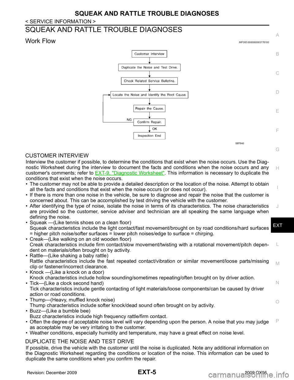
Work FlowINFOID:0000000003776100
CUSTOMER INTERVIEW
Interview the customer if possible, to determine the conditions that exist when the noise occurs. Use the Diag-
nostic Worksheet during the interv iew to document the facts and conditions when the noise occurs and any
customer's comments; refer to EXT-9, "
Diagnostic Worksheet". This information is necessary to duplicate the
conditions that exist when the noise occurs.
• The customer may not be able to provide a detailed descr iption or the location of the noise. Attempt to obtain
all the facts and conditions that exist when the noise occurs (or does not occur).
• If there is more than one noise in the vehicle, be sure to diagnose and repair the noise that the customer is
concerned about. This can be accomplished by test driving the vehicle with the customer.
• After identifying the type of noise, isolate the noise in terms of its characteristics. The noise characteristics
are provided so the customer, service adviser and technician are all speaking the same language when
defining the noise.
• Squeak —(Like tennis shoes on a clean floor)
Squeak characteristics include the light contact/fast movement/brought on by road conditions/hard surfaces
= higher pitch noise/softer surfaces = lower pitch noises/edge to surface = chirping.
• Creak—(Like walking on an old wooden floor)
Creak characteristics include firm contact/slow mo vement/twisting with a rotational movement/pitch depen-
dent on materials/often brought on by activity.
• Rattle—(Like shaking a baby rattle)
Rattle characteristics include the fast repeated contac t/vibration or similar movement/loose parts/missing
clip or fastener/incorrect clearance.
• Knock —(Like a knock on a door)
Knock characteristics include hollow sounding/someti mes repeating/often brought on by driver action.
• Tick—(Like a clock second hand) Tick characteristics include gentle contacting of li ght materials/loose components/can be caused by driver
action or road conditions.
• Thump—(Heavy, muffled knock noise) Thump characteristics include softer k nock/dead sound often brought on by activity.
• Buzz—(Like a bumble bee)
Buzz characteristics include high frequency rattle/firm contact.
• Often the degree of acceptable noise level will vary depending upon the person. A noise that you may judge as acceptable may be very irritating to the customer.
• Weather conditions, especially humidity and temperature, may have a great effect on noise level.
DUPLICATE THE NOISE AND TEST DRIVE
If possible, drive the vehicle with the customer until the noise is duplicated. Note any additional information on
the Diagnostic Worksheet regarding the conditions or lo cation of the noise. This information can be used to
duplicate the same conditions when you confirm the repair.
SBT842
Revision: December 20092009 QX56
Page 2161 of 4171

FL-8
< REMOVAL AND INSTALLATION >
FUEL LEVEL SENSOR UNIT, FUEL FILTER AND FUEL PUMP ASSEMBLY
9. Remove the inspection hole cover by turning the retainers 90 °
degrees clockwise.
• Remove the O-ring.
10. Disconnect the fuel level sensor, fuel filter, and fuel pump assembly electrical connector, the EVAP hose, and the fuel feed
hose.
Disconnect the quick connector as follows:
• Hold the sides of the connector, push in tabs and pull out the
tube.
• If the connector and the tube are stuck together, push and pull several times until they start to move. Then disconnect them
by pulling.
CAUTION:
LBIA0382E
LBIA0383E
SFE562A
Revision: December 20092009 QX56
Page 2166 of 4171

FUEL TANKFL-13
< REMOVAL AND INSTALLATION >
C
DE
F
G H
I
J
K L
M A
FL
NP
O
13. Remove the inspection hole cover by turning the retainers 90
°
degrees clockwise.
• Remove the O-ring.
14. Disconnect the fuel level sensor, fuel filter, and fuel pump assembly electrical connector, the EVAP hose, and the fuel feed
hose.
Disconnect the quick connector as follows:
• Hold the sides of the connector, push in tabs and pull out the
tube.
• If the connector and the tube are stuck together, push and pull several times until they start to move. Then disconnect them
by pulling.
CAUTION:
LBIA0382E
LBIA0383E
SFE562A
Revision: December 20092009 QX56
Page 2244 of 4171

GW-2
< SYMPTOM DIAGNOSIS >
SQUEAK AND RATTLE TROUBLE DIAGNOSIS
SYMPTOM DIAGNOSIS
SQUEAK AND RATTLE TROUBLE DIAGNOSIS
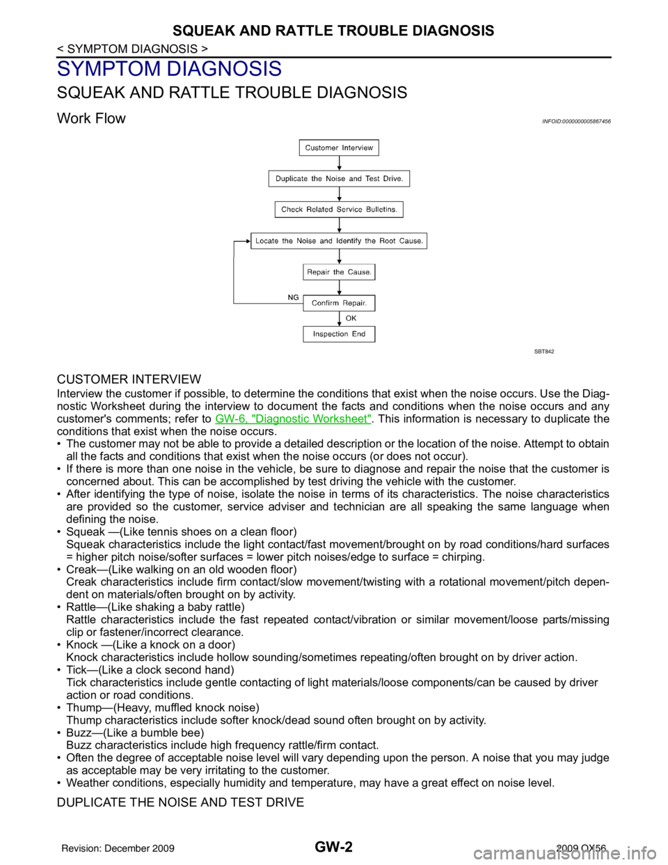
Work FlowINFOID:0000000005867456
CUSTOMER INTERVIEW
Interview the customer if possible, to determine the conditions that exist when the noise occurs. Use the Diag-
nostic Worksheet during the interview to document the facts and conditions when the noise occurs and any
customer's comments; refer to GW-6, "
Diagnostic Worksheet". This information is necessary to duplicate the
conditions that exist when the noise occurs.
• The customer may not be able to provide a detailed description or the location of the noise. Attempt to obtain
all the facts and conditions that exist w hen the noise occurs (or does not occur).
• If there is more than one noise in the vehicle, be sure to diagnose and repair the noise that the customer is
concerned about. This can be accomplished by test driving the vehicle with the customer.
• After identifying the type of noise, isolate the noise in terms of its characteristics. The noise characteristics
are provided so the customer, service adviser and technician are all speaking the same language when
defining the noise.
• Squeak —(Like tennis shoes on a clean floor) Squeak characteristics include the light contact/fast movement/brought on by road conditions/hard surfaces
= higher pitch noise/softer surfaces = lower pitch noises/edge to surface = chirping.
• Creak—(Like walking on an old wooden floor) Creak characteristics include firm contact/slow mo vement/twisting with a rotational movement/pitch depen-
dent on materials/often brought on by activity.
• Rattle—(Like shaking a baby rattle) Rattle characteristics include the fast repeated contac t/vibration or similar movement/loose parts/missing
clip or fastener/incorrect clearance.
• Knock —(Like a knock on a door) Knock characteristics include hollow sounding/someti mes repeating/often brought on by driver action.
• Tick—(Like a clock second hand) Tick characteristics include gentle contacting of light materials/loose components/can be caused by driver
action or road conditions.
• Thump—(Heavy, muffled knock noise)
Thump characteristics include softer k nock/dead sound often brought on by activity.
• Buzz—(Like a bumble bee) Buzz characteristics include hi gh frequency rattle/firm contact.
• Often the degree of acceptable noise level will vary depending upon the person. A noise that you may judge as acceptable may be very irritating to the customer.
• Weather conditions, especially humidity and temperat ure, may have a great effect on noise level.
DUPLICATE THE NOISE AND TEST DRIVE
SBT842
Revision: December 20092009 QX56
Page 2259 of 4171

FRONT DOOR GLASS AND REGULATORGW-17
< ON-VEHICLE REPAIR >
C
DE
F
G H
I
J
L
M A
B
GW
N
O P
• Removal and installation of the power window motor from the regulator.
• Installation of a new glass window.
• Installation of a new glass run.
Check the label on the power window motor for the part number. If the power window motor part number
matches one of the following, the limit switch must be reset using the “INSTALLATION WITHOUT RESET
SWITCH” procedure.
• 80730-ZT01A
• 80731-ZT01A
• 80730-ZM70B
• 80731-ZM70B
If the power window motor part number does not match one of the part numbers above, the limit switch must
be reset using the “INSTALLATION WITH RESET SWITCH” procedure.
NOTE:
Some of the power window motors with the part num bers above may appear to have a reset switch, but it will
not reset the limit switch.
INSTALLATION WITHOUT RESET SWITCH - (Motors listed above)
Check the label on the power window motor for the pa rt number. If the power window motor part number does
not match one of the above, use the “INSTALLATION WITH RESET SWITCH” procedure.
NOTE:
Some of the power window motors may appear to have a re set switch, but it will not reset the limit switch.
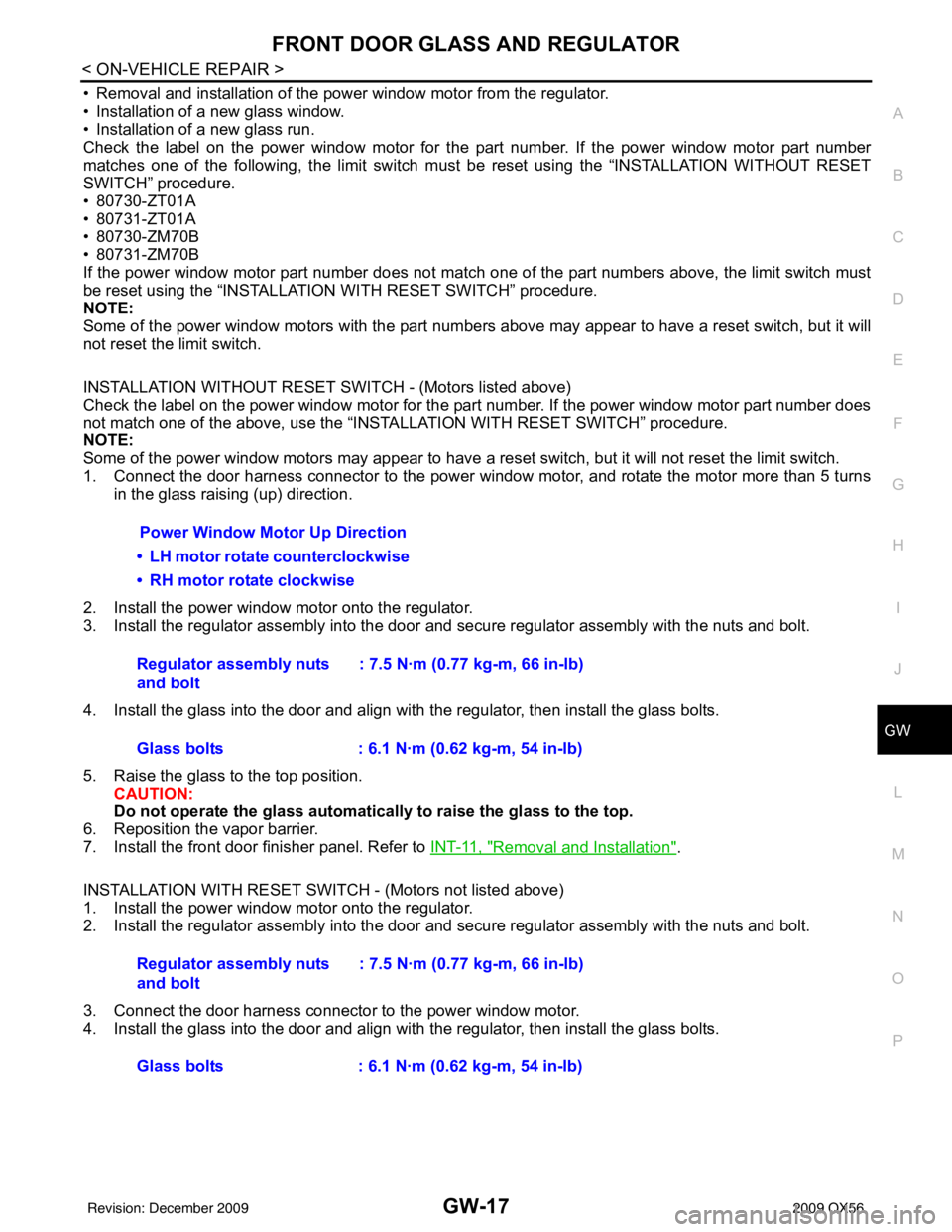
1. Connect the door harness connector to the power window motor, and rotate the motor more than 5 turns
in the glass raising (up) direction.
2. Install the power window motor onto the regulator.
3. Install the regulator assembly into the door and secure regulator assembly with the nuts and bolt.
4. Install the glass into the door and align with the regulator, then install the glass bolts.
5. Raise the glass to the top position. CAUTION:
Do not operate the glass automatical ly to raise the glass to the top.
6. Reposition the vapor barrier.
7. Install the front door finisher panel. Refer to INT-11, "
Removal and Installation".
INSTALLATION WITH RESET SWITCH - (Motors not listed above)
1. Install the power window motor onto the regulator.
2. Install the regulator assembly into the door and secure regulator assembly with the nuts and bolt.
3. Connect the door harness connector to the power window motor.
4. Install the glass into the door and align with the regulator, then install the glass bolts.
Power Window Motor Up Direction
• LH motor rotate counterclockwise
• RH motor rotate clockwise
Regulator assembly nuts
and bolt : 7.5 N·m (0.77 kg-m, 66 in-lb)
Glass bolts : 6.1 N·m (0.62 kg-m, 54 in-lb)
Regulator assembly nuts
and bolt : 7.5 N·m (0.77 kg-m, 66 in-lb)
Glass bolts : 6.1 N·m (0.62 kg-m, 54 in-lb)
Revision: December 20092009 QX56
Page 2276 of 4171

HA-12
< PRECAUTION >
PRECAUTIONS
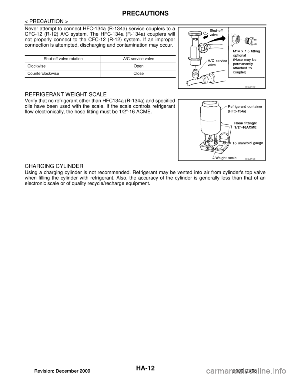
Never attempt to connect HFC-134a (R-134a) service couplers to a
CFC-12 (R-12) A/C system. The HFC-134a (R-134a) couplers will
not properly connect to the CFC-12 (R-12) system. If an improper
connection is attempted, discharging and contamination may occur.
REFRIGERANT WEIGHT SCALE
Verify that no refrigerant other than HFC134a (R-134a) and specified
oils have been used with the scale. If the scale controls refrigerant
flow electronically, the hose fitting must be 1/2”-16 ACME.
CHARGING CYLINDER
Using a charging cylinder is not recommended. Refrigerant may be vented into air from cylinder's top valve
when filling the cylinder with refrigerant. Also, the accu racy of the cylinder is generally less than that of an
electronic scale or of quality recycle/recharge equipment.
Shut-off valve rotati on A/C service valve
Clockwise Open
Counterclockwise Close
RHA273D
RHA274D
Revision: December 20092009 QX56
Page 2313 of 4171

SERVICE DATA AND SPECIFICATIONS (SDS)
HA-49
< SERVICE DATA AND SPECIFICATIONS (SDS)
C
D E
F
G H
J
K L
M A
B
HA
N
O P
SERVICE DATA AND SPECIFICATIONS (SDS)
SERVICE DATA AND SPECIFICATIONS (SDS)
Service Data and Specification (SDS)INFOID:0000000003775323
COMPRESSOR
OIL
REFRIGERANT
Make ZEXEL VALEO CLIMATE CONTROL
Model DKS-17D
Typ e Swash plate
Displacement 175.5 cm
3 (10.7 in3 ) / revolution
Cylinder bore × stroke 30.5 mm (1.20 in) x 24.0 mm (0.94 in)
Direction of rotation Clockwise (viewed from drive end)
Drive belt Poly V
Name NISSAN A/C System Oil Type S
Capacity 290 m (9.8 US fl oz, 10.2 Imp fl oz)
Typ eHFC 134a (R-134a)
Capacity 1.08 ± 0.05 kg (2.38 ± 0.11 lb)
Revision: December 20092009 QX56