clock INFINITI QX56 2009 Factory Owner's Guide
[x] Cancel search | Manufacturer: INFINITI, Model Year: 2009, Model line: QX56, Model: INFINITI QX56 2009Pages: 4171, PDF Size: 84.65 MB
Page 1877 of 4171

EM-54
< ON-VEHICLE REPAIR >
CAMSHAFT
5. Obtain compression TDC of No. 1 cylinder as follows:
a. Turn the crankshaft pulley clockwise to align the TDC identifica-tion notch (without paint mark) with the timing indicator on the
front cover.
b. At this time, make sure both intake and exhaust cam lobes of No. 1 cylinder (top front on LH bank) point outside.
• If they do not point outside, turn crankshaft pulley once more.
6. Disconnect and remove the camshaft position sensor. Refer to EM-44, "
Exploded View".
7. Disconnect and remove the intake valve timing c ontrol position sensor (RH and LH). Refer to EM-44,
"Exploded View".
8. Disconnect and remove the intake valve timing control solenoid valve (RH and LH). Refer to EM-44,
"Exploded View".
9. Remove the intake valve timing control solenoid cover RH bank (A) and intake valve timing control solenoid cover LH bank (B)
as follows:
a. Loosen and remove the bolts in reverse order as shown.
b. Cut the liquid gasket and remove the covers using Tool.
CAUTION:
Do not damage mating surfaces.
10. Paint alignment marks on the RH bank (A) timing chain links (C) and LH bank (B) timing chain links (D) and align with the cam-
shaft sprocket alignment marks (E) and (F).
11. Remove the chain tensioner (LH) using the following steps. WARNING:
Plunger, spring, and spring seat pop out when squeezing return-proof clip without holding
plunger head. It may cause serious injuries. Always hold plunger head when removing.
KBIA2476E
KBIA0400J
Tool number : KV10111100 (J-37228)
AWBIA0815ZZ
AWBIA0154ZZ
Revision: December 20092009 QX56
Page 1892 of 4171

CYLINDER HEADEM-69
< ON-VEHICLE REPAIR >
C
DE
F
G H
I
J
K L
M A
EM
NP
O
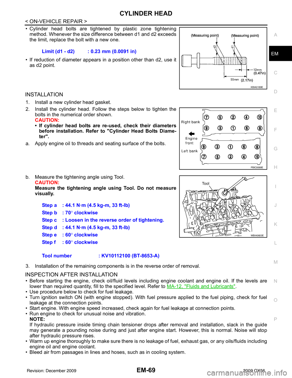
• Cylinder head bolts are tightened by plastic zone tightening
method. Whenever the size difference between d1 and d2 exceeds
the limit, replace the bolt with a new one.
• If reduction of diameter appears in a position other than d2, use it as d2 point.
INSTALLATION
1. Install a new cylinder head gasket.
2. Install the cylinder head. Follow the steps below to tighten the bolts in the numerical order shown.
CAUTION:
• If cylinder head bolts are re-used, check their diameters
before installation. Refer to "Cylinder Head Bolts Diame-
ter".
a. Apply engine oil to threads and seating surface of the bolts.
b. Measure the tightening angle using Tool. CAUTION:
Measure the tightening angl e using Tool. Do not measure
visually.
3. Installation of the remaining components is in the reverse order of removal.
INSPECTION AFTER INSTALLATION
• Before starting the engine, check oil/fluid levels including engine coolant and engine oil. If the levels are lower than required quantity, fill to the specified level. Refer to MA-12, "
Fluids and Lubricants".
• Use procedure below to check for fuel leakage.
• Turn ignition switch ON (with engine stopped). With fuel pressure applied to the fuel piping, check for fuel
leakage at the connection points.
• Start engine. With engine speed increased, check again for fuel leakage at connection points.
• Run engine to check for unusual noise and vibration.
NOTE:
If hydraulic pressure inside timing chain tensioner drops after removal and installation, slack in the guide
may generate a pounding noise during and just after engine start. However, this is normal. Noise will stop
after hydraulic pressure rises.
• Warm up engine thoroughly to make sure there is no leakage of fuel, exhaust gas, or any oils/fluids including
engine oil and engine coolant.
• Bleed air from passages in lines and hoses, such as in cooling system. Limit (d1 - d2) : 0.23 mm (0.0091 in)
KBIA0189E
PBIC0068E
Step a : 44.1 N·m (4.5 kg-m, 33 ft-lb)
Step b : 70°
clockwise
Step c : Loosen in the reverse order of tightening.
Step d : 44.1 N·m (4.5 kg-m, 33 ft-lb)
Step e : 60 ° clockwise
Step f : 60° clockwise
Tool number : KV10112100 (BT-8653-A)
WBIA0603E
Revision: December 20092009 QX56
Page 1912 of 4171

ENGINE UNITEM-89
< DISASSEMBLY AND ASSEMBLY >
C
DE
F
G H
I
J
K L
M A
EM
NP
O
12. Install the connecting rod bearings to the connecting rod and
connecting rod cap.
• When installing the connecting rod bearings, apply engine oilto the bearing surface (inside). Do not apply oil to the back
surface, but thoroughly clean it.
• When installing, align the connecting rod bearing stopper pro-
trusion with the cutout of the connecting rod to install.
• Check that the oil holes on the connecting rod and those on the corresponding bearing are aligned.
13. Install the piston and connecting rod assembly to the crankshaft using Tool.
• Position the crankshaft pin corresponding to the connecting
rod to be installed onto bottom dead center.
• Apply engine oil sufficiently to the cylinder bore, piston, and
crankshaft pin.
• Match the cylinder position with the cylinder No. on the con- necting rod to install.
• Install the piston with the front mark on the piston crown facing the front of the engine.
CAUTION:
Be careful not to damage the crankshaft pin, resu lting from an interference of the connecting rod
big end.
14. Install connecting rod cap. • Match the stamped cylinder number marks on the connectingrod with those on the cylinder cap to install.
15. Tighten connecting rod bolts using Tool. • Apply engine oil to threads and seats of connecting rod bolts.
• After tightening bolts, make sure the crankshaft rotatessmoothly.
• Check connecting rod side clearance. Refer to EM-90,
"Inspection After Disassembly".
PBIC0266E
Tool number : EM03470000 (J-8037)
WBIA0626E
KBIA2536E
Tool number : KV10112100 (BT-8653-A)
Connecting rod bolts
Step 1 : 19.6 N·m (1.5 kg-m, 11 ft-lb)
Step 2: 90° clockwise
WBIA0627E
Revision: December 20092009 QX56
Page 2058 of 4171

EXL-110
< ECU DIAGNOSIS >
BCM (BODY CONTROL MODULE)
19 V/WRemote keyless entry
receiver (power sup-
ply) Output OFF Ignition switch OFF
20 G/W Remote keyless entry
receiver (signal) Input OFFStand-by (keyfob buttons re-
leased)
When remote keyless entry
receiver receives signal from
keyfob (keyfob buttons
pressed)
21 G NATS antenna amp. Input OFF
→
ON Ignition switch (OFF
→ ON)Just after turning ignition switch
ON: Pointer of tester should
move for approx. 1 second, then return to battery voltage.
22 W/V BUS — —Ignition switch ON or power
window timer operates
23 G/O Security indicator
lamp Output OFF
Goes OFF
→ illuminates (Ev-
ery 2.4 seconds) Battery voltage
→ 0V
25 BR NATS antenna amp. Input OFF
→
ON Ignition switch (OFF
→ ON)Just after turning ignition switch
ON: Pointer of tester should
move for approx. 1 second, then return to battery voltage.
26 Y/L Rear wiper auto stop
switch 2 Input ONRise up position (rear wiper
arm on stopper)
0V
A Position (full clockwise stop
position) 0V
Forward sweep (counterclock-
wise direction) Fluctuating
B Position (full counterclock-
wise stop position) Battery voltage
Reverse sweep (clockwise di-
rection) Fluctuating
27 W/R Compressor ON sig-
nal Input ONA/C switch OFF
5V
A/C switch ON 0V
Te r m i n a l
Wire
color Signal name Signal
input/
output Measuring condition
Reference value or waveform
(Approx.)
Ignition
switch Operation or condition
LIIA1893E
LIIA1894E
LIIA1895E
PIIA2344E
Revision: December 20092009 QX56
Page 2060 of 4171

EXL-112
< ECU DIAGNOSIS >
BCM (BODY CONTROL MODULE)
44 ORear wiper auto stop
switch 1 Input ONRise up position (rear wiper
arm on stopper)
0V
A Position (full clockwise stop
position) Battery voltage
Forward sweep (counterclock-
wise direction) Fluctuating
B Position (full counterclock-
wise stop position) 0V
Reverse sweep (clockwise di-
rection) Fluctuating
47 SB Front door switch LH Input OFF ON (open)
0V
OFF (closed) Battery voltage
48 R/Y Rear door switch LH Input OFF ON (open)
0V
OFF (closed) Battery voltage
49 R Cargo lamp Output OFFAny door open (ON)
0V
All doors closed (OFF) Battery voltage
51 G/Y Trailer turn signal
(right) Output ON Turn right ON
52 G/B Trailer turn signal (l eft) Output ON Turn left ON
53 L/W Glass hatch lock actu-
ator
Output OFFGlass hatch switch released
0
Glass hatch switch pressed Battery
54 Y Rear wiper output cir-
cuit 2 Input ONRise up position (rear wiper
arm on stopper)
0V
A Position (full clockwise stop
position) 0V
Forward sweep (counterclock-
wise direction) 0V
B Position (full counterclock-
wise stop position) Battery voltage
Reverse sweep (clockwise di-
rection) Battery voltage
55 SB Rear wiper output cir-
cuit 1 Output ONOFF
0
ON Battery voltage
56 R/G Battery saver output Output OFF
30 minutes after ignition
switch is turned OFF 0V
ON — Battery voltage
57 Y/R Battery power supply Input OFF —Battery voltage
Te r m i n a l
Wire
color Signal name Signal
input/
output Measuring condition
Reference value or waveform
(Approx.)
Ignition
switch Operation or condition
SKIA3009J
SKIA3009J
Revision: December 20092009 QX56
Page 2093 of 4171

ADJUSTMENT AND INSPECTIONEXL-145
< ON-VEHICLE REPAIR >
C
DE
F
G H
I
J
K
M A
B
EXL
N
O P
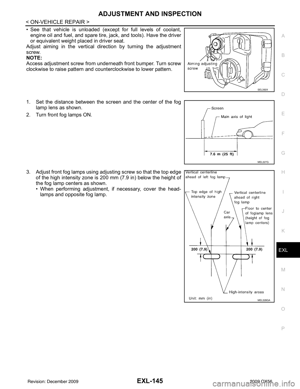
• See that vehicle is unloaded (except for full levels of coolant, engine oil and fuel, and spare tire, jack, and tools). Have the driver
or equivalent weight placed in driver seat.
Adjust aiming in the vertical direction by turning the adjustment
screw.
NOTE:
Access adjustment screw from underneath front bumper. Turn screw
clockwise to raise pattern and c ounterclockwise to lower pattern.
1. Set the distance between the screen and the center of the fog lamp lens as shown.
2. Turn front fog lamps ON.
3. Adjust front fog lamps using adjusting screw so that the top edge of the high intensity zone is 200 mm (7.9 in) below the height of
the fog lamp centers as shown.
• When performing adjustment, if necessary, cover the head-lamps and opposite fog lamp.
SEL350X
MEL327G
MEL328GA
Revision: December 20092009 QX56
Page 2094 of 4171

EXL-146
< REMOVAL AND INSTALLATION >
HEADLAMP
REMOVAL AND INSTALLATION
HEADLAMP
Bulb ReplacementINFOID:0000000003776222
CAUTION:
• Disconnect battery negative terminal before touching xenon bulb or headlamp wiring harness
assembly.
• Turn headlamp switch OFF before disconnecting headlamp harness connector.
• Do not touch bulb by hand right after being turned off. Burning may result.
• Do not touch the glass of bulb directly by hand. Keep grease and other oily substances away from it.
• Do not turn xenon bulb ON wh en xenon bulb is removed from front combination lamp assembly.
• After installing the bulb, be sure to install the bulb socket securely to ensure watertightness.
• Do not leave bulb out of front combination lamp assembly for a long time because dust, moisture,
smoke, etc. may affect the performa nce of the lamp. When replacing bulb, be sure to replace it with a
new one.
HEADLAMP (OUTER SIDE), FOR LOW BEAM
Removal
1. Position fender protector aside.
2. Turn headlamp switch OFF.
3. Disconnect battery negative terminal.
4. Remove ballast.
5. Disconnect headlamp electrical connector.
6. Release bulb retaining spring and pull bulb straight out.
Installation
Installation is in the reverse order of removal.
HEADLAMP (INNER SIDE), FOR HIGH BEAM
Removal
1. Turn headlamp switch OFF.
2. Disconnect headlamp electrical connector.
3. Turn the bulb counterclockwise to remove it.
Installation
Installation is in the reverse order of removal.
FRONT PARKING LAMP (INNER OR OUTER)
Removal
1. Turn the bulb socket counterclockwise to unlock it.
2. Pull the bulb to remove it from the socket.
Installation
Installation is in the reverse order of removal.
SIDE MARKER LAMP (FRONT)
Removal
1. Position fender protector aside.
2. Turn the side marker lamp (front) bulb socket counterclockwise and remove side marker lamp (front) bulb socket.
3. Pull to remove side marker lamp (front) fr om the side marker lamp (front) bulb socket.
Installation
Installation is in the reverse order of removal.
Revision: December 20092009 QX56
Page 2096 of 4171

EXL-148
< REMOVAL AND INSTALLATION >
HEADLAMP
Disassembly
1. Remove ballast.
2. Release xenon bulb retaining spring and remove xenon bulb.
3. Turn high beam bulb counterclockwise to unlock and remove high beam bulb.
4. Turn parking lamp bulb socket counterclockwise to unlock and remove parking lamp bulb.
5. Turn side marker lamp (front) bulb socket counterclockwise to unlock and remove side marker lamp (front)
bulb.
Assembly
Assembly is in the reverse order of disassembly.
4. Xenon bulb (low beam) 5. Side marker lamp (front) bulb 6. Ballast
7. Wiring harness assembly
Revision: December 20092009 QX56
Page 2097 of 4171

AUTO LIGHT SYSTEMEXL-149
< REMOVAL AND INSTALLATION >
C
DE
F
G H
I
J
K
M A
B
EXL
N
O P
AUTO LIGHT SYSTEM
Removal and InstallationINFOID:0000000003776225
OPTICAL SENSOR
Removal
1. Remove defroster grille. Refer to IP-12, "Exploded View".
2. Disconnect the optical sensor connector.
3. Turn the optical sensor counterclockwise to remove it from defroster grille.
Installation
Installation is in the reverse order of removal.
WKIA1061E
Revision: December 20092009 QX56
Page 2098 of 4171

EXL-150
< REMOVAL AND INSTALLATION >
FRONT FOG LAMP
FRONT FOG LAMP
Bulb ReplacementINFOID:0000000003776226
FRONT FOG LAMP
Removal
1. Remove the front turn/fog lamp assembly. Refer to EXL-150, "Removal and Installation".
2. Turn the bulb cover counterclockwise to remove it.
3. Unlatch retaining spring.
4. Remove bulb and disconnect the connector. CAUTION:
• Do not touch the glass of bulb directly by hand. Keep
grease and other oily substances away from it. Do not
touch bulb by hand while it is lit or right after being turned
off. Burning may result.
• Do not leave bulb out of fog la mp reflector for a long time
because dust, moisture smoke, etc. may affect the perfor-
mance of fog lamp. When replacing bulb, be sure to
replace it with new one.
Installation
Installation is in the reverse order of removal.
Removal and InstallationINFOID:0000000003776227
FRONT FOG LAMP
The fog lamp is a semi-sealed beam type which uses a replaceable halogen bulb.
CAUTION:
• Do not leave fog lamp assembly without bulb for a long period of time. Dust, moisture, smoke, etc. entering the fog lamp body may affect the perf ormance. Remove the bulb from the headlamp assem-
bly just before replacement bulb is installed.
• Grasp only the plastic base when handling the bulb. Never touch the glass envelope. Touching the
glass could significantly affect the bulb life and/or fog lamp performance.
Removal
1. Remove the front turn/fog lamp finisher.
2. Remove bolt and pull fog lamp out of front fascia.
3. Disconnect electrical connector.
WKIA1886E
WKIA1887E
WKIA1888E
Revision: December 20092009 QX56