brake fluid INFINITI QX56 2009 Factory Manual PDF
[x] Cancel search | Manufacturer: INFINITI, Model Year: 2009, Model line: QX56, Model: INFINITI QX56 2009Pages: 4171, PDF Size: 84.65 MB
Page 2703 of 4171

MA-30
< ON-VEHICLE MAINTENANCE >
CHASSIS AND BODY MAINTENANCE
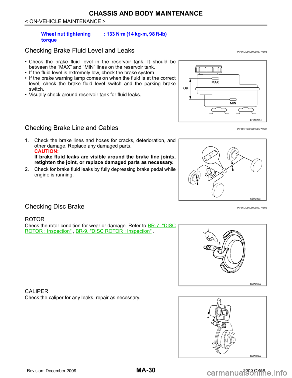
Checking Brake Fluid Level and Leaks
INFOID:0000000003777006
• Check the brake fluid level in the reservoir tank. It should be between the “MAX” and “MIN” lines on the reservoir tank.
• If the fluid level is extremely low, check the brake system.
• If the brake warning lamp comes on when the fluid is at the correct level, check the brake fluid level switch and the parking brake
switch.
• Visually check around reservoir tank for fluid leaks.
Checking Brake Line and CablesINFOID:0000000003777007
1. Check the brake lines and hoses for cracks, deterioration, and other damage. Replace any damaged parts.
CAUTION:
If brake fluid leaks are visible around the brake line joints,
retighten the joint, or replace damaged parts as necessary.
2. Check for brake fluid leaks by fully depressing brake pedal while engine is running.
Checking Disc BrakeINFOID:0000000003777008
ROTOR
Check the rotor condition for wear or damage. Refer to BR-7, "DISC
ROTOR : Inspection" , BR-9, "DISC ROTOR : Inspection" .
CALIPER
Check the caliper for any l eaks, repair as necessary.
Wheel nut tightening
torque
: 133 N·m (14 kg-m, 98 ft-lb)
LFIA0225E
SBR389C
SMA260A
SMA922A
Revision: December 20092009 QX56
Page 2704 of 4171

CHASSIS AND BODY MAINTENANCEMA-31
< ON-VEHICLE MAINTENANCE >
C
DE
F
G H
I
J
K L
M B
MA
N
O A
PA D
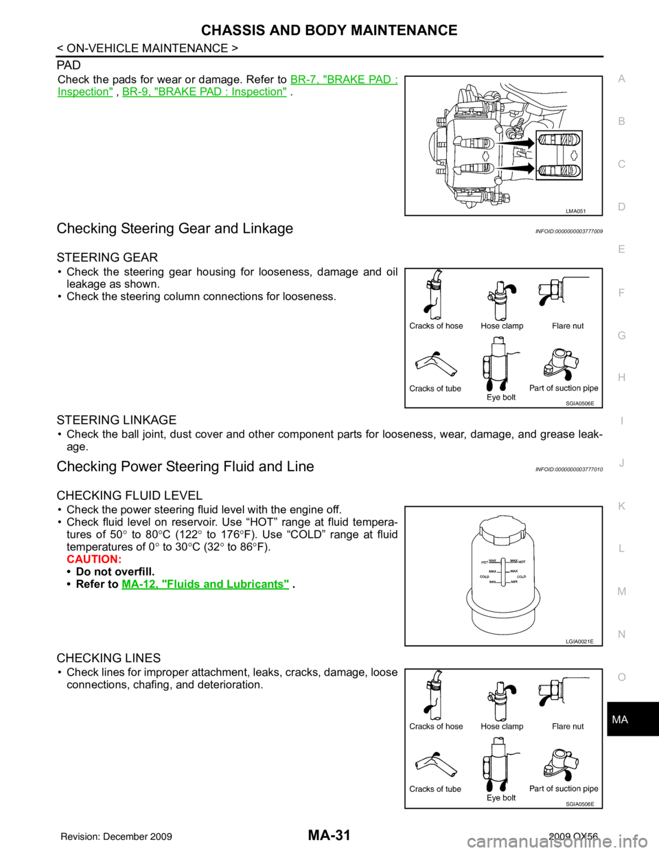
Check the pads for wear or damage. Refer to
BR-7, "BRAKE PAD :
Inspection" , BR-9, "BRAKE PAD : Inspection" .
Checking Steering Ge ar and LinkageINFOID:0000000003777009
STEERING GEAR
• Check the steering gear housing for looseness, damage and oil
leakage as shown.
• Check the steering column connections for looseness.
STEERING LINKAGE
• Check the ball joint, dust cover and other component parts for looseness, wear, damage, and grease leak-
age.
Checking Power Steering Fluid and LineINFOID:0000000003777010
CHECKING FLUID LEVEL
• Check the power steering fluid level with the engine off.
• Check fluid level on reservoir. Use “HOT” range at fluid tempera- tures of 50 ° to 80° C (122° to 176° F). Use “COLD” range at fluid
temperatures of 0 ° to 30° C (32° to 86° F).
CAUTION:
• Do not overfill.
• Refer to MA-12, "
Fluids and Lubricants" .
CHECKING LINES
• Check lines for improper attachment, leaks, cracks, damage, loose
connections, chafing, and deterioration.
LMA051
SGIA0506E
LGIA0021E
SGIA0506E
Revision: December 20092009 QX56
Page 2730 of 4171

MWI-8
< FUNCTION DIAGNOSIS >
METER SYSTEM
SPEEDOMETER
SPEEDOMETER : System DiagramINFOID:0000000003776585
SPEEDOMETER : System DescriptionINFOID:0000000003776586
The ABS actuator and electric unit (control unit) provides a vehicle speed signal to the combination meter via
CAN communication lines.
ABS actuator and electric unit
(control unit) Transmits the vehicle speed signal to the combination meter with CAN communication line.
BCM • Transmits signals provided by various units to the combination meter with CAN communication
line.
• Transmits the security signal to the combination meter.
TCM • Transmits shift position signal to the combination meter with CAN communication line.
• Transmits A/T oil temperature signal to the combination meter with CAN communication line.
Washer level switch Transmits the washer level signal to the combination meter.
Brake fluid level switch Transmits the brake fluid level switch signal to the combination meter.
Parking brake switch Refer to MWI-36, "
Description".
Unit
Description
WKIA5370E
Revision: December 20092009 QX56
Page 2742 of 4171

MWI-20
< FUNCTION DIAGNOSIS >
METER SYSTEM
INFORMATION DISPLAY : System Diagram
INFOID:0000000003776621
INFORMATION DISPLAY : System DescriptionINFOID:0000000003776622
FUNCTION
The information display can indicate the following items.
• Intelligent Key operation information
• Maintenance information
• Warning/Indication messages (Door/liftgate/liftgate glass open, low fuel, low washer fluid, parking brake, A/T
oil temp)
DOOR OPEN WARNING
This warning appears when the ignition switch is ON and the front door LH, front door RH, rear door LH, rear
door RH, back door or glass hatch is opened. The BCM receives a door switch signal from the front door
switch LH, front door switch RH, rear door switch LH, rear door switch RH, back door latch and glass hatch
ajar switch. The BCM sends the door switch signal to the combination meter via CAN communication lines.
Then, when the ignition switch is turned ON, the warning message is displayed.
LOW FUEL WARNING
This warning appears when the fuel level in the fuel tank is less than approximately 11.4 (3 US gal, 2.5 Imp
gal). A variable resistor signal is supplied to the combination meter from the fuel level sensor unit to determine
the amount of fuel in the fuel tank.
LOW WINDSHIELD WASHER FLUID WARNING
This warning appears when the windshield washer fluid level is low. When the windshield washer fluid level is
low, the washer level switch provides a ground signal to the combination meter (unified meter control unit).
Once fluid is added, the message will stay on for 30 seconds and then turn off.
PARKING BRAKE INDICATOR
When the parking brake is applied, the parking brake switch provides a ground signal to the combination
meter (unified meter control unit). Then, when the igni tion switch is turned ON and vehicle speed is greater
than 7 km/h (4 MPH), the message is displayed.
Refer to Owner’s Manual for additional information display items.
AWNIA0202GB
Revision: December 20092009 QX56
Page 2749 of 4171

MWI
DIAGNOSIS SYSTEM (METER)MWI-27
< FUNCTION DIAGNOSIS >
C
DE
F
G H
I
J
K L
M B A
O P
NOTE:
Some items are not available due to vehicle specification.
*: The monitor will indicate “OFF” even though the brake warnin g lamp is on if either of the following conditions exist.
• The parking brake is engaged
• The brake fluid level is low CRUISE W/L [ON/OFF]
X Indicates [ON/OFF] condition of CRUISE warning lamp.
4WD LOCK SW [ON/OFF] X Indicates [ON/OFF] condition of 4WD lock switch.
4WD LOCK IND [ON/OFF] X Indicates [ON/OFF] condition of 4WD lock indicator.
SEAT BELT W/L [ON/OFF] X Indicates [ON/OFF] condition of seat belt warning lamp.
FR FOG IND [ON/OFF] X This item is not used for this model. “OFF” is always displayed.
RR FOG IND [ON/OFF] X This item is not used for this model. “OFF” is always displayed.
LIGHT IND [ON/OFF] X Indicates [ON/OFF] condition of light indicator.
PNP P SW [ON/OFF] XX Indicates [ON/OFF] condition of park/neutral position P switch.
PNP N SW [ON/OFF] XX Indicates [ON/OFF] condition of park/neutral position N switch.
4WD W/L [ON/OFF] X Indicates [ON/OFF] condition of 4WD warning lamp.
Display item [Unit]
MAIN
SIGNALS SELECTION
FROM MENU Description
Revision: December 20092009 QX56
Page 2764 of 4171

MWI-42
< ECU DIAGNOSIS >
COMBINATION METER
ECU DIAGNOSIS
COMBINATION METER
Reference ValueINFOID:0000000003776653
TERMINAL LAYOUT
PHYSICAL VALUES
WKIA5724E
Te r m i -nal Wire
color Item Condition
Reference value (V)
(Approx.)
Ignition
switch Operation or condition
3 Y/L Fuel level sensor signal — —Refer to MWI-12, "
FUEL GAUGE : System
Description".
4 B/P Fuel level sensor ground ON —0
6 BR/W Generator ONGenerator voltage low
0
Generator voltage normal Battery voltage
10 L CAN-H —— —
11 P C A N - L —— —
13 P Air bag warning lamp in-
put ONAir bag warning lamp ON
4
Air bag warning lamp OFF 0
15 BR CK SUSP warning lamp
input —CK SUSP warning lamp
ON
0
CK SUSP warning lamp
OFF Battery voltage
20 B Ground —— 0
21 O/L Ignition switch ON or
START ON
— Battery voltage
23 W/L Washer fluid level switch ON Washer fluid level low
0
Washer fluid level normal Battery voltage
24 O/B Seat belt buckle switch
LH ONUnfastened (ON)
0
Fastened (OFF) Battery voltage
25 P/L Seat belt buckle switch
RH ONUnfastened (ON)
0
Fastened (OFF) Battery voltage
31 G Parking brake switch ON Parking brake applied
0
Parking brake released Battery voltage
32 P/B Brake fluid level switch ON Brake fluid level low
0
Brake fluid level normal Battery voltage
33 R/G Stop lamp switch —Brake pedal depressed
Battery voltage
Brake pedal released 0
Revision: December 20092009 QX56
Page 2918 of 4171

PG
HARNESSPG-47
< COMPONENT DIAGNOSIS >
C
DE
F
G H
I
J
K L
B A
O P
N
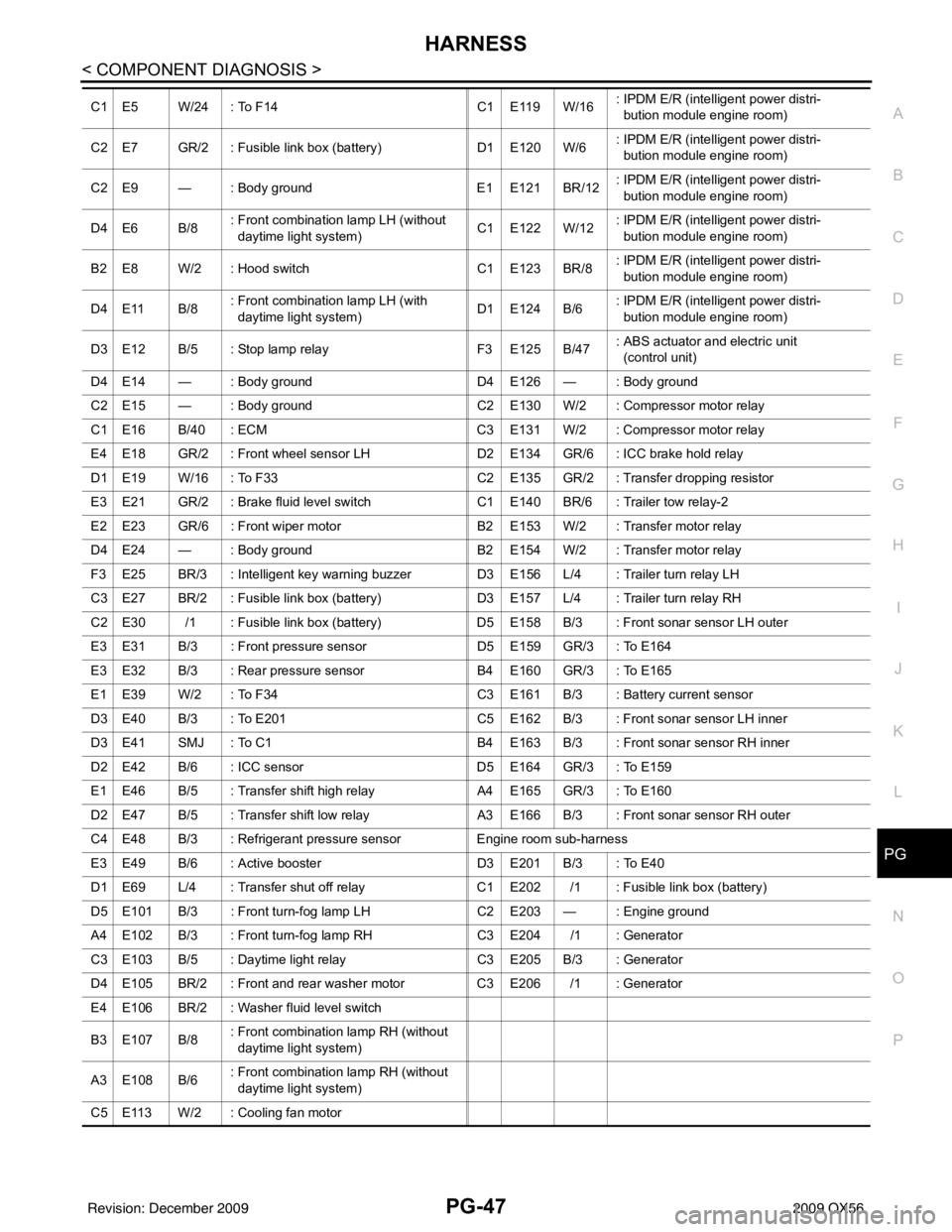
C1 E5 W/24 : To F14
C1 E119 W/16: IPDM E/R (intelligent power distri-
bution module engine room)
C2 E7 GR/2 : Fusible link box (battery) D1 E120 W/6: IPDM E/R (intelligent power distri-
bution module engine room)
C2 E9 — : Body ground E1 E121 BR/12: IPDM E/R (intelligent power distri-
bution module engine room)
D4 E6 B/8 : Front combination lamp LH (without
daytime light system) C1 E122 W/12: IPDM E/R (intelligent power distri-
bution module engine room)
B2 E8 W/2 : Hood switch C1 E123 BR/8: IPDM E/R (intelligent power distri-
bution module engine room)
D4 E11 B/8 : Front combination lamp LH (with
daytime light system) D1 E124 B/6
: IPDM E/R (intelligent power distri-
bution module engine room)
D3 E12 B/5 : Stop lamp relay F3 E125 B/47: ABS actuator and electric unit
(control unit)
D4 E14 — : Body ground D4 E126 — : Body ground
C2 E15 — : Body ground C2 E130 W/2 : Compressor motor relay
C1 E16 B/40 : ECM C3 E131 W/2 : Compressor motor relay
E4 E18 GR/2 : Front wheel sensor LH D2 E134 GR/6 : ICC brake hold relay
D1 E19 W/16 : To F33 C2 E135 GR/2 : Transfer dropping resistor
E3 E21 GR/2 : Brake fluid level swit chC1 E140 BR/6 : Trailer tow relay-2
E2 E23 GR/6 : Front wiper motor B2 E153 W/2 : Transfer motor relay
D4 E24 — : Body ground B2 E154 W/2 : Transfer motor relay
F3 E25 BR/3 : Intelligent key warning buzzer D3 E156 L/4 : Trailer turn relay LH
C3 E27 BR/2 : Fusible link box (battery) D3 E157 L/4 : Trailer turn relay RH
C2 E30 /1 : Fusible link box (battery) D5 E158 B/3 : Front sonar sensor LH outer
E3 E31 B/3 : Front pressure sensor D5 E159 GR/3 : To E164
E3 E32 B/3 : Rear pressure sensor B4 E160 GR/3 : To E165
E1 E39 W/2 : To F34 C3 E161 B/3 : Battery current sensor
D3 E40 B/3 : To E201 C5 E162 B/3 : Front sonar sensor LH inner
D3 E41 SMJ : To C1 B4 E163 B/3 : Front sonar sensor RH inner
D2 E42 B/6 : ICC sensor D5 E164 GR/3 : To E159
E1 E46 B/5 : Transfer shift high relay A4 E165 GR/3 : To E160
D2 E47 B/5 : Transfer shift low relay A3 E166 B/3 : Front sonar sensor RH outer
C4 E48 B/3 : Refrigerant pressure sensor Engine room sub-harness
E3 E49 B/6 : Active booster D3 E201 B/3 : To E40
D1 E69 L/4 : Transfer shut off relay C1 E202 /1 : Fusible link box (battery)
D5 E101 B/3 : Front turn-fog lamp LH C2 E203 — : Engine ground
A4 E102 B/3 : Front turn-fog lamp RH C3 E204 /1 : Generator
C3 E103 B/5 : Daytime light relay C3 E205 B/3 : Generator
D4 E105 BR/2 : Front and rear washer motor C3 E206 /1 : Generator
E4 E106 BR/2 : Washer fluid level switch
B3 E107 B/8 : Front combination lamp RH (without
daytime light system)
A3 E108 B/6 : Front combination lamp RH (without
daytime light system)
C5 E113 W/2 : Cooling fan motor
Revision: December 20092009 QX56
Page 3603 of 4171

ST-12
< SYMPTOM DIAGNOSIS >
NOISE, VIBRATION AND HARSHNESS (NVH) TROUBLESHOOTING
SYMPTOM DIAGNOSIS
NOISE, VIBRATION AND HARSHNESS (NVH) TROUBLESHOOTING
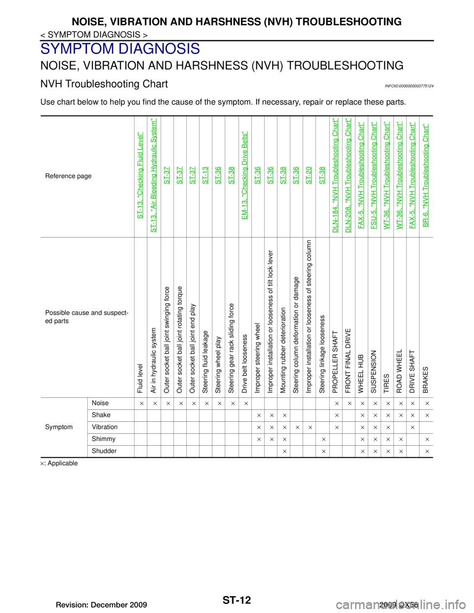
NVH Troubleshooting ChartINFOID:0000000003775124
Use chart below to help you find the cause of the symp tom. If necessary, repair or replace these parts.
×: ApplicableReference page
ST-13, "Checking Fluid Level"
ST-13, "Air Bleeding Hydraulic System"
ST-37ST-37ST-37ST-13ST-36ST-38
EM-13, "Checking Drive Belts"
ST-36ST-36ST-38ST-36ST-20ST-38
DLN-184, "NVH Troubleshooting Chart"DLN-208, "NVH Troubleshooting Chart"FAX-5, "NVH Troubleshooting Chart"FSU-5, "NVH Troubleshooting Chart"WT-36, "NVH Troubleshooting Chart"WT-36, "NVH Troubleshooting Chart"FAX-5, "NVH Troubleshooting Chart"BR-6, "NVH Troubleshooting Chart"
Possible cause and suspect-
ed parts
Fluid level
Air in hydraulic system
Outer socket ball joint swinging force
Outer socket ball joint rotating torque
Outer socket ball joint end play
Steering fluid leakage
Steering wheel play
Steering gear rack sliding force
Drive belt looseness
Improper steering wheel
Improper installation or looseness of tilt lock lever
Mounting rubber deterioration
Steering column deformation or damage
Improper installation or looseness of steering column
Steering linkage looseness
PROPELLER SHAFT
FRONT FINAL DRIVE
WHEEL HUB
SUSPENSION
TIRES
ROAD WHEEL
DRIVE SHAFT
BRAKES
Symptom
Noise
× × ××××× × × ××××××× ×
Shake ××× × ××××× ×
Vibration ××××× × ××× ×
Shimmy ××× × ×××× ×
Shudder × × ×××× ×
Revision: December 20092009 QX56
Page 3606 of 4171

STEERING WHEELST-15
< ON-VEHICLE REPAIR >
C
DE
F
H I
J
K L
M A
B
ST
N
O P
ON-VEHICLE REPAIR
STEERING WHEEL
On-Vehicle Inspection and ServiceINFOID:0000000004187602
CHECKING CONDITION OF INSTALLATION
Check installation condition of steering gear assemb ly, front suspension, axle and steering column.
Check if movement exists when steering wheel is mo ved up and down, to the left and right and to the axial
direction.
Check if the nuts for steering gear assembly are loose. Refer to ST-23, "Removal and Installation"
.
CHECKING STEERING WHEEL PLAY
1. Turn tires straight ahead, start engine, then turn steer ing wheel to the left and right lightly, and measure
steering wheel movement on the outer circumference when steering wheel is turned up to the point where
tires start moving.
CHECKING NEUTRAL POSITION ON STEERING WHEEL
Check neutral position on steering wheel after confirming that front wheel alignment is correct. Refer to FSU-
6, "Front Wheel Alignment".
1. Turn tires straight ahead, check if st eering wheel is in the neutral position.
2. If it is not in the neutral position, remo ve steering wheel and reinstall it correctly.
3. If the neutral position cannot be attained by repositi oning the steering wheel two teeth or less on steering
stem, loosen tie-rod lock nuts of steering outer socket s, then adjust tie-rods by the same amount in the
opposite direction.
CHECKING STEERING WHEEL TURNING FORCE
1. Park vehicle on a level, dry surface and set parking brake.
2. Start engine.
3. Bring power steering fluid up to operating temperature of 60 °– 80 °C (140 °– 176 °F).
4. Tires need to be inflated to specified pressure. Refer to WT-45, "Tire"
.
End play of the axial direction for steering wheel : Refer to
ST-
36, "Steering
Wheel"
LGIA0024E
Steering wheel play on the outer circumference : Refer to ST-36, "Steering
Wheel"
Revision: December 20092009 QX56
Page 3652 of 4171

TM-4
Precaution for Supplemental Restraint System
(SRS) "AIR BAG" and "SEAT BELT PRE-TEN-
SIONER" ................................................................
174
Precaution Necessary for Steering Wheel Rota-
tion After Battery Disconnect .................................
174
Precaution for On Board Diagnosis (OBD) System
of A/T and Engine ..................................................
175
Precaution .............................................................175
Service Notice or Precaution .................................176
PREPARATION ..........................................177
PREPARATION .............................................. .177
Special Service Tool ............................................ ..177
Commercial Service Tool ......................................178
ON-VEHICLE MAINTENANCE ..................179
A/T FLUID ....................................................... .179
Checking the A/T Fluid (ATF) .............................. ..179
Changing the A/T Fluid (ATF) ................................181
A/T FLUID COOLER ........................................183
A/T Fluid Cooler Cleaning ................................... ..183
Inspection ..............................................................185
STALL TEST ....................................................186
Inspection and Judgment .................................... ..186
LINE PRESSURE TEST ..................................188
Inspection and Judgment .................................... ..188
ROAD TEST .....................................................190
Description ........................................................... ..190
Check Before Engine Is Started ............................190
Check At Idle .........................................................190
Cruise Test - Part 1 ...............................................191
Cruise Test - Part 2 ...............................................193
Cruise Test - Part 3 ...............................................194
Vehicle Speed When Shifting Gears .....................194
Vehicle Speed When Performing and Releasing
Complete Lock-up .................................................
194
A/T POSITION .................................................195
Adjustment of A/T Position .................................. ..195
Checking of A/T Position .......................................195
ON-VEHICLE REPAIR ............................. ..196
SHIFT CONTROL SYSTEM ........................... .196
A/T Shift Selector Removal and Installation ........ ..196
AIR BREATHER HOSE ...................................197
2WD ........................................................................ ..197
2WD : Removal and Installation ............................197
4WD ........................................................................ ..197
4WD : Removal and Installation ............................197
OIL PAN ...........................................................201
Oil Pan ................................................................. .201
CONTROL VALVE WITH TCM ........................203
Control Valve with TCM and A/T Fluid Tempera-
ture Sensor 2 ....................................................... .
203
REAR OIL SEAL ..............................................212
Rear Oil Seal ........................................................ .212
FLUID COOLER SYSTEM ...............................213
Exploded View ..................................................... .213
Removal and Installation .......................................213
REMOVAL AND INSTALLATION .............214
TRANSMISSION ASSEMBLY ........................ ..214
Removal and Installation (2WD) .......................... .214
Removal and Installation (4WD) ...........................216
DISASSEMBLY AND ASSEMBLY ...........220
OVERHAUL .................................................... ..220
Component .......................................................... .220
Oil Channel ...........................................................227
Location of Adjusting Shims, Needle Bearings,
Thrust Washers and Snap Rings ......................... .
229
DISASSEMBLY .............................................. ..232
Disassembly ......................................................... .232
REPAIR FOR COMPONENT PARTS ..............249
Oil Pump .............................................................. .249
Front Sun Gear, 3rd One-Way Clutch ...................251
Front Carrier, Input Clutch, Rear Internal Gear .....253
Mid Sun Gear, Rear Sun Gear, High and Low Re-
verse Clutch Hub ..................................................
258
High and Low Reverse Clutch ..............................263
Direct Clutch .........................................................265
ASSEMBLY .................................................... ..268
Assembly (1) ........................................................ .268
Adjustment ............................................................281
Assembly (2) .........................................................283
SERVICE DATA AND SPECIFICATIONS
(SDS) ............... ..........................................
290
SERVICE DATA AND SPECIFICATIONS
(SDS) .............................................................. ..
290
General Specification ........................................... .290
Vehicle Speed at Which Gear Shifting Occurs .....290
Vehicle Speed at Which Lock-up Occurs/Releas-
es ..........................................................................
291
Stall Speed ............................................................291
Line Pressure ........................................................291
Input Speed Sensor ..............................................291
Output Speed Sensor ...........................................291
Reverse Brake ......................................................291
Total End Play .......................................................292
Torque Converter .................................................
Revision: December 20092009 QX56