engine oil INFINITI QX56 2009 Factory Manual PDF
[x] Cancel search | Manufacturer: INFINITI, Model Year: 2009, Model line: QX56, Model: INFINITI QX56 2009Pages: 4171, PDF Size: 84.65 MB
Page 1865 of 4171

EM-42
< ON-VEHICLE REPAIR >
FUEL INJECTOR AND FUEL TUBE
• Lubricate O-ring with new engine oil.
• Do not clean O-ring with solvent.
• Make sure that O-ring and its mating part are free of foreign material.
• When installing O-ring, be careful not to scratch it with tool or fingernails. Also be careful not to
twist or stretch O-ring. If O-ring was stretc hed while it was being attached, do not insert it
quickly into fuel tube.
• Insert O-ring straight into fuel tube. Do not angle or twist it.
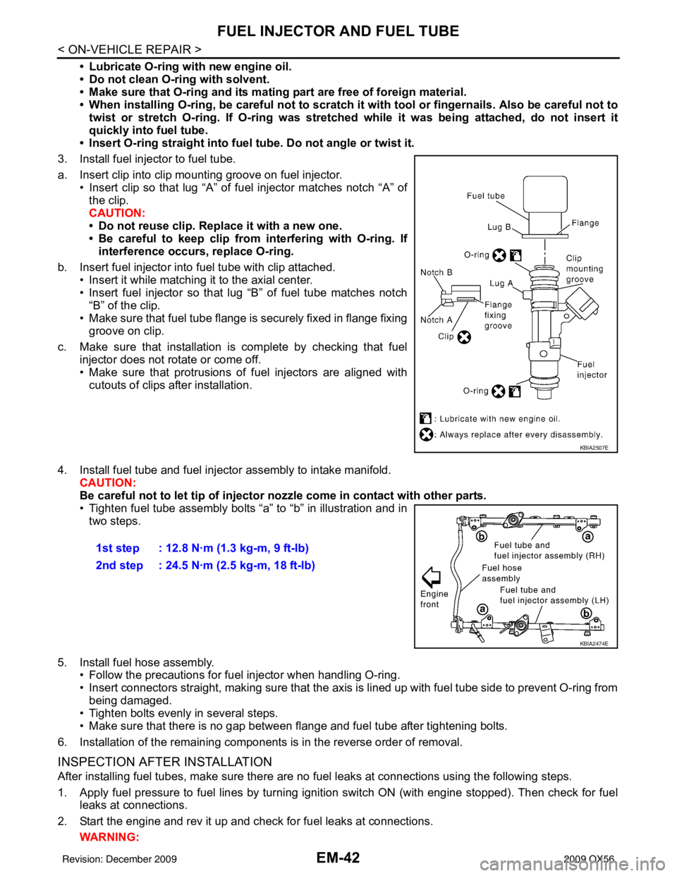
3. Install fuel injector to fuel tube.
a. Insert clip into clip mounting groove on fuel injector. • Insert clip so that lug “A” of fuel injector matches notch “A” ofthe clip.
CAUTION:
• Do not reuse clip. Replace it with a new one.
• Be careful to keep clip from interfering with O-ring. Ifinterference occurs, replace O-ring.
b. Insert fuel injector into fuel tube with clip attached. • Insert it while matching it to the axial center.
• Insert fuel injector so that lug “B” of fuel tube matches notch
“B” of the clip.
• Make sure that fuel tube flange is securely fixed in flange fixing groove on clip.
c. Make sure that installation is complete by checking that fuel injector does not rotate or come off.
• Make sure that protrusions of fuel injectors are aligned withcutouts of clips after installation.
4. Install fuel tube and fuel injector assembly to intake manifold. CAUTION:
Be careful not to let tip of injector nozzle come in contact with other parts.
• Tighten fuel tube assembly bolts “a” to “b” in illustration and in
two steps.
5. Install fuel hose assembly. • Follow the precautions for fuel injector when handling O-ring.
• Insert connectors straight, making sure that the axis is lined up with fuel tube side to prevent O-ring from
being damaged.
• Tighten bolts evenly in several steps.
• Make sure that there is no gap between flange and fuel tube after tightening bolts.
6. Installation of the remaining components is in the reverse order of removal.
INSPECTION AFTER INSTALLATION
After installing fuel tubes, make sure there are no fuel leaks at connections using the following steps.
1. Apply fuel pressure to fuel lines by turning ignition switch ON (with engine stopped). Then check for fuel leaks at connections.
2. Start the engine and rev it up and check for fuel leaks at connections. WARNING:
KBIA2507E
1st step : 12.8 N·m (1.3 kg-m, 9 ft-lb)
2nd step : 24.5 N·m (2.5 kg-m, 18 ft-lb)
KBIA2474E
Revision: December 20092009 QX56
Page 1868 of 4171

TIMING CHAINEM-45
< ON-VEHICLE REPAIR >
C
DE
F
G H
I
J
K L
M A
EM
NP
O
Removal and InstallationINFOID:0000000005885887
NOTE:
• To remove timing chain and associated parts, start with those on the LH bank. The procedure for removing
parts on the RH bank is omitted because it is t he same as that for removal on the LH bank.
• To install timing chain and associated parts, start with those on the RH bank. The procedure for installing parts on the LH bank is omitted because it is t he same as that for installation on the RH bank.
REMOVAL
1. Remove the engine assembly from the vehicle. Refer to EM-78, "Removal and Installation".
2. Remove the following components and related parts: • Drive belt auto tensioner and idler pulley. Refer to EM-13, "
Removal and Installation".
• Thermostat housing and water hose. Refer to CO-22, "
Removal and Installation".
• Power steering oil pump bracket. Refer to ST-26, "
Removal and Installation".
• Oil pan (lower), (upper) and oil strainer. Refer to EM-33, "
Removal and Installation".
• Rocker cover. Refer to EM-38, "
Removal and Installation".
• Generator and generator bracket. Refer to CHG-20, "
Removal and Installation".
• Water pump. Refer to CO-20, "
Exploded View".
3. Disconnect and remove the camshaft position sensor.
4. Disconnect and remove the intake valve ti ming control position sensor (RH and LH).
5. Disconnect and remove the intake valve timing control solenoid valve (RH and LH).
6. Remove the Intake valve timing control solenoid valve cover (RH) (A) and Intake valve timing control solenoid valve cover
(LH) (B) as follows:
a. Loosen and remove the bolts in reverse order as shown.
b. Cut the liquid gasket and remove the covers using Tool.
CAUTION:
Do not damage mating surfaces.
1. Camshaft sprocket LH bank EXH 2. Camshaft sprocket LH bank INT (VTC)3. Camshaft sprocket RH bank INT
(VTC)
4. Camshaft sprocket RH bank EXH 5. Front cover 6. Intake valve timing control solenoid
valve (RH)
7. Intake valve timing control solenoid valve cover (RH) 8. Intake valve timing control position
sensor (RH) 9. Intake valve timing control position
sensor (LH)
10. Intake valve timing control solenoid valve cover (LH) 11. Camshaft position
sensor (PHASE) 12 Cran kshaft pulley bolt
13. Crankshaft pulley 14. Chain tensioner cover 15. Front oil seal
16. Intake valve timing control solenoid valve (RH) 17. O-ring
18. Timing chain tension guide RH bank
19. Timing chain slack guide (RH) 20. Timing chain RH bank 21. Timing chain LH bank
22. Chain tensioner (RH) 23. Timing chain slack guide LH bank 24. Timing chain tension guide LH bank
25. Chain tensioner (LH) 26. O-ring 27. Bracket
28. Oil pump drive spacer 29. Oil pump assembly 30. Crankshaft sprockets
A. To crankshaft B. To camshaft LH bank EXH C. To camshaft LH bank INT (VTC)
D. To camshaft RH bank INT (VTC) E. To camshaft RH bank EXH F. Apply sealant to mating side
G. Refer to EM-45
Tool number : KV10111100 (J-37228)
AWBIA0815ZZ
Revision: December 20092009 QX56
Page 1873 of 4171

EM-50
< ON-VEHICLE REPAIR >
TIMING CHAIN
7. Install the oil pump drive spacer as follows:• Install so that the front mark on the front edge of the oil pumpdrive spacer faces the front of the engine.
• Insert the oil pump drive spacer according to the directions of the crankshaft key and the two flat surfaces of the oil pump
inner rotor.
• If the positional relationship does not allow the insertion, rotate the oil pump inner rotor to allow the oil pump drive spacer to
be inserted.
8. Install the front oil seal using suitable tool. CAUTION:
Do not scratch or make burrs on the circumference of the
oil seal.
9. Install the chain tensioner cover. • Apply liquid gasket as shown.
Use Genuine RTV Silicone Seal ant or equivalent. Refer to
GI-15, "
Recommended Chemical Products and Sealants".
10. Install the front cover as follows:
a. Install a new O-ring on the cylinder block.
KBIA2490E
PBIC0059E
KBIA2547E
KBIA2516E
Revision: December 20092009 QX56
Page 1874 of 4171

TIMING CHAINEM-51
< ON-VEHICLE REPAIR >
C
DE
F
G H
I
J
K L
M A
EM
NP
O
b. Apply liquid gasket as shown.
Use Genuine RTV Silicone Seal ant or equivalent. Refer to
GI-15, "
Recommended Chemical Products and Sealants".
c. Check again that the timing alignment marks on the timing chain and on each sprocket are aligned. Then install the front cover.
d. Install the bolts in the numerical order shown.
e. After tightening, re-tighten to the specified torque. CAUTION:
Be sure to wipe off any excessive liquid gasket leaking onto
surface mating with oil pan.
11. Install the Intake valve timing control solenoid valve cover (RH) (A) and Intake valve timing control solenoid valve cover (LH) (B)
as follows:
• Cross mark that can not be seen after assembly (C)
a. Apply liquid gasket (D) as shown. Use Genuine RTV Silicone Seal ant or equivalent. Refer to
GI-15, "
Recommended Chemical Products and Sealants".
CAUTION:
The start and end of the appl ication of the liquid gasket
should be crossed at a position (C) that cannot be seen
after attaching the chain case cover.
b. Install the bolts and tighten them to specification in the numeri- cal order shown.
• A: Intake valve timing control solenoid valve cover (RH)
• B: Intake valve timing control solenoid valve cover (LH)
12. Install the crankshaft pulley. • Install the key of the crankshaft.
• Insert the pulley by lightly tapping it.
CAUTION:
Do not tap pulley on the side surface where th e belt is installed (outer circumference).
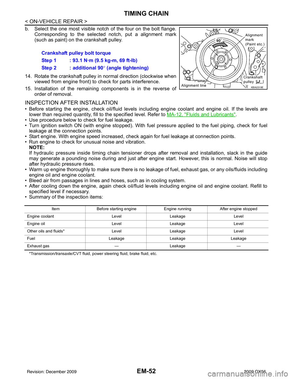
13. Tighten the crankshaft pulley bolt. • Lock the crankshaft using suitable tool, then tighten the bolt.
• Perform the following steps for angular tightening:
a. Apply engine oil onto the threaded parts of the bolt and seating area.
KBIA2517E
M6 × 50 mm (1.97 in) : No. 1, 20, 25, 26, 27
M6 × 80 mm (3.15 in) : No. 4, 5, 7
M6 × 20 mm (0.79 in) : Except the above
KBIA2478E
D : 2.6 - 3.6 mm (0.102 - 0.142 in) dia.
WBIA0800E
AWBIA0815ZZ
Revision: December 20092009 QX56
Page 1875 of 4171

EM-52
< ON-VEHICLE REPAIR >
TIMING CHAIN
b. Select the one most visible notch of the four on the bolt flange.Corresponding to the selected notch, put a alignment mark
(such as paint) on the crankshaft pulley.
14. Rotate the crankshaft pulley in normal direction (clockwise when viewed from engine front) to check for parts interference.
15. Installation of the remaining components is in the reverse of order of removal.
INSPECTION AFTER INSTALLATION
• Before starting the engine, check oil/fluid levels in cluding engine coolant and engine oil. If the levels are
lower than required quantity, fill to the specified level. Refer to MA-12, "
Fluids and Lubricants".
• Use procedure below to check for fuel leakage.
• Turn ignition switch ON (with engine stopped). With fuel pressure applied to the fuel piping, check for fuel leakage at the connection points.
• Start engine. With engine speed increased, che ck again for fuel leakage at connection points.
• Run engine to check for unusual noise and vibration. NOTE:
If hydraulic pressure inside timing chain tensioner drops after removal and installation, slack in the guide
may generate a pounding noise during and just after engine start. However, this is normal. Noise will stop
after hydraulic pressure rises.
• Warm up engine thoroughly to make sure there is no leakage of fuel, exhaust gas, or any oils/fluids including engine oil and engine coolant.
• Bleed air from passages in lines and hoses, such as in cooling system.
• After cooling down the engine, again check oil/fluid levels including engine oil and engine coolant. Refill to
specified level if necessary.
• Summary of the inspection items:
*Transmission/transaxle/CVT fluid, power steering fluid, brake fluid, etc.
Crankshaft pulley bolt torque
Step 1 : 93.1 N·m (9.5 kg-m, 69 ft-lb)
Step 2 : additional 90 ° (angle tightening)
KBIA2519E
Item Before starting engine Engine runningAfter engine stopped
Engine coolant LevelLeakage Level
Engine oil LevelLeakage Level
Other oils and fluids* LevelLeakage Level
Fuel LeakageLeakageLeakage
Exhaust gas —Leakage —
Revision: December 20092009 QX56
Page 1885 of 4171

EM-62
< ON-VEHICLE REPAIR >
CAMSHAFT
5. Install the camshaft sprockets using the following procedure:• A: LH bank shown
a. Install the camshaft sprockets aligning them with the matching marks painted on the timing chain (B) and the camshaft sprock-
ets (C) before removal. Align the camshaft sprocket key groove
with the dowel pin on the camshaft front edge at the same time.
Then temporarily tighten camshaft sprocket bolts.
• Install the intake (VTC) (A) and exhaust (B) side camshaft
sprockets by selectively using the groove of the dowel pin
according to the bank for the exhaust (B) side camshaft
sprockets. (Common part used for both exhaust banks.)
NOTE:
Use the groove marked "R" for RH bank and "L" for LH bank.
b. Lock the hexagonal part of the camshaft in the same way as for removal, and tighten the camshaft sprocket bolts.
c. Check again that the timing alignment mark on the timing chain and on each sprocket are aligned.
6. Install the chain tensioner using the following procedure: NOTE:
LH is shown.
a. Install the chain tensioner. • Compress the plunger and hold it using a stopper pin wheninstalling.
• Loosen the slack guide side timing chain by rotating the cam- shaft hexagonal part if mounting space is small.
b. Remove the stopper pin and release the plunger, and then apply tension to the timing chain.
c. Install the chain tensioner cover onto the front cover. • Apply liquid gasket as shown.
Use Genuine RTV Silicone Seal ant or equivalent. Refer to
GI-15, "
Recommended Chemical Products and Sealants".
7. Check and adjust valve clearances. Refer to EM-18, "
Va l v e
Clearance".
8. Installation of the remaining components is in the reverse order of removal.
Inspection after InstallationINFOID:0000000005885890
INSPECTION OF CAMSHAFT SPROCKET (INT) OIL GROOVE
WARNING:
• Check when engine is cold so as to pr event burns from any splashing engine oil.
CAUTION:
AWBIA0152ZZ
AWBIA0151ZZ
Chain tensioner bolts : 6.9 N·m (0.70 kg-m, 61 in-lb)
Chain tensioner cover
bolts : 9.0 N·m (0.92 kg-m, 80 in-lb)KBIA2479E
KBIA2547E
Revision: December 20092009 QX56
Page 1886 of 4171

CAMSHAFTEM-63
< ON-VEHICLE REPAIR >
C
DE
F
G H
I
J
K L
M A
EM
NP
O
• Perform this inspection only when
DTC P0011 is detected in self-diagnostic results of CONSULT III
and it is directed according to inspecti on procedure of EC section. Refer to EC-87, "
On Board Diag-
nosis Logic".
1. Check engine oil level. Refer to LU-8, "
Inspection".
2. Perform the following procedure so as to prevent the engine from being unintentionally started while checking.
a. Release fuel pressure. Refer to EC-487, "
Fuel Pressure Check".
b. Disconnect ignition coil and injector harness connectors if practical.
3. Remove IVT control solenoid valve.
4. Crank engine, and then make sure that engine oil comes out from IVT control cover oil hole. End cranking after checking.
WARNING:
Be careful not to touch rotating parts (drive be lts, idler pulley, and crankshaft pulley, etc.).
CAUTION:
• Engine oil may squirt from IVT control solenoid valve installation hole during cranking. Use a
shop cloth to prevent engine oil from splash ing on worker, engine components and vehicle.
• Do not allow engine oil to get on rubber components such as drive belts or engine mount insula- tors. Immediately wipe off any splashed engine oil.
5. Clean oil groove between oil strainer and IVT control solenoid valve if engine oil does not come out from IVT control valve cover oil hole. Refer to LU-7, "
Schematic".
6. Remove components between IVT control solenoid valve and camshaft sprocket (INT), and then check each oil groove for clogging.
• Clean oil groove if necessary.
7. After inspection, installation of the remaining components is in the reverse order of removal.
Revision: December 20092009 QX56
Page 1887 of 4171

EM-64
< ON-VEHICLE REPAIR >
OIL SEAL
OIL SEAL
Removal and Installation of Valve Oil SealINFOID:0000000005885891
REMOVAL
1. Remove the camshaft relating to the valve oil seal to be removed. Refer to EM-53, "Removal and Installa-
tion".
2. Remove the valve lifters. Refer to EM-53, "
Exploded View".
• Correctly identify the location where each part is removed from. Keep parts organized to avoid mixing
them up.
3. Turn the crankshaft until the cylinder requiring new oil seals is at TDC. This will prevent the valve from
dropping into the cylinder.
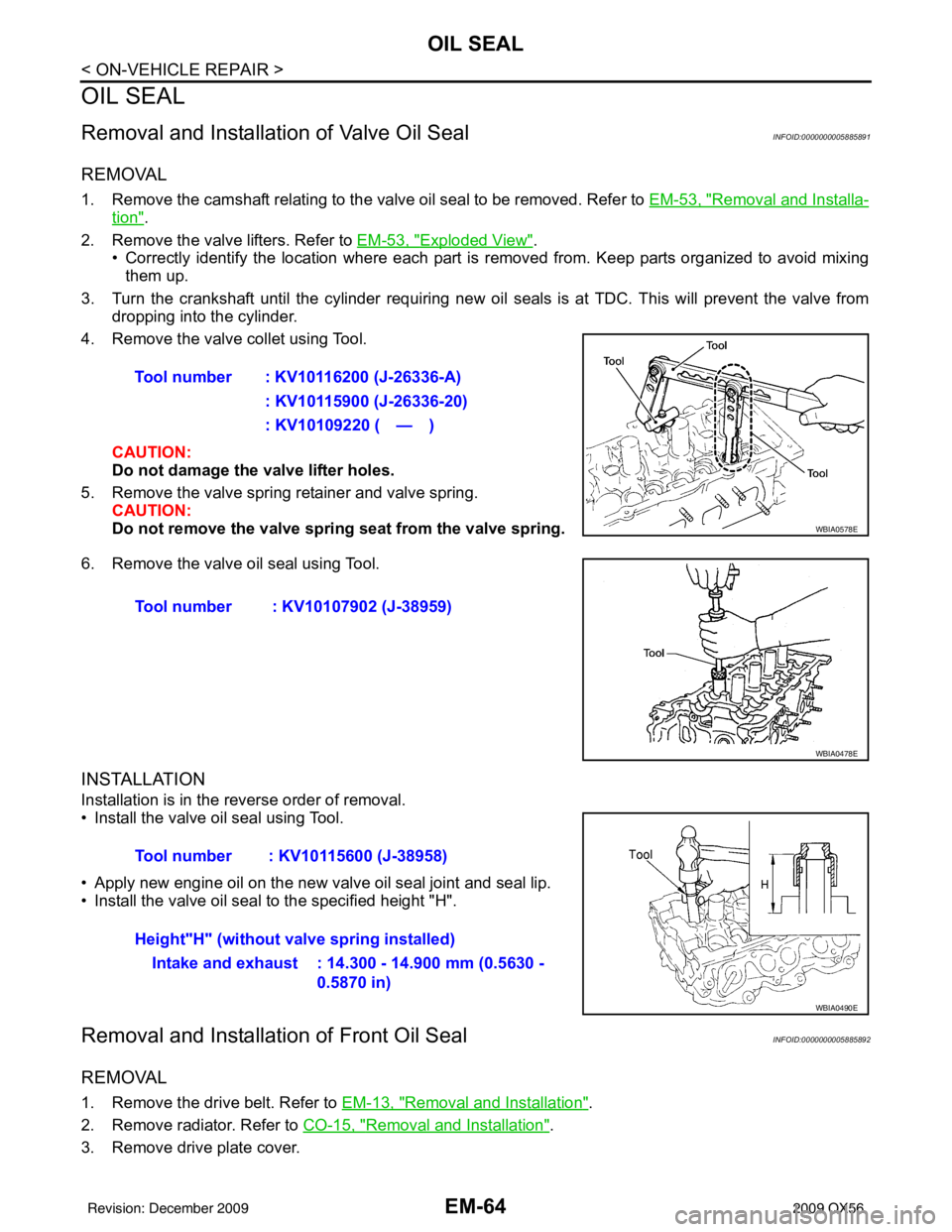
4. Remove the valve collet using Tool.
CAUTION:
Do not damage the valve lifter holes.
5. Remove the valve spring retainer and valve spring. CAUTION:
Do not remove the valve spring seat from the valve spring.
6. Remove the valve oil seal using Tool.
INSTALLATION
Installation is in the reverse order of removal.
• Install the valve oil seal using Tool.
• Apply new engine oil on the new valve oil seal joint and seal lip.
• Install the valve oil seal to the specified height "H".
Removal and Installation of Front Oil SealINFOID:0000000005885892
REMOVAL
1. Remove the drive belt. Refer to EM-13, "Removal and Installation".
2. Remove radiator. Refer to CO-15, "
Removal and Installation".
3. Remove drive plate cover. Tool number : KV10116200 (J-26336-A)
: KV10115900 (J-26336-20)
: KV10109220 ( — )
WBIA0578E
Tool number : KV10107902 (J-38959)
WBIA0478E
Tool number : KV10115600 (J-38958)
Height"H" (without valve spring installed)Intake and exhaust : 14.300 - 14.900 mm (0.5630 - 0.5870 in)
WBIA0490E
Revision: December 20092009 QX56
Page 1888 of 4171

OIL SEALEM-65
< ON-VEHICLE REPAIR >
C
DE
F
G H
I
J
K L
M A
EM
NP
O
4. Lock crankshaft using Tool (A).
5. Matchmark crankshaft pulley bolt flange and crankshaft pulley for installation.
6. Remove the crankshaft pulley bolt and crankshaft pulley from
the crankshaft using suitable tool.
7. Remove the front oil seal using suitable tool. CAUTION:
Do not damage front cover and oil pump drive spacer.
INSTALLATION
1. Apply new engine oil to both the oil seal lip and dust seal lip of the new front oil seal.
2. Install the front oil seal.
• Install the front oil seal so that each seal lip is oriented asshown.Tool number : — (J-47245)
LBIA0455E
KBIA2477E
SBIA0359E
SEM715A
Revision: December 20092009 QX56
Page 1889 of 4171

EM-66
< ON-VEHICLE REPAIR >
OIL SEAL
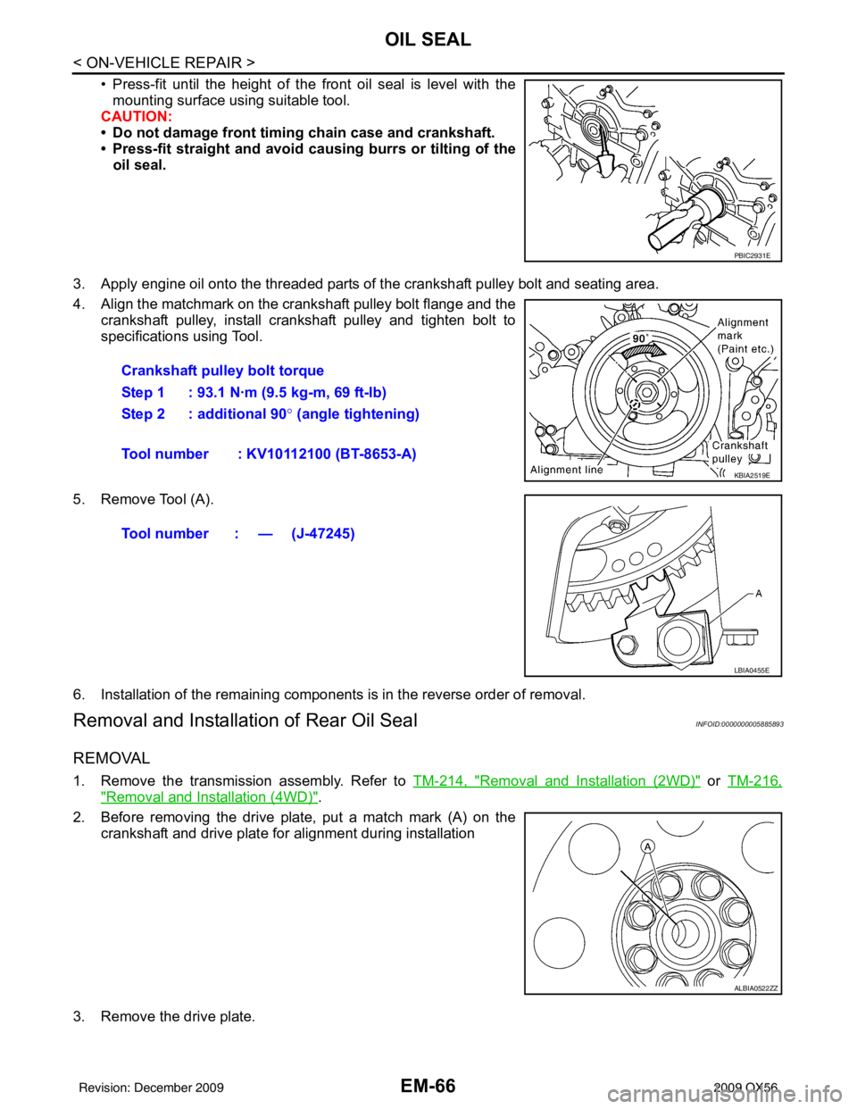
• Press-fit until the height of the front oil seal is level with themounting surface using suitable tool.
CAUTION:
• Do not damage front timing chain case and crankshaft.
• Press-fit straight and avoid cau sing burrs or tilting of the
oil seal.
3. Apply engine oil onto the threaded parts of the crankshaft pulley bolt and seating area.
4. Align the matchmark on the crankshaft pulley bolt flange and the crankshaft pulley, install crankshaft pulley and tighten bolt to
specifications using Tool.
5. Remove Tool (A).
6. Installation of the remaining components is in the reverse order of removal.
Removal and Installation of Rear Oil SealINFOID:0000000005885893
REMOVAL
1. Remove the transmission assembly. Refer to TM-214, "Removal and Installation (2WD)" or TM-216,
"Removal and Installation (4WD)".
2. Before removing the drive plate, put a match mark (A) on the crankshaft and drive plate for alignment during installation
3. Remove the drive plate.
PBIC2931E
Crankshaft pulley bolt torque
Step 1 : 93.1 N·m (9.5 kg-m, 69 ft-lb)
Step 2 : additional 90 ° (angle tightening)
Tool number : KV10112100 (BT-8653-A)
KBIA2519E
Tool number : — (J-47245)
LBIA0455E
ALBIA0522ZZ
Revision: December 20092009 QX56