brake fluid INFINITI QX56 2009 Factory Service Manual
[x] Cancel search | Manufacturer: INFINITI, Model Year: 2009, Model line: QX56, Model: INFINITI QX56 2009Pages: 4171, PDF Size: 84.65 MB
Page 8 of 4171
2009
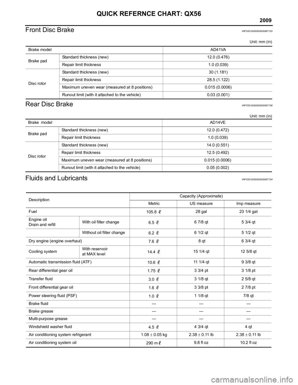
QUICK REFERNCE CHART: QX56
Front Disc Brake
INFOID:0000000005987155
Unit: mm (in)
Rear Disc BrakeINFOID:0000000005987156
Unit: mm (in)
Fluids and LubricantsINFOID:0000000005987154
Brake model AD41VA
Brake pad Standard thickness (new) 12.0 (0.476)
Repair limit thickness 1.0 (0.039)
Disc rotor Standard thickness (new) 30 (1.181)
Repair limit thickness 28.5 (1.122)
Maximum uneven wear (measured at 8 positions) 0.015 (0.0006)
Runout limit (with it attached to the vehicle) 0.03 (0.001)
Brake model
AD14VE
Brake pad Standard thickness (new) 12.0 (0.472)
Repair limit thickness 1.0 (0.039)
Disc rotor Standard thickness (new) 14.0 (0.551)
Repair limit thickness 12.5 (0.492)
Maximum uneven wear (measured at 8 positions) 0.015 (0.0006)
Runout limit (with it attached to the vehicle) 0.05 (0.002)
Description
Capacity (Approximate)
Metric US measure Imp measure
Fuel 105.8 28 gal 23 1/4 gal
Engine oil
Drain and refill With oil filter change
6.5 6 7/8 qt 5 3/4 qt
Without oil filter change 6.2 6 1/2 qt 5 1/2 qt
Dry engine (engine overhaul) 7.6 8 qt 6 3/4 qt
Cooling system With reservoir
at MAX level
14.4
15 1/4 qt 12 5/8 qt
Automatic transmission fluid (ATF) 10.6 11 1/4 qt 9 3/8 qt
Rear differential gear oil 1.75 3 3/4 pt 3 1/8 pt
Transfer fluid 3.0 3 1/8 qt 2 5/8 qt
Front differential gear oil 1.6 3 3/8 pt 2 7/8 pt
Power steering fluid (PSF) 1.0 1 1/8 qt 7/8 qt
Brake fluid — — —
Brake grease — — —
Multi-purpose grease — — —
Windshield washer fluid 4.5 4 3/4 qt 4 qt
Air conditioning system refrigerant 1.08 ± 0.05 kg 2.38 ± 0.11 lb 2.38 ± 0.11 lb
Air conditioning system oil 290 m9.8 fl oz 10.2 fl oz
Page 431 of 4171

BR-1
BRAKES
C
DE
G H
I
J
K L
M
SECTION BR
A
B
BR
N
O P
CONTENTS
BRAKE SYSTEM
PRECAUTION ....... ........................................3
PRECAUTIONS .............................................. .....3
Precaution for Supplemental Restraint System
(SRS) "AIR BAG" and "SEAT BELT PRE-TEN-
SIONER" ............................................................. ......
3
Precaution Necessary for Steering Wheel Rota-
tion After Battery Disconnect ............................... ......
3
Precaution for Brake System ....................................4
PREPARATION ............................................5
PREPARATION .............................................. .....5
Special Service Tool ........................................... ......5
Commercial Service Tool ..........................................5
FUNCTION DIAGNOSIS ...............................6
NOISE, VIBRATION AND HARSHNESS
(NVH) TROUBLESHOOTING ........................ .....
6
NVH Troubleshooting Chart ................................ ......6
BASIC INSPECTION ....................................7
FRONT DISC B RAKE .................................... .....7
BRAKE PAD .......................................................... ......7
BRAKE PAD : Inspection ..........................................7
DISC ROTOR ......................................................... ......7
DISC ROTOR : Inspection ........................................7
REAR DISC BRAKE ...................................... .....9
BRAKE PAD .......................................................... ......9
BRAKE PAD : Inspection ..........................................9
DISC ROTOR ......................................................... ......9
DISC ROTOR : Inspection ........................................9
BRAKE BOOSTER ............................................10
Inspection ............................................................ ....10
VACUUM LINES ............................................. ....11
Inspection ............................................................ ....11
BRAKE MASTER CYLINDER ..........................12
On Board Inspection ................................................12
BRAKE TUBE AND HOSE ...............................13
Hydraulic Circuit ......................................................13
FRONT BRAKE ..................................................... ....13
FRONT BRAKE : Inspection ......................... ...........13
REAR BRAKE ........................................................ ....14
REAR BRAKE : Inspection ........................ ..............14
ON-VEHICLE MAINTEN ANCE ....................15
BRAKE PEDAL .................................................15
Inspection and Adjustment .................................. ....15
BRAKE FLUID ..................................................17
On Board Inspection ............................................ ....17
Drain and Refill ........................................................17
Bleeding Brake System ...........................................17
ON-VEHICLE REPAIR .................................19
BRAKE PEDAL .................................................19
Removal and Installation ..................................... ....19
BRAKE TUBE AND HOSE ...............................21
Hydraulic Circuit ......................................................21
Removal and Installation of Front Brake Piping
and Brake Hose .......................................................
21
Removal and Installation of Rear Brake Piping
and Brake Hose .......................................................
22
Inspection After Installation .....................................23
BRAKE MASTER CYLINDER ..........................25
Removal and Installation .........................................25
BRAKE BOOSTER ...........................................26
Removal and Installation ..................................... ....26
VACUUM LINES ...............................................28
Revision: December 20092009 QX56
Page 434 of 4171
BR-4
< PRECAUTION >
PRECAUTIONS
5. When the repair work is completed, return the ignition switch to the ″LOCK ″ position before connecting
the battery cables. (At this time, the steering lock mechanism will engage.)
6. Perform a self-diagnosis check of a ll control units using CONSULT-III.
Precaution for Brake SystemINFOID:0000000003772409
• Always use recommended brake fluid. Refer to MA-12, "Fluids and Lubricants".
• Do not reuse drained brake fluid.
• Be careful not to splash brake fluid on painted areas.
• To clean or wash all parts of master cylinder, disc brake caliper and wheel cylinder, use clean brake fluid.
• Do not use mineral oils such as gasoline or kerosene. They will ruin rubber parts of the hydraulic system.
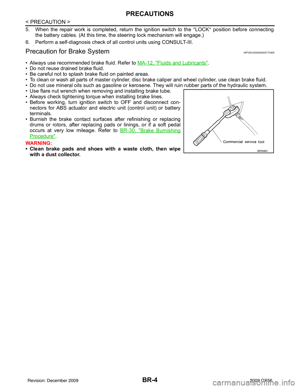
• Use flare nut wrench when removing and installing brake tube.
• Always check tightening torque when installing brake lines.
• Before working, turn ignition switch to OFF and disconnect con- nectors for ABS actuator and electric unit (control unit) or battery
terminals.
• Burnish the brake contact surfaces after refinishing or replacing drums or rotors, after replacing pads or linings, or if a soft pedal
occurs at very low mileage. Refer to BR-30, "
Brake Burnishing
Procedure".
WARNING:
• Clean brake pads and shoes wi th a waste cloth, then wipe
with a dust collector.
SBR686C
Revision: December 20092009 QX56
Page 443 of 4171
BRAKE TUBE AND HOSEBR-13
< BASIC INSPECTION >
C
DE
G H
I
J
K L
M A
B
BR
N
O P
BRAKE TUBE AND HOSE
Hydraulic CircuitINFOID:0000000004042327
CAUTION:
• All hoses and piping (tubes) must be fr ee from excessive bending, twisting and pulling.
• Make sure there is no interference with other parts when turning the steering wheel both clockwise
and counterclockwise.
• The brake piping is an important safety part. If a brake fluid leak is detected, always disassemble the
parts. Replace applicable part with a new one, if necessary.
• Be careful not to splash brake fluid on painted areas; it may cause paint damage. If brake fluid is
splashed on painted areas, wash it away with water immediately.
• Do not bend or twist brake hose sharply, or strongly pull it.
• When removing components, cover connections so that no dirt, dust, or other foreign matter gets in.
• Refill with new specified brake fluid. Refer to MA-12, "
Fluids and Lubricants".
• Do not reuse drained brake fluid.
FRONT BRAKE
FRONT BRAKE : InspectionINFOID:0000000003772422
INSPECTION AFTER REMOVAL
CAUTION:
Brake tubes and hoses are important safety parts. Always disassemble the parts and retighten their fit-
tings, if a brake fluid leak is det ected. Replace applicable part with a new one, if damaged part is
detected.
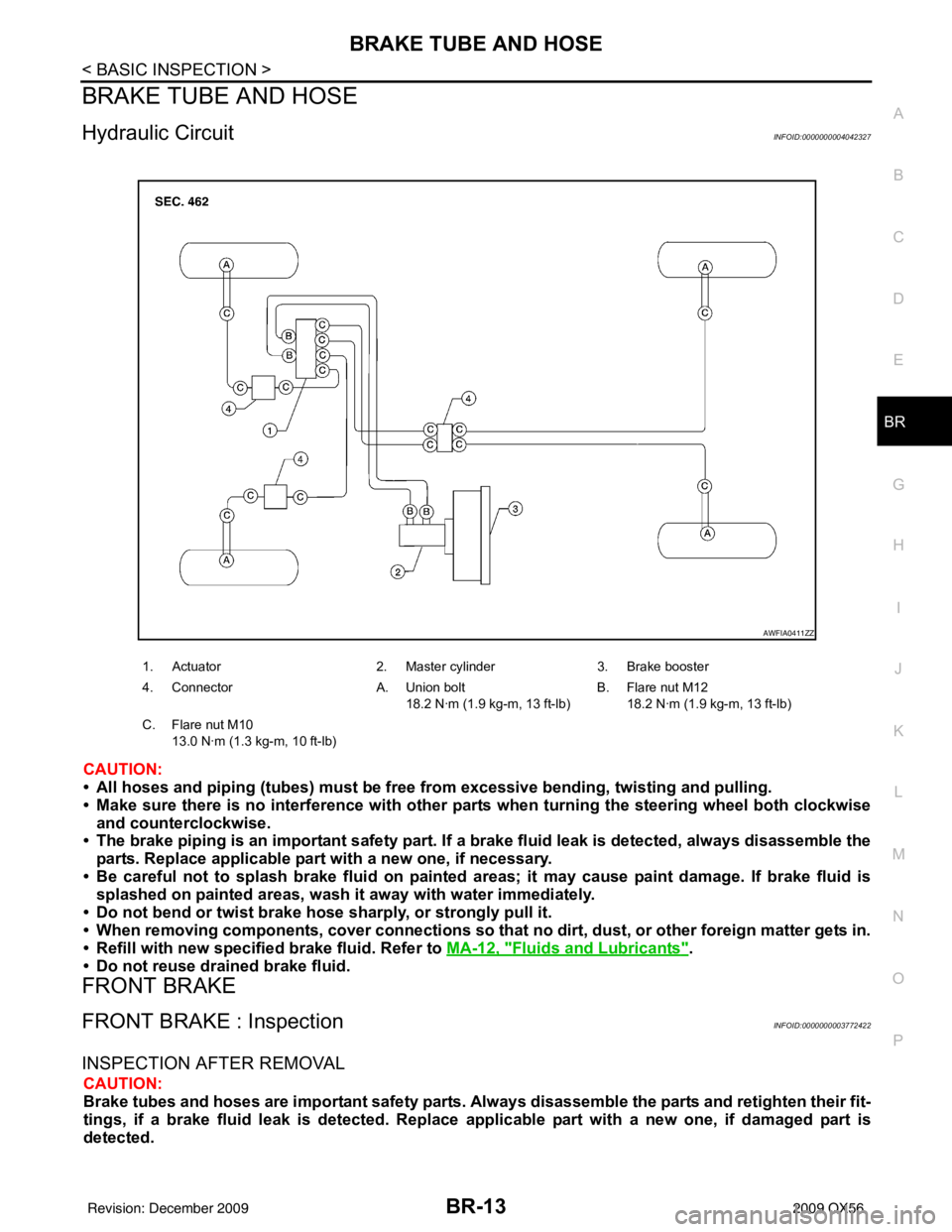
1. Actuator 2. Master cylinder3. Brake booster
4. Connector A. Union bolt
18.2 N·m (1.9 kg-m, 13 ft-lb) B. Flare nut M12
18.2 N·m (1.9 kg-m, 13 ft-lb)
C. Flare nut M10 13.0 N·m (1.3 kg-m, 10 ft-lb)
AWFIA0411ZZ
Revision: December 20092009 QX56
Page 444 of 4171

BR-14
< BASIC INSPECTION >
BRAKE TUBE AND HOSE
1. Check brake lines (tubes and hoses) and connections for fluid leaks, damage, twists, deformation, con-
tacts with other parts, and loose connections. Replace any parts as necessary. Refer to BR-21, "
Removal
and Installation of Front Brake Piping and Brake Hose".
2. While depressing brake pedal under a force of 785 N (80 kg-f, 177 lb-f) with engine running for approxi- mately 5 seconds, check each part for fluid leaks.
REAR BRAKE
REAR BRAKE : InspectionINFOID:0000000003772423
INSPECTION AFTER REMOVAL
CAUTION:
Brake tubes and hoses are important safety parts. Always disassemble the parts and retighten their fit-
tings, if a brake fluid leak is detected. Replace appl icable part with a new one, if damaged part is
detected.
1. Check brake lines (tubes and hoses) and connections fo r fluid leaks, damage, twists, deformation, con-
tacts with other parts, and loose connections. Replace any parts as necessary. Refer to BR-22, "
Removal
and Installation of Rear Brake Piping and Brake Hose".
2. While depressing brake pedal under a force of 785 N (80 kg-f, 177 lb-f) with engine running for approxi- mately 5 seconds, check each part for fluid leaks.
Revision: December 20092009 QX56
Page 447 of 4171

BRAKE FLUIDBR-17
< ON-VEHICLE MAINTENANCE >
C
DE
G H
I
J
K L
M A
B
BR
N
O P
BRAKE FLUID
On Board InspectionINFOID:0000000003772425
LEVEL CHECK
• Make sure the fluid level in reservoir tank is between MAX and MIN lines as shown.
• Visually check around reservoir tank for fluid leaks.
• If fluid level is excessively low, check brake system for leaks.
• If brake warning lamp remains illuminated after parking brake pedal is released, check brake system for fluid leaks.
Drain and RefillINFOID:0000000003772426
CAUTION:
• Refill with new brake fluid. Refer to MA-12, "
Fluids and Lubricants".
• Do not reuse drained brake fluid.
• Do not let brake fluid splash on the painted surfaces of the body. This might damage the paint, so if
splashing it, immediately wipe off the area and wash away with water.
• Before servicing, disconnect ABS actuator and electri c unit (control unit) connector or battery nega-
tive terminal.
1. Connect a vinyl tube to each bleed valve.
2. Depress brake pedal, loosen each bleed valve, and gradually remove brake fluid.
3. Make sure there is no foreign material in reservoir tank, and refill with new brake fluid.
4. Rest foot on brake pedal. Loosen bleed valve. Slowly depress pedal until it stops. Tighten bleed valve. Release brake pedal.
Repeat this process a few times, then pause to add new brake
fluid to master cylinder. Continue until new brake fluid flows out
of the bleed valve.
Bleed the air out of the brake hydraulic system. Refer to BR-17,
"Bleeding Brake System".
Bleeding Brake SystemINFOID:0000000003772427
CAUTION:
While bleeding, pay attention to master cylinder fluid level.
1. Turn ignition switch OFF and disconnect ABS actuator and electric unit (control unit) connector or battery
negative terminal.
2. Connect a vinyl tube to the rear right bleed valve.
LFIA0225E
SBR419C
SBR995
Revision: December 20092009 QX56
Page 448 of 4171
BR-18
< ON-VEHICLE MAINTENANCE >
BRAKE FLUID
3. Fully depress brake pedal 4 to 5 times.
4. With brake pedal depressed, loosen bleed valve to let the air out, and then tighten it immediately.
5. Repeat steps 3 and 4 until no more air comes out.
6. Tighten bleed valve to the specified torque. Refer to BR-31, "
Exploded View of Brake Caliper" (front disc
brake), BR-35, "
Exploded View of Brake Caliper" (rear disc brake).
7. Repeat steps 2 through 6 at each wheel, with master cylinder reservoir tank filled at least half way, bleed- ing air in order from the front left, rear left, and front right bleed valves.
Revision: December 20092009 QX56
Page 451 of 4171
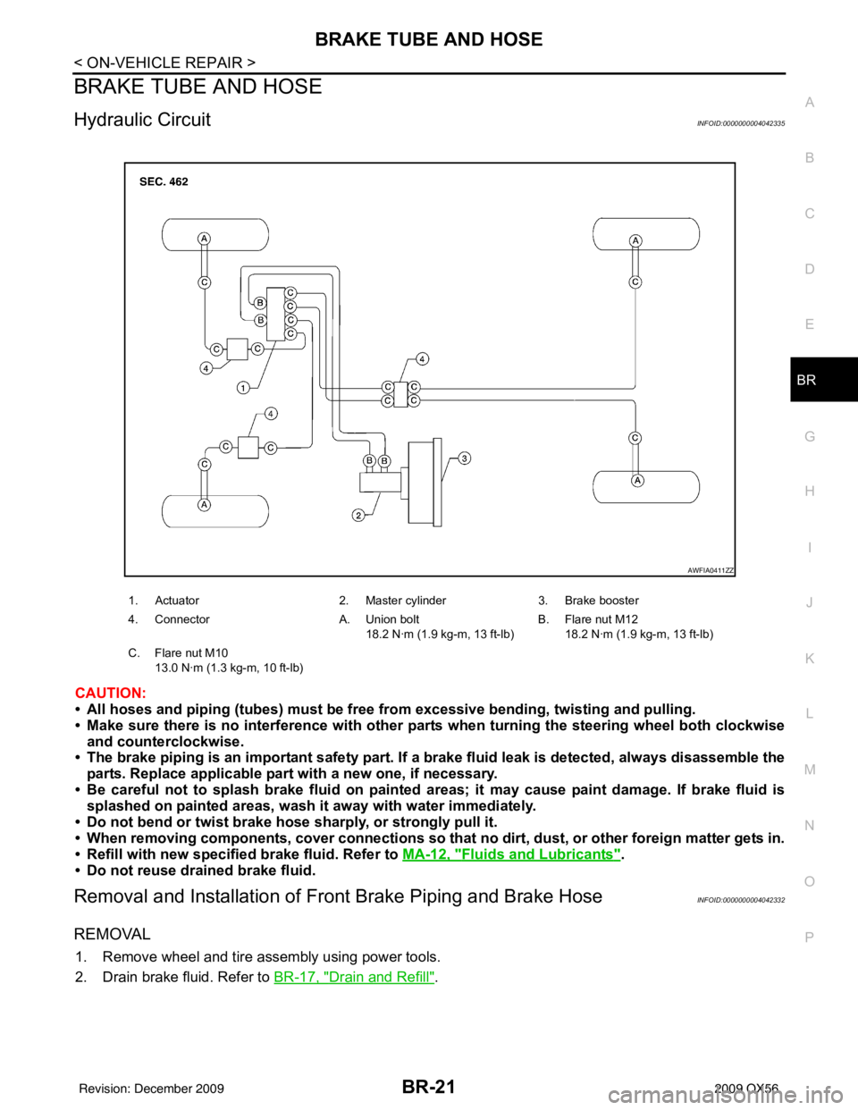
BRAKE TUBE AND HOSEBR-21
< ON-VEHICLE REPAIR >
C
DE
G H
I
J
K L
M A
B
BR
N
O P
BRAKE TUBE AND HOSE
Hydraulic CircuitINFOID:0000000004042335
CAUTION:
• All hoses and piping (tubes) must be fr ee from excessive bending, twisting and pulling.
• Make sure there is no interference with other parts when turning the steering wheel both clockwise
and counterclockwise.
• The brake piping is an important safety part. If a brake fluid leak is detected, always disassemble the
parts. Replace applicable part with a new one, if necessary.
• Be careful not to splash brake fluid on painted areas; it may cause paint damage. If brake fluid is
splashed on painted areas, wash it away with water immediately.
• Do not bend or twist brake hose sharply, or strongly pull it.
• When removing components, cover connections so that no dirt, dust, or other foreign matter gets in.
• Refill with new specified brake fluid. Refer to MA-12, "
Fluids and Lubricants".
• Do not reuse drained brake fluid.
Removal and Installation of Fr ont Brake Piping and Brake HoseINFOID:0000000004042332
REMOVAL
1. Remove wheel and tire assembly using power tools.
2. Drain brake fluid. Refer to BR-17, "
Drain and Refill".
1. Actuator 2. Master cylinder3. Brake booster
4. Connector A. Union bolt
18.2 N·m (1.9 kg-m, 13 ft-lb) B. Flare nut M12
18.2 N·m (1.9 kg-m, 13 ft-lb)
C. Flare nut M10 13.0 N·m (1.3 kg-m, 10 ft-lb)
AWFIA0411ZZ
Revision: December 20092009 QX56
Page 452 of 4171

BR-22
< ON-VEHICLE REPAIR >
BRAKE TUBE AND HOSE
3. Remove brake tube from brake hose, using a suitable tool.
4. Remove lock plate and brake hose from bracket.
5. Remove union bolt and then remove brake hose from cylinderbody.
INSTALLATION
1. Install brake hose by aligning with the protrusion on cylinderbody, then install the union bolt and new copper washers and
tighten to specification. Refer to BR-13, "
Hydraulic Circuit".
CAUTION:
Do not reuse copper washer.
2. Insert brake hose end through bracket, then secure it to bracket with lock plate.
3. Install brake tube to brake hose, then tighten the flare nut using a suitable tool. Refer to BR-13, "
Hydraulic Circuit".
4. Refill brake fluid and bleed air. Refer to BR-17, "
Drain and Refill".
5. Install wheel and tire assembly. Refer to WT-41, "
Adjustment".
Removal and Installation of Rear Brake Piping and Brake HoseINFOID:0000000004042333
REMOVAL
1. Remove wheel and tire assembly using power tools.
2. Drain brake fluid. Refer to BR-17, "
Drain and Refill".
LFIA0213E
LFIA0214E
SFIA1137E
LFIA0213E
Revision: December 20092009 QX56
Page 453 of 4171

BRAKE TUBE AND HOSEBR-23
< ON-VEHICLE REPAIR >
C
DE
G H
I
J
K L
M A
B
BR
N
O P
3. Remove brake tube from brake hose, using a suitable tool.
4. Remove lock plate and brake hose from bracket.
5. Remove union bolt and then remove brake hose from cylinder body.
INSTALLATION
1. Install brake hose by aligning with the protrusion on cylinderbody, then install the union bolt and new copper washers and
tighten to specification. Refer to BR-13, "
Hydraulic Circuit".
CAUTION:
Do not reuse copper washer.
2. Insert brake hose end through bracket, then secure it to bracket with lock plate.
3. Install brake tube to brake hose, then tighten the flare nut using a suitable tool. Refer to BR-13, "
Hydraulic Circuit".
4. Refill brake fluid and bleed air. Refer to BR-17, "
Bleeding Brake System".
5. Install wheel and tire assembly. Refer to WT-41, "
Adjustment"
Inspection After InstallationINFOID:0000000004042334
CAUTION:
Brake tubes and hoses are important safety parts. Always disassemble the parts and retighten their fit-
tings, if a brake fluid leak is detected. Replace applicable part with a new one, if a damaged part is
detected.
LFIA0213E
LFIA0212E
SFIA1137E
LFIA0213E
Revision: December 20092009 QX56