refrigerant type INFINITI QX56 2009 Factory Service Manual
[x] Cancel search | Manufacturer: INFINITI, Model Year: 2009, Model line: QX56, Model: INFINITI QX56 2009Pages: 4171, PDF Size: 84.65 MB
Page 2269 of 4171

PRECAUTIONSHA-5
< PRECAUTION >
C
DE
F
G H
J
K L
M A
B
HA
N
O P
General Refrigerant PrecautionINFOID:0000000003775289
WARNING:
Do not release refrigerant into the air. Use appr oved recovery/recycling equipment to capture the
refrigerant every time an air co nditioning system is discharged.
Always wear eye and hand protection (goggles and gloves) when working with any refrigerant or air
conditioning system.
Do not store or heat refrigerant containers above 52 °C (125 °F).
Do not heat a refrigerant containe r with an open flame; if container warming is required, place the
bottom of the container in a warm pail of water.
Do not intentionally drop, puncture, or incinerate refrigerant containers.
Keep refrigerant away from open flames: poison ous gas will be produced if refrigerant burns.
Refrigerant will displace oxygen, therefore be certa in to work in well ventilated areas to prevent suf-
focation.
Do not pressure test or leak test HFC-134a (R-134a) service equipment and/or vehicle air condition-
ing systems with compressed air during repair. Some mixtures of air and HFC-134a (R-134a) have
been shown to be combustible at elevated pressures. These mixtures, if ignited, may cause injury or
property damage. Additional health and safety info rmation may be obtained from refrigerant manu-
facturers.
Precaution for Leak Detection DyeINFOID:0000000003775290
The A/C system contains a fluorescent leak detection dy e used for locating refrigerant leaks. An ultraviolet
(UV) lamp is required to illuminate the dye when inspecting for leaks.
Always wear fluorescence enhancing UV safety goggles to protect your eyes and enhance the visibility of
the fluorescent dye.
The fluorescent dye leak detector is not a replacement for an electronic refrigerant leak detector. The fluo-
rescent dye leak detector should be used in conjuncti on with an electronic refrigerant leak detector (J-
41995).
For your safety and the customer's satisfaction, r ead and follow all manufacturer's operating instructions and
precautions prior to performing work.
A compressor shaft seal should not be repaired because of dye seepage. The compressor shaft seal should
only be repaired after confirming the leak with an electronic refrigerant leak detector (J-41995).
Always remove any dye from the leak area after repairs are complete to avoid a misdiagnosis during a future service.
Do not allow dye to come into contact with paint ed body panels or interior components. If dye is spilled,
clean immediately with the approved dye cleaner. Fluores cent dye left on a surface for an extended period of
time cannot be removed .
Do not spray the fluorescent dye cleaning agent on hot surfaces (engine exhaust manifold, etc.).
Do not use more than one refrigerant dye bot tle (1/4 ounce / 7.4 cc) per A/C system.
Leak detection dyes for HFC-134a (R-134a) and CFC-12 (R -12) A/C systems are different. Do not use HFC-
134a (R-134a) leak detection dye in CFC-12 (R-12) A/ C systems or CFC-12 (R-12) leak detection dye in
HFC-134a (R-134a) A/C systems or A/C system damage may result.
The fluorescent properties of the dye will remain for over three (3) years unless a compressor failure occurs.
A/C Identification LabelINFOID:0000000003775291
Vehicles with factory installed fluorescent dye have this identification label on the underside of hood.
Precaution for Refrigerant ConnectionINFOID:0000000003775292
A new type refrigerant connection has been introduced to all refrigerant lines except the following locations.
Expansion valve to cooling unit
Evaporator pipes to evaporator (inside cooling unit)
Refrigerant pressure sensor
FEATURES OF NEW TYPE REFRIGERANT CONNECTION
The O-ring has been relocated. It has also been provided with a groove for proper installation. This reduces the possibility of the O-ring being caught in, or damaged by , the mating part. The sealing direction of the O-
ring is now set vertically in relation to the contacting surface of the mating part to improve sealing character-
istics.
Revision: December 20092009 QX56
Page 2273 of 4171

PRECAUTIONSHA-9
< PRECAUTION >
C
DE
F
G H
J
K L
M A
B
HA
N
O P
*: Always check with the Parts Department for the latest parts information.
WARNING:
Make sure all refrigerant is discharged into the recycling equipment and the pressure in the system is
less than atmospheric pressure. Then gradually loo sen the discharge side hose fitting and remove it.
CAUTION:
When replacing or cleaning refrigerant cycle components, observe the following.
When the compressor is removed, st ore it in the same position as it is when mounted on the car.
Failure to do so will cause oil to enter the low pressure chamber.
When connecting tubes, always use a to rque wrench and a back-up wrench.
After disconnecting tubes, immediately plug all op enings to prevent entry of dirt and moisture.
When installing an air conditioner in the vehicle, connect the pipes as the final stage of the opera-
tion. Do not remove the seal caps of pipes and other components until just before required for con-
nection.
Allow components stored in cool areas to warm to working area temperature before removing seal
caps. This prevents condensation from forming inside A/C components.
Thoroughly remove moisture from the refriger ation system before charging the refrigerant.
Always replace used O-rings.
When connecting tube, apply oil to circle of the O-ri ngs shown in illustration. Be careful not to apply
oil to threaded portion.
Oil name: NISSAN A/C System Oil Type S or equivalent
O-ring must be closely attached to dented portion of tube.
When replacing the O-ring, be careful not to damage O-ring and tube.
Connect tube until you hear it cl ick, then tighten the nut or bolt by hand until snug. Make sure that
the O-ring is installed to tube correctly.
After connecting line, conduct leak test and make sure that there is no leakage from connections.
When the gas leaking point is f ound, disconnect that line and replace the O-ring. Then tighten con-
nections of seal seat to the specified torque.
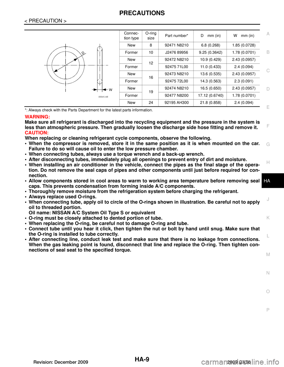
Connec-
tion type O-ring
size Part number* D mm (in) W mm (in)
New 8 92471 N8210 6.8 (0.268) 1.85 (0.0728)
Former 10 J2476 89956 9.25 (0.3642) 1.78 (0.0701) New 1292472 N8210 10.9 (0.429) 2.43 (0.0957)
Former 92475 71L00 11.0 (0.433) 2.4 (0.094) New 1692473 N8210 13.6 (0.535) 2.43 (0.0957)
Former 92475 72L00 14.3 (0.563) 2.3 (0.091) New 1992474 N8210 16.5 (0.650) 2.43 (0.0957)
Former 92477 N8200 17.12 (0.6740) 1.78 (0.0701) New 24 92195 AH300 21.8 (0.858) 2.4 (0.094)
SHA814E
Revision: December 20092009 QX56
Page 2277 of 4171

PREPARATIONHA-13
< PREPARATION >
C
DE
F
G H
J
K L
M A
B
HA
N
O P
PREPARATION
PREPARATION
Special Service ToolINFOID:0000000003775295
The actual shapes of Kent-Moore tools may differ fr om those of special service tools illustrated here.
HFC-134a (R-134a) Service Tool and EquipmentINFOID:0000000003775296
Never mix HFC-134a (R-134a) refrigerant and/or the spec ified oil with CFC-12 (R-12) refrigerant and/or the
oil.
Separate and non-interchangeable service equipment must be used for handling each type of refrigerant/oil.
Refrigerant container fittings, service hose fittings and service equipment fittings (equipment which handles
refrigerant and/or oil) are different between CFC-12 (R-12) and HFC-134a (R-134a). This is to avoid mixed
use of the refrigerants/oil.
Adapters that convert one size fitti ng to another must never be used refrigerant/oil contamination will occur
and compressor failure will result.
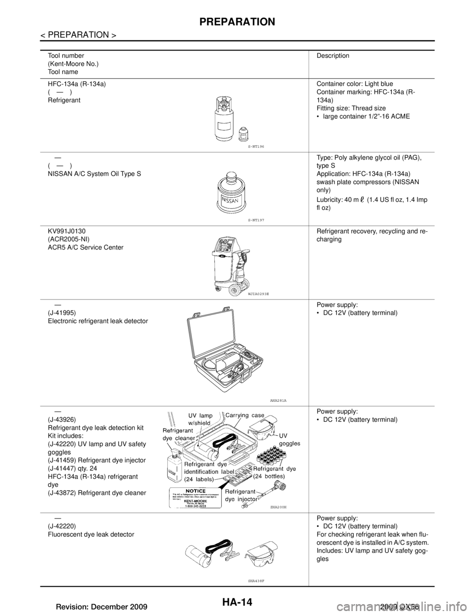
Tool number
(Kent-Moore No.)
Tool name Description
—
(J-41425-NIS)
Aluminum tube repair kit Repairing leaks in A/C tubes
—
(J-38873-A)
Pulley installer Installing pulley
—
(J-44614)
Clutch disc holding tool Clutch disc holding tool
ALIIA0390ZZ
LHA171
WHA230
Revision: December 20092009 QX56
Page 2278 of 4171

HA-14
< PREPARATION >
PREPARATION
Tool number
(Kent-Moore No.)
Tool nameDescription
HFC-134a (R-134a)
(—)
Refrigerant Container color: Light blue
Container marking: HFC-134a (R-
134a)
Fitting size: Thread size
large container 1/2”-16 ACME
—
(—)
NISSAN A/C System Oil Type S Type: Poly alkylene glycol oil (PAG),
type S
Application: HFC-134a (R-134a)
swash plate compressors (NISSAN
only)
Lubricity: 40 m (1.4 US fl oz, 1.4 Imp
fl oz)
KV991J0130
(ACR2005-NI)
ACR5 A/C Service Center Refrigerant recovery, recycling and re-
charging
—
(J-41995)
Electronic refrigerant leak detector Power supply:
DC 12V (batte
ry terminal)
—
(J-43926)
Refrigerant dye leak detection kit
Kit includes:
(J-42220) UV lamp and UV safety
goggles
(J-41459) Refrigerant dye injector
(J-41447) qty. 24
HFC-134a (R-134a) refrigerant
dye
(J-43872) Refrigerant dye cleaner Power supply:
DC 12V (batte
ry terminal)
—
(J-42220)
Fluorescent dye leak detector Power supply:
DC 12V (batte
ry terminal)
For checking refrigerant leak when flu-
orescent dye is installed in A/C system.
Includes: UV lamp and UV safety gog-
gles
S-NT196
S-NT197
WJIA0293E
AHA281A
ZHA200H
SHA438F
Revision: December 20092009 QX56
Page 2286 of 4171

HA-22
< ON-VEHICLE MAINTENANCE >
OIL
OIL
Maintenance of Oil Quantity in CompressorINFOID:0000000003775302
The oil in the compressor circulates through the system with the refrigerant. Add oil to compressor when
replacing any component or after a large refrigerant leakage has occurred. It is important to maintain the spec-
ified amount.
If oil quantity is not maintained properly, the following malfunctions may result:
Lack of oil: May lead to a seized compressor
Excessive oil: Inadequate cooling (thermal exchange interference)
OIL
Name: NISSAN A/C System Oil Type S or equivalent
CHECKING AND ADJUSTING
CAUTION:
If excessive oil leakage is noted, do no t perform the oil return operation.
Start the engine and set the following conditions:
Test Condition
Engine speed: Idling to 1,200 rpm
A/C switch: On
Blower fan speed: MAX position
Temp. control: Optional [Set so that intake air temperature is 25 ° to 30 ° C (77 ° to 86 °F)]
Intake position: Recirculation ( )
Perform oil return operation for about ten minutes
Adjust the oil quantity according to the following table.
Oil Adjusting Procedure for Components Replacement Except Compressor
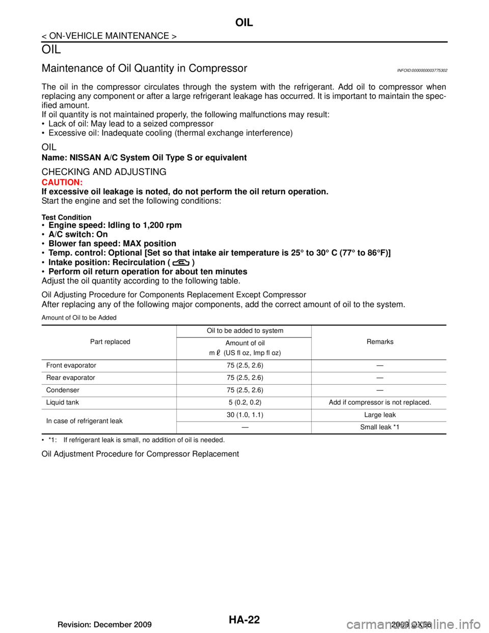
After replacing any of the following major component s, add the correct amount of oil to the system.
Amount of Oil to be Added
*1: If refrigerant leak is small, no addition of oil is needed.
Oil Adjustment Procedure for Compressor Replacement
Part replacedOil to be added to system
Remarks
Amount of oil
m (US fl oz, Imp fl oz)
Front evaporator 75 (2.5, 2.6) —
Rear evaporator 75 (2.5, 2.6) —
Condenser 75 (2.5, 2.6) —
Liquid tank 5 (0.2, 0.2) Add if compressor is not replaced.
In case of refrigerant leak 30 (1.0, 1.1) Large leak
— Small leak *1
Revision: December 20092009 QX56
Page 2313 of 4171

SERVICE DATA AND SPECIFICATIONS (SDS)
HA-49
< SERVICE DATA AND SPECIFICATIONS (SDS)
C
D E
F
G H
J
K L
M A
B
HA
N
O P
SERVICE DATA AND SPECIFICATIONS (SDS)
SERVICE DATA AND SPECIFICATIONS (SDS)
Service Data and Specification (SDS)INFOID:0000000003775323
COMPRESSOR
OIL
REFRIGERANT
Make ZEXEL VALEO CLIMATE CONTROL
Model DKS-17D
Typ e Swash plate
Displacement 175.5 cm
3 (10.7 in3 ) / revolution
Cylinder bore × stroke 30.5 mm (1.20 in) x 24.0 mm (0.94 in)
Direction of rotation Clockwise (viewed from drive end)
Drive belt Poly V
Name NISSAN A/C System Oil Type S
Capacity 290 m (9.8 US fl oz, 10.2 Imp fl oz)
Typ eHFC 134a (R-134a)
Capacity 1.08 ± 0.05 kg (2.38 ± 0.11 lb)
Revision: December 20092009 QX56
Page 2436 of 4171
![INFINITI QX56 2009 Factory Service Manual PRECAUTIONSHAC-123
< PRECAUTION > [AUTOMATIC AIR CONDITIONER]
C
D
E
F
G H
J
K L
M A
B
HAC
N
O P
PRECAUTION
PRECAUTIONS
Precaution for Supplemental Restraint System (SRS) "AIR BAG" and "SEAT BELT
PRE INFINITI QX56 2009 Factory Service Manual PRECAUTIONSHAC-123
< PRECAUTION > [AUTOMATIC AIR CONDITIONER]
C
D
E
F
G H
J
K L
M A
B
HAC
N
O P
PRECAUTION
PRECAUTIONS
Precaution for Supplemental Restraint System (SRS) "AIR BAG" and "SEAT BELT
PRE](/img/42/57031/w960_57031-2435.png)
PRECAUTIONSHAC-123
< PRECAUTION > [AUTOMATIC AIR CONDITIONER]
C
D
E
F
G H
J
K L
M A
B
HAC
N
O P
PRECAUTION
PRECAUTIONS
Precaution for Supplemental Restraint System (SRS) "AIR BAG" and "SEAT BELT
PRE-TENSIONER"
INFOID:0000000005867494
The Supplemental Restraint System such as “AIR BAG” and “SEAT BELT PRE-TENSIONER”, used along
with a front seat belt, helps to reduce the risk or severi ty of injury to the driver and front passenger for certain
types of collision. This system includes seat belt switch inputs and dual stage front air bag modules. The SRS
system uses the seat belt switches to determine the front air bag deployment, and may only deploy one front
air bag, depending on the severity of a collision and w hether the front occupants are belted or unbelted.
Information necessary to service the system safely is included in the SR and SB section of this Service Man-
ual.
WARNING:
• To avoid rendering the SRS inoper ative, which could increase the risk of personal injury or death in
the event of a collision which would result in air bag inflation, all maintenance must be performed by
an authorized NISSAN/INFINITI dealer.
• Improper maintenance, including in correct removal and installation of the SRS, can lead to personal
injury caused by unintentional act ivation of the system. For removal of Spiral Cable and Air Bag
Module, see the SR section.
• Do not use electrical test equipm ent on any circuit related to the SRS unless instructed to in this
Service Manual. SRS wiring harnesses can be identi fied by yellow and/or orange harnesses or har-
ness connectors.
PRECAUTIONS WHEN USING POWER TOOLS (AIR OR ELECTRIC) AND HAMMERS
WARNING:
• When working near the Airbag Diagnosis Sensor Un it or other Airbag System sensors with the Igni-
tion ON or engine running, DO NOT use air or el ectric power tools or strike near the sensor(s) with a
hammer. Heavy vibration could activate the sensor( s) and deploy the air bag(s), possibly causing
serious injury.
• When using air or electric power tools or hammers, always switch the Ignition OFF, disconnect the battery, and wait at least 3 minutes before performing any service.
Working with HFC-134a (R-134a)INFOID:0000000003775400
WARNING:
• CFC-12 (R-12) refrigerant and HFC-134a (R-134a) refr igerant are not compatible. If the refrigerants
are mixed compressor failure is likely to occur. Refer to HA-4, "
Contaminated Refrigerant". To deter-
mine the purity of HFC-134a (R-134a) in the vehic le and recovery tank, use Refrigerant Recovery/
Recycling Recharging equipment and Refrigerant Identifier.
• Use only specified oil for the HFC-134a (R-134a) A/C system and HFC-134a (R-134a) components. If oil other than that specified is used, compressor fa ilure is likely to occur.
• The specified HFC-134a (R-134a) oil rapidly absorb s moisture from the atmosphere. The following
handling precautions must be observed:
- When removing refrigerant components from a vehicle, immediately cap (seal) the component to
minimize the entry of mois ture from the atmosphere.
- When installing refrigerant components to a vehicle, do not remove the caps (unseal) until just
before connecting the co mponents. Connect all refrigerant lo op components as quickly as possible
to minimize the entry of moisture into system.
- Only use the specified oil from a sealed container. Immediately r eseal containers of oil. Without
proper sealing, oil will become moisture saturat ed and should not be used.
- Avoid breathing A/C refrigerant and oil vapor or mist. Exposure may irritate eyes, nose and throat.
Remove HFC-134a (R-134a) from the A/C system usi ng certified service equipment meeting require-
ments of SAE J2210 [HFC-134a (R-134a) recycling equipment], or J2209 [HFC-134a (R-134a) recy-
cling equipment], If accidental system discharge occurs, ventilate work area before resuming
service. Additional health and safety information may be obtained from refrigerant and oil manufac-
turers.
- Do not allow A/C oil to come in contact with styrofoam parts. Damage may result.
CONTAMINATED REFRIGERANT
Revision: December 20092009 QX56
Page 2685 of 4171

MA-12
< ON-VEHICLE MAINTENANCE >
RECOMMENDED FLUIDS AND LUBRICANTS
RECOMMENDED FLUIDS AND LUBRICANTS
Fluids and LubricantsINFOID:0000000003776984
*1: For further details, refer to MA-13, "Engine Oil Recommendation".
*2: If Genuine NISSAN Matic S ATF is not available, Genuine Matic J ATF may also be used. Using automatic transmission fluid
other than Genuine NISSAN Matic S ATF or Matic J ATF will cause deterioration in drivability and automatic transmission dura-
bility, and may damage the automatic transmission, which is not covered by the INFINITI new vehicle limited warranty.
*3: DEXRON
TM VI type ATF may also be used.
*4: Available in mainland U.S.A. through an INFINITI dealer.
*5: For further details, see “Air conditioner specification label”.
*6: For hot climates, viscosity SAE 90 is suitable for ambient te mperatures above 0° C (32 ° F).
*7: For improved vehicle performance, INFINITI recommends the use of unleaded premium gasoline with an octane rating of at leas t 91
AKI (RON 96). For further details, refer to GI-27, "
Precaution for Fuel (Unleaded Premium Gasoline Recommended)",
*8: See an INFINITI dealer for service for synthetic oil.
*9: Using fluid other than Genuine Nissan Matic D ATF may cause deterioration in drivability and transfer durability, and may d amage the
transfer, which is not covered by the (INFINITI new vehicle limited) warranty. Description
Capacity (Approximate)
Recommended Fluids/Lubricants
Metric US measure Imp measure
Fuel 105.8 28 gal 23 1/4 gal Unleaded gasoline with octane rating of
at least 87 AKI (RON 91) *7
Engine oil
Drain and refill With oil filter
change
6.5
6 7/8 qt 5 3/4 qt
• Engine oil with API Certification Mark*1
• Viscosity SAE 5W-30
Without oil filter
change
6.2
6 1/2 qt 5 1/2 qt
Dry engine (engine overhaul) 7.6 8 qt
6 3/4 qt
Cooling system With reservoir
at MAX level
14.4
15 1/4 qt 12 5/8 qt Genuine NISSAN Long Life Anti-freeze
coolant or equivalent
Automatic transmission fluid (ATF) 10.6 11 1/4 qt 9 3/8 qt Genuine NISSAN Matic S ATF *2
Rear differential gear oil 1.75 3 3/4 pt 3 1/8 pt API GL-5 Synthetic 75W-90 Gear Oil
(Part No. 999MP-DF200P) or equivalent
*8
Transfer fluid 3.0 3 1/8 qt 2 5/8 qt Genuine NISSAN Matic D ATF recom-
mended *9
Front differential gear oil 1.6 3 3/8 pt 2 7/8 pt Genuine NISSAN Differential Oil Hypoid
Super GL-5 80W-90 or API GL-5 Viscosi-
ty SAE 80W-90*6
Power steering fluid (PSF) 1.0 1 1/8 qt 7/8 qt Genuine NISSAN PSF or equivalent *3
Brake fluid —— —Genuine NISSAN Super Heavy Duty
Brake Fluid or equivalent,
DOT 3 (US FMVSS No. 116) *4
Brake grease —— —PBC (poly butyl cuprysil) grease or equiv-
alent
Multi-purpose grease —— — NLGI No. 2 (lithium soap base)
Windshield washer fluid 4.5 4 3/4 qt
4 qtGenuine NISSAN Windshield Washer
Concentrate Cleaner & Anti-freeze or
equivalent
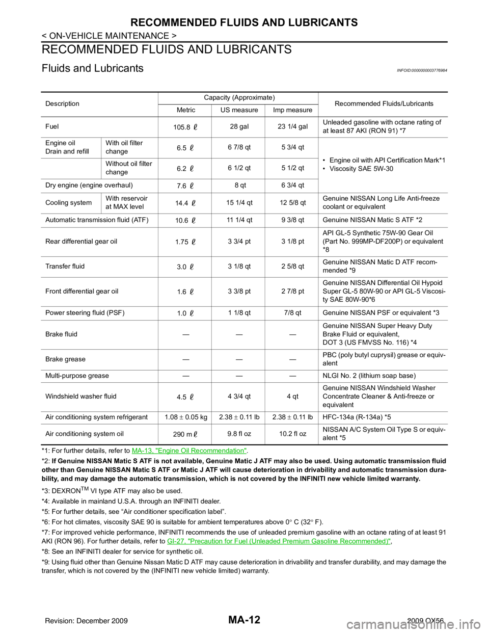
Air conditioning system refrigerant 1.08 ± 0.05 kg 2.38 ± 0.11 lb 2.38 ± 0.11 lb HFC-134a (R-134a) *5
Air conditioning system oil 290 m9.8 fl oz 10.2 fl oz NISSAN A/C System Oil Type S or equiv-
alent *5
Revision: December 20092009 QX56