power steering fluid INFINITI QX56 2010 Factory User Guide
[x] Cancel search | Manufacturer: INFINITI, Model Year: 2010, Model line: QX56, Model: INFINITI QX56 2010Pages: 4210, PDF Size: 81.91 MB
Page 2711 of 4210
GENERAL MAINTENANCEMA-7
< ON-VEHICLE MAINTENANCE >
C
DE
F
G H
I
J
K L
M B
MA
N
O A
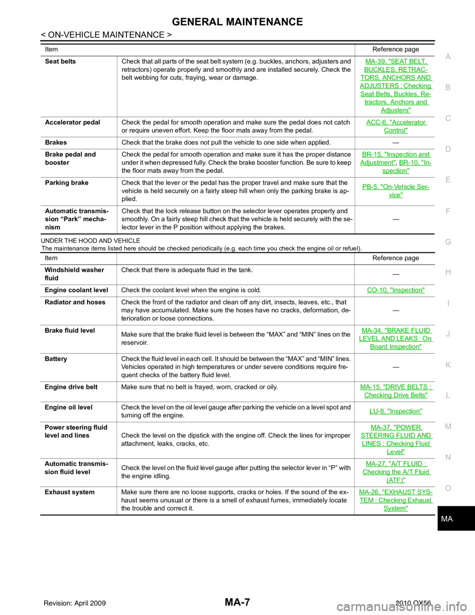
UNDER THE HOOD AND VEHICLE
The maintenance items listed here should be checked periodically (e.g. each time you check the engine oil or refuel).
Seat beltsCheck that all parts of the seat belt system (e.g. buckles, anchors, adjusters and
retractors) operate properly and smoothly and are installed securely. Check the
belt webbing for cuts, fraying, wear or damage. MA-39, "SEAT BELT,
BUCKLES, RETRAC-
TORS, ANCHORS AND
ADJUSTERS : Checking
Seat Belts, Buckles, Re-
tractors, Anchors and
Adjusters"
Accelerator pedal
Check the pedal for smooth operation and make sure the pedal does not catch
or require uneven effort. Keep the floor mats away from the pedal. ACC-6, "Accelerator
Control"
Brakes
Check that the brake does not pull the vehicle to one side when applied. —
Brake pedal and
booster Check the pedal for smooth operation and make sure it has the proper distance
under it when depressed fully. Check the brake booster function. Be sure to keep
the floor mats away from the pedal. BR-15, "
Inspection and
Adjustment", BR-10, "In-
spection"
Parking brake
Check that the lever or the pedal has the proper travel and make sure that the
vehicle is held securely on a fairly steep hill when only the parking brake is ap-
plied. PB-5, "On-Vehicle Ser-
vice"
Automatic transmis-
sion “Park” mecha-
nismCheck that the lock release button on the selector lever operates properly and
smoothly. On a fairly steep hill check that the vehicle is held securely with the se-
lector lever in the P position without applying the brakes.
—
Item
Reference page
Item Reference page
Windshield washer
fluid Check that there is adequate fluid in the tank.
—
Engine coolant level Check the coolant level when the engine is cold. CO-10, "
Inspection"
Radiator and hosesCheck the front of the radiator and clean off any dirt, insects, leaves, etc., that
may have accumulated. Make sure the hoses have no cracks, deformation, de-
terioration or loose connections. —
Brake fluid level Make sure that the brake fluid level is between the “MAX” and “MIN” lines on the
reservoir. MA-34, "
BRAKE FLUID
LEVEL AND LEAKS : On
Board Inspection"
Battery
Check the fluid level in each cell. It should be between the “MAX” and “MIN” lines.
Vehicles operated in high temperatures or under severe conditions require fre-
quent checks of the battery fluid level. —
Engine drive belt Make sure that no belt is frayed, worn, cracked or oily. MA-15, "
DRIVE BELTS :
Checking Drive Belts"
Engine oil levelCheck the level on the oil level gauge after parking the vehicle on a level spot and
turning off the engine. LU-8, "Inspection"
Power steering fluid
level and lines
Check the level on the dipstick with the engine off. Check the lines for improper
attachment, leaks, cracks, etc. MA-37, "POWER
STEERING FLUID AND
LINES : Checking Fluid
Level"
Automatic transmis-
sion fluid level
Check the level on the fluid level gauge after putting the selector lever in “P” with
the engine idling. MA-27, "A/T FLUID :
Checking the A/T Fluid
(ATF)"
Exhaust system
Make sure there are no loose supports, cracks or holes. If the sound of the ex-
haust seems unusual or there is a smell of exhaust fumes, immediately locate
the trouble and correct it. MA-26, "EXHAUST SYS-
TEM : Checking Exhaust
System"
Revision: April 20092010 QX56
Page 2717 of 4210
RECOMMENDED FLUIDS AND LUBRICANTSMA-13
< ON-VEHICLE MAINTENANCE >
C
DE
F
G H
I
J
K L
M B
MA
N
O A
RECOMMENDED FLUIDS AND LUBRICANTS
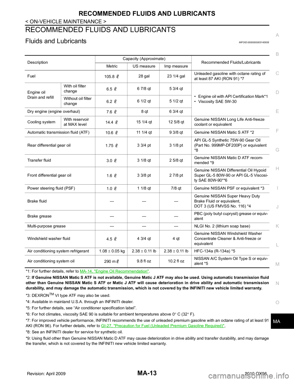
Fluids and LubricantsINFOID:0000000005145938
*1: For further details, refer to
MA-14, "Engine Oil Recommendation".
*2: If Genuine NISSAN Matic S ATF is not ava ilable, Genuine Matic J ATF may also be used. Using automatic transmission fluid
other than Genuine NISSAN Matic S ATF or Matic J ATF will cause deterioration in drive ability and automatic transmission
durability, and may damage the automatic transmission, which is not covered by the INFINITI new vehicle limited warranty.
*3: DEXRON
TM VI type ATF may also be used.
*4: Available in mainland U.S.A. through an INFINITI dealer.
*5: For further details, see “Air conditioner specification label”.
*6: For hot climates, viscosity SAE 90 is suitable for ambient temperatures above 0° C (32° F).
*7: For improved vehicle performance, INFINITI recommends the use of unleaded premium gasoline with an octane rating of at leas t 91
AKI (RON 96). For furt her details, refer to GI-27, "
Precaution for Fuel (Unleaded Premium Gasoline Required)",
*8: See an INFINITI dealer for service for synthetic oil.
*9: Using fluid other than Genuin e NISSAN Matic D ATF may cause deterioration in drive ability and transfer durability, and may damage
the transfer, which is not covered by the INFINITI new vehicle limited warranty. Description
Capacity (Approximate)
Recommended Fluids/Lubricants
Metric US measure Imp measure
Fuel 105.8 28 gal 23 1/4 gal Unleaded gasoline with octane rating of
at least 87 AKI (RON 91) *7
Engine oil
Drain and refill With oil filter
change
6.5
6 7/8 qt 5 3/4 qt
• Engine oil with API Certification Mark*1
• Viscosity SAE 5W-30
Without oil filter
change
6.2
6 1/2 qt 5 1/2 qt
Dry engine (engine overhaul) 7.6 8 qt
6 3/4 qt
Cooling system With reservoir
at MAX level
14.4
15 1/4 qt 12 5/8 qt Genuine NISSAN Long
Life Anti-freeze
coolant or equivalent
Automatic transmission fluid (ATF) 10.6 11 1/4 qt 9 3/8 qt Genuine NISSAN Matic S ATF *2
Rear differential gear oil 1.75 3 3/4 pt 3 1/8 pt API GL-5 Synthetic 75W-90 Gear Oil
(Part No. 999MP-DF200P) or equivalent
*8
Transfer fluid 3.0 3 1/8 qt 2 5/8 qt Genuine NISSAN Matic D ATF recom-
mended *9
Front differential gear oil 1.6 3 3/8 pt 2 7/8 pt Genuine NISSAN Differ
ential Oil Hypoid
Super GL-5 80W-90 or API GL-5 Viscosi-
ty SAE 80W-90**6
Power steering fluid (PSF) 1.0 1 1/8 qt 7/8 qt Genuine NISSAN PSF or equivalent *3
Brake fluid ———Genuine NISSAN S
uper Heavy Duty
Brake Fluid or equivalent,
DOT 3 (US FMVSS No. 116) *4
Brake grease ———PBC (poly butyl cuprysil) grease or equiv-
alent
Multi-purpose grease ——— NLGI No. 2 (lithium soap base)
Windshield washer fluid 4.5 4 3/4 qt
4 qtGenuine NISSAN Wind
shield Washer
Concentrate Cleaner & Anti-freeze or
equivalent
Air conditioning system refrigerant 1.08 ± 0.05 kg 2.38 ± 0.11 lb 2.38 ± 0.11 lb HFC-134a (R-134a) *5
Air conditioning system oil 290 m9.8 fl oz 10.2 fl oz NISSAN A/C System Oil Type S or equiv-
alent *5
Revision: April 20092010 QX56
Page 2741 of 4210
CHASSIS AND BODY MAINTENANCEMA-37
< ON-VEHICLE MAINTENANCE >
C
DE
F
G H
I
J
K L
M B
MA
N
O A
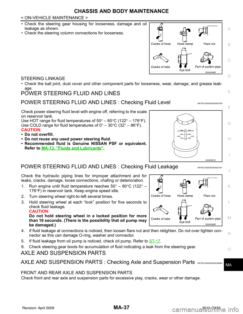
• Check the steering gear housing for looseness, damage and oil
leakage as shown.
• Check the steering column connections for looseness.
STEERING LINKAGE
• Check the ball joint, dust cover and other component parts for looseness, wear, damage, and grease leak-
age.
POWER STEERING FLUID AND LINES
POWER STEERING FLUID AND LINE S : Checking Fluid LevelINFOID:0000000005403166
Check power steering fluid level with engine off, referring to the scale
on reservoir tank.
Use HOT range for fluid temperatures of 50 ° – 80 °C (122 ° – 176 °F).
Use COLD range for fluid temperatures of 0 ° – 30 °C (32° – 86°F).
CAUTION:
• Do not overfill.
• Do not reuse any used power steering fluid.
• Recommended fluid is Genuine NISSAN PSF or equivalent.
Refer to MA-13, "
Fluids and Lubricants".
POWER STEERING FLUID AND LINES : Checking Fluid LeakageINFOID:0000000005403167
Check the hydraulic piping lines for improper attachment and for
leaks, cracks, damage, loose connec tions, chafing or deterioration.
1. Run engine until fluid temperature reaches 50 ° – 80° C (122° –
176° F) in reservoir tank. Keep engine speed idle.
2. Turn steering wheel right-to-left several times.
3. Hold steering wheel at each “lock” position for five seconds to check fluid leakage.
CAUTION:
Do not hold steering wheel in a locked position for more
than 10 seconds. (There is the possibility that oil pump may
be damaged.)
4. If fluid leakage at connections is noticed, then loosen flare nut and then retighten. Do not over tighten con- nector as this can damage O-ring, washer and connector.
5. If fluid leakage from oil pump is noticed, check oil pump. Refer to ST-17
.
6. Check steering gear boots for accumulation of fluid indicating a leak from the steering gear.
AXLE AND SUSPENSION PARTS
AXLE AND SUSPENSION PARTS : Chec king Axle and Suspension PartsINFOID:0000000005259684
FRONT AND REAR AXLE AND SUSPENSION PARTS
Check front and rear axle and suspension parts for excessive play, cracks, wear or other damage.
SGIA0506E
LGIA0021E
SGIA0506E
Revision: April 20092010 QX56
Page 3639 of 4210

ST-1
STEERING
C
DE
F
H I
J
K L
M
SECTION ST
A
B
ST
N
O P
CONTENTS
STEERING SYSTEM
PRECAUTION ....... ........................................3
PRECAUTIONS .............................................. .....3
Precaution for Supplemental Restraint System
(SRS) "AIR BAG" and "SEAT BELT PRE-TEN-
SIONER" ............................................................. ......
3
Precaution Necessary for Steering Wheel Rota-
tion After Battery Disconnect ............................... ......
3
PREPARATION ............................................5
PREPARATION .............................................. .....5
Special Service Tool ........................................... ......5
Commercial Service Tool ..........................................6
FUNCTION DIAGNOSIS ...............................7
HEATED STEERING WHEEL ........................ .....7
System Diagram .................................................. ......7
System Description ...................................................7
Component Parts Location ........................................7
Component Description .............................................8
COMPONENT DIAGNOSIS ..........................9
HEATED STEERING WHEEL ........................ .....9
Wiring Diagram ................................................... ......9
SYMPTOM DIAGNOSIS ..............................12
NOISE, VIBRATION AND HARSHNESS
(NVH) TROUBLESHOOTING ........................ ....
12
NVH Troubleshooting Chart ................................ ....12
ON-VEHICLE MAINTENANCE ....................13
POWER STEERING FLUID ........................... ....13
Checking Fluid Level ........................................... ....13
Checking Fluid Leakage ..........................................13
Air Bleeding Hydraulic System ................................13
ON-VEHICLE REPAIR .................................15
STEERING WHEEL ..........................................15
On-Vehicle Inspection and Service ..................... ....15
POWER STEERING OIL PUMP .......................17
On-Vehicle Inspection and Service .........................17
REMOVAL AND INSTALLATION ...............18
STEERING WHEEL ..........................................18
Removal and Installation ..................................... ....18
TILT SYSTEM ...................................................19
Removal and Installation .........................................19
STEERING COLUMN ........................................20
Removal and Installation .........................................20
POWER STEERING GEAR AND LINKAGE ....23
Removal and Installation .........................................23
POWER STEERING OIL PUMP .......................26
Removal and Installation .........................................26
HYDRAULIC LINE ............................................27
Removal and Installation .........................................27
DISASSEMBLY AND ASSEMBLY ..............29
STEERING COLUMN ........................................29
Disassembly and Assembly ................................. ....29
POWER STEERING GEAR AND LINKAGE ....31
Disassembly and Assembly .....................................31
POWER STEERING OIL PUMP .......................34
Disassembly and Assembly .....................................34
SERVICE DATA AND SPECIFICATIONS
(SDS) ............... .......................................... ...
35
SERVICE DATA AND SPECIFICATIONS
(SDS) .................................................................
35
Steering Wheel .................................................... ....35
Revision: April 20092010 QX56
Page 3651 of 4210
POWER STEERING FLUIDST-13
< ON-VEHICLE MAINTENANCE >
C
DE
F
H I
J
K L
M A
B
ST
N
O P
ON-VEHICLE MAINTENANCE
POWER STEERING FLUID
Checking Fluid LevelINFOID:0000000005147865
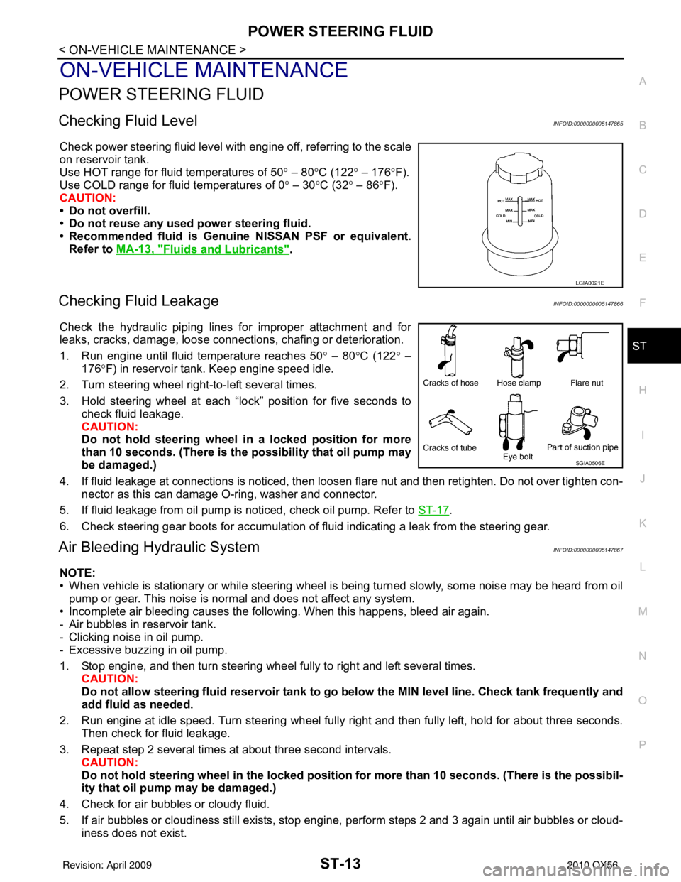
Check power steering fluid level with engine off, referring to the scale
on reservoir tank.
Use HOT range for fluid temperatures of 50 ° – 80 °C (122 ° – 176 °F).
Use COLD range for fluid temperatures of 0 ° – 30 °C (32° – 86°F).
CAUTION:
• Do not overfill.
• Do not reuse any used power steering fluid.
• Recommended fluid is Genuine NISSAN PSF or equivalent. Refer to MA-13, "
Fluids and Lubricants".
Checking Fluid LeakageINFOID:0000000005147866
Check the hydraulic piping lines for improper attachment and for
leaks, cracks, damage, loose connec tions, chafing or deterioration.
1. Run engine until fluid temperature reaches 50 ° – 80° C (122° –
176° F) in reservoir tank. Keep engine speed idle.
2. Turn steering wheel right-to-left several times.
3. Hold steering wheel at each “lock” position for five seconds to check fluid leakage.
CAUTION:
Do not hold steering wheel in a locked position for more
than 10 seconds. (There is the possibility that oil pump may
be damaged.)
4. If fluid leakage at connections is noticed, then loosen flare nut and then retighten. Do not over tighten con- nector as this can damage O-ring, washer and connector.
5. If fluid leakage from oil pump is noticed, check oil pump. Refer to ST-17
.
6. Check steering gear boots for accumulation of fluid indicating a leak from the steering gear.
Air Bleeding Hydraulic SystemINFOID:0000000005147867
NOTE:
• When vehicle is stationary or while steering wheel is being turned slowly, some noise may be heard from oil pump or gear. This noise is normal and does not affect any system.
• Incomplete air bleeding causes the fo llowing. When this happens, bleed air again.
- Air bubbles in reservoir tank.
- Clicking noise in oil pump.
- Excessive buzzing in oil pump.
1. Stop engine, and then turn steering wheel fully to right and left several times. CAUTION:
Do not allow steering fluid reservoir tank to go below the MIN level line. Check tank frequently and
add fluid as needed.
2. Run engine at idle speed. Turn steering wheel fully right and then fully left, hold for about three seconds.
Then check for fluid leakage.
3. Repeat step 2 several times at about three second intervals. CAUTION:
Do not hold steeri ng wheel in the locked position for more than 10 seconds. (There is the possibil-
ity that oil pump may be damaged.)
4. Check for air bubbles or cloudy fluid.
5. If air bubbles or cloudiness still exists, stop engine, perform steps 2 and 3 again until air bubbles or cloud-
iness does not exist.
LGIA0021E
SGIA0506E
Revision: April 20092010 QX56
Page 3652 of 4210

ST-14
< ON-VEHICLE MAINTENANCE >
POWER STEERING FLUID
6. Stop engine, check fluid level.
Revision: April 20092010 QX56
Page 3653 of 4210

STEERING WHEELST-15
< ON-VEHICLE REPAIR >
C
DE
F
H I
J
K L
M A
B
ST
N
O P
ON-VEHICLE REPAIR
STEERING WHEEL
On-Vehicle Inspection and ServiceINFOID:0000000005147868
CHECKING CONDITION OF INSTALLATION
• Check installation condition of steering gear assembly, front suspension, axle and steering column.
• Check if movement exists when steering wheel is mo ved up and down, to the left and right and to the axial
direction.
• Check if the nuts for steering gear assembly are loose. Refer to ST-23, "
Removal and Installation".
CHECKING STEERING WHEEL PLAY
1. Turn tires straight ahead, start engine, then turn steer ing wheel to the left and right lightly, and measure
steering wheel movement on the outer circumference when steering wheel is turned up to the point where
tires start moving.
CHECKING NEUTRAL POSITION ON STEERING WHEEL
• Check neutral position on steering wheel after confirming that front wheel alignment is correct. Refer to FSU-
6, "Front Wheel Alignment".
1. Turn tires straight ahead, check if steering wheel is in the neutral position.
2. If it is not in the neutral position, remo ve steering wheel and reinstall it correctly.
3. If the neutral position cannot be attained by repositi oning the steering wheel two teeth or less on steering
stem, loosen tie-rod lock nuts of steering outer socket s, then adjust tie-rods by the same amount in the
opposite direction.
CHECKING STEERING WHEEL TURNING FORCE
1. Park vehicle on a level, dry surface and set parking brake.
2. Start engine.
3. Bring power steering fluid up to operating temperature of 60 °– 80° C (140° – 176°F).
4. Tires need to be inflated to specified pressure. Refer to WT-52, "
Tire".
5. Check steering wheel turning force using Tool when steering wheel has been turned 360 ° from the neutral position.
End play of the axial direction for steering wheel : Refer to
ST-35, "
Steering Wheel".
LGIA0024E
Steering wheel play on the outer circumference : Refer to ST-35, "Steering Wheel".
Tool number — (J-44372)
Steering wheel
turning force : Refer to
ST-35, "
Steering
Wheel".
WGIA0035E
Revision: April 20092010 QX56
Page 3655 of 4210
POWER STEERING OIL PUMPST-17
< ON-VEHICLE REPAIR >
C
DE
F
H I
J
K L
M A
B
ST
N
O P
POWER STEERING OIL PUMP
On-Vehicle Inspection and ServiceINFOID:0000000005147869
CHECKING RELIEF OIL PRESSURE
CAUTION:
Before starting work, confirm belt tension is proper.
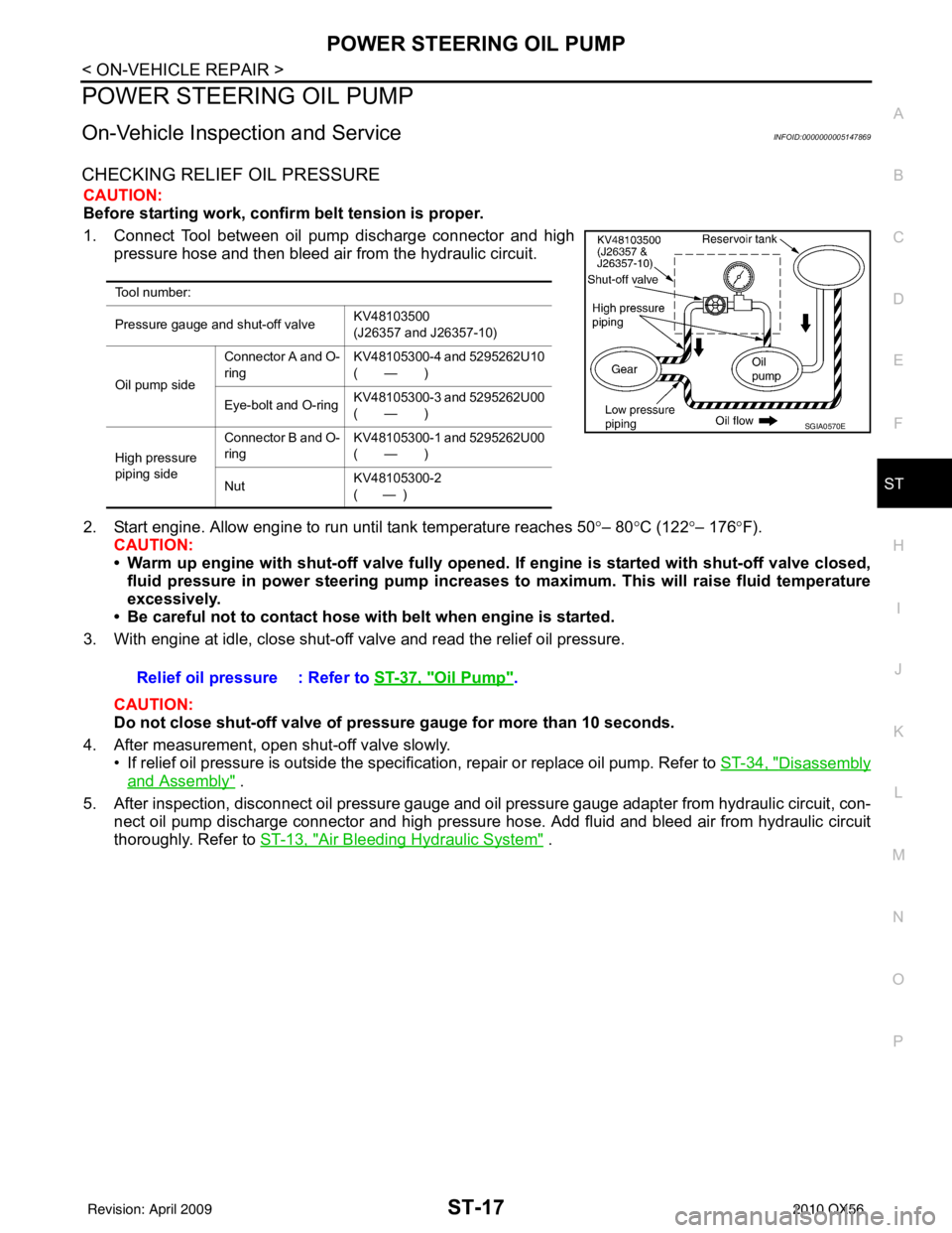
1. Connect Tool between oil pump discharge connector and high pressure hose and then bleed air from the hydraulic circuit.
2. Start engine. Allow engine to run until tank temperature reaches 50 °– 80° C (122° – 176°F).
CAUTION:
• Warm up engine with shut-off valve fully opened. If engine is started with shut-off valve closed,
fluid pressure in power steering pump increases to maximum. This will raise fluid temperature
excessively.
• Be careful not to contact hose with belt when engine is started.
3. With engine at idle, close shut-off valve and read the relief oil pressure.
CAUTION:
Do not close shut-off valve of pressure gauge for more than 10 seconds.
4. After measurement, open shut-off valve slowly. • If relief oil pressure is outside the specification, repair or replace oil pump. Refer to ST-34, "
Disassembly
and Assembly" .
5. After inspection, disconnect oil pressure gauge and oil pressure gauge adapter from hydraulic circuit, con-
nect oil pump discharge connector and high pressure hose. Add fluid and bleed air from hydraulic circuit
thoroughly. Refer to ST-13, "
Air Bleeding Hydraulic System" .
Tool number:
Pressure gauge and shut-off valve KV48103500
(J26357 and J26357-10)
Oil pump side Connector A and O-
ring
KV48105300-4 and 5295262U10
(—)
Eye-bolt and O-ring KV48105300-3 and 5295262U00
(—)
High pressure
piping side Connector B and O-
ring
KV48105300-1 and 5295262U00
(—)
Nut KV48105300-2
( — )
SGIA0570E
Relief oil pressure : Refer to
ST-37, "Oil Pump".
Revision: April 20092010 QX56
Page 3662 of 4210
ST-24
< REMOVAL AND INSTALLATION >
POWER STEERING GEAR AND LINKAGE
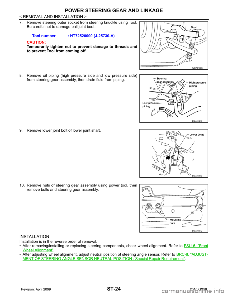
7. Remove steering outer socket from steering knuckle using Tool.Be careful not to damage ball joint boot.
CAUTION:
Temporarily tighten nut to prevent damage to threads and
to prevent Tool from coming off.
8. Remove oil piping (high pressure side and low pressure side) from steering gear assembly, then drain fluid from piping.
9. Remove lower joint bolt of lower joint shaft.
10. Remove nuts of steering gear assembly using power tool, then remove bolts and steering gear assembly.
INSTALLATION
Installation is in the reverse order of removal.
• After removing/installing or replacing steering components, check wheel alignment. Refer to FSU-6, "
Front
Wheel Alignment".
• After adjusting wheel alignment, adjust neutral position of steering angle sensor. Refer to BRC-8, "
ADJUST-
MENT OF STEERING ANGLE SENSOR NEUTRAL POSITION : Special Repair Requirement".
Tool number : HT72520000 (J-25730-A)
WGIA0130E
LGIA0032E
LGIA0029E
LGIA0024E
Revision: April 20092010 QX56
Page 3664 of 4210
ST-26
< REMOVAL AND INSTALLATION >
POWER STEERING OIL PUMP
POWER STEERING OIL PUMP
Removal and InstallationINFOID:0000000005147874
REMOVAL
1. Drain power steering fluid from reservoir tank.
2. Remove engine room cover. Refer to EM-24, "
Removal and Installation".
3. Remove air duct assembly. Refer to EM-25, "
Removal and Installation".
4. Remove power steering reservoir tank.
5. Remove serpentine drive belt belt from auto tensioner and power steering pump. Refer to EM-13,
"Removal and Installation".
6. Disconnect pressure sensor electrical connector.
7. Remove high pressure and low pressure piping from power steering oil pump. Refer to ST-27
.
8. Remove bolts, then remove power steering pump.
INSTALLATION
Installation is in the reverse order of removal. Refer to ST-27 for tightening torque.
• After installation, bleed air. Refer to ST-13, "
Air Bleeding Hydraulic System".
NOTE:
Belt tension is automatic and requires no adjustment.
Revision: April 20092010 QX56