steering wheel adjustment INFINITI QX56 2010 Factory Owner's Manual
[x] Cancel search | Manufacturer: INFINITI, Model Year: 2010, Model line: QX56, Model: INFINITI QX56 2010Pages: 4210, PDF Size: 81.91 MB
Page 2911 of 4210

PG
PG-1
ELECTRICAL & POWER CONTROL
C
DE
F
G H
I
J
K L
B
SECTION PG
A
O P
N
CONTENTS
POWER SUPPLY, GROUND & CIRCUIT ELEMENTS
PRECAUTION .......
........................................2
PRECAUTIONS .............................................. .....2
Precaution for Supplemental Restraint System
(SRS) "AIR BAG" and "SEAT BELT PRE-TEN-
SIONER" ............................................................. ......
2
Precaution Necessary for Steering Wheel Rota-
tion After Battery Disconnect ............................... ......
2
Precaution for Power Generation Variable Voltage
Control System ..........................................................
3
PREPARATION ............................................4
PREPARATION .............................................. .....4
Special Service Tool ........................................... ......4
Commercial Service Tool ..........................................4
BASIC INSPECTION ....................................5
BATTERY ....................................................... .....5
How to Handle Battery ........................................ ......5
Work Flow ........................................................... ......7
INSPECTION AND ADJUSTMENT .....................8
ADDITIONAL SERVICE WHEN REMOVING BAT-
TERY NEGATIVE TERMINAL ............................... ......
8
ADDITIONAL SERVICE WHEN REMOVING
BATTERY NEGATIVE TERMINAL : Special Re-
pair Requirement ................................................. ......
8
COMPONENT DIAGNOSIS ..........................9
POWER SUPPLY ROUTING CIRCUIT .......... .....9
Wiring Diagram — Battery Power Supply — ....... ......9
Wiring Diagram — Accessory Power Supply — .....18
Wiring Diagram — Ignition Power Supply — ..........22
Fuse ........................................................................30
Fusible Link .............................................................30
GROUND ...........................................................31
Ground Distribution .............................................. ....31
HARNESS .........................................................41
Harness Layout ................................................... ....41
ELECTRICAL UNITS LOCATION ....................61
Electrical Units Location ..........................................61
HARNESS CONNECTOR .................................64
Description ...............................................................64
STANDARDIZED RELAY .................................67
Description ...............................................................67
FUSE BLOCK - JUNCTION BOX (J/B) ............69
Terminal Arrangement .............................................69
FUSE, FUSIBLE LINK AND RELAY BOX ........70
Terminal Arrangement .............................................70
IPDM E/R (INTELLIGENT POWER DISTRI-
BUTION MODULE ENGINE ROOM) ................
72
IPDM E/R Terminal Arrangement - Type A .............72
IPDM E/R Terminal Arrangement - Type B .............73
ON-VEHICLE REPAIR .................................74
BATTERY ..........................................................74
Removal and Installation ..................................... ....74
SERVICE DATA AND SPECIFICATIONS
(SDS) ............... .......................................... ...
75
SERVICE DATA AND SPECIFICATIONS
(SDS) .................................................................
75
Battery ................................................................. ....75
Revision: April 20092010 QX56
Page 3473 of 4210

SN
SN-1
DRIVER INFORMATION & MULTIMEDIA
C
DE
F
G H
I
J
K L
M B
SECTION SN
A
O P
CONTENTS
SONAR SYSTEM
BASIC INSPECTION ....... .............................3
DIAGNOSIS AND REPAIR WORKFLOW ..... .....3
Work Flow ........................................................... ......3
INSPECTION AND ADJUSTMENT .....................5
Preliminary Check ............................................... ......5
FUNCTION DIAGNOSIS ...............................6
REAR SONAR SYSTEM ................................ .....6
System Diagram .................................................. ......6
System Description ...................................................6
Component Parts Location ........................................7
Component Description .............................................7
Self-Diagnosis Function ............................................7
FRONT AND REAR SONAR SYSTEM .......... ....10
System Diagram .................................................. ....10
System Description .................................................10
Component Parts Location ......................................11
Component Description ...........................................12
CONSULT-III Function (SONAR) ............................12
COMPONENT DIAGNOSIS .........................13
POWER SUPPLY AND GROUND CIRCUIT .. ....13
Diagnosis Procedure (With Rear Sonar System) ....13
Diagnosis Procedure (With Front and Rear Sonar
System) ............................................................... ....
13
SONAR SENSOR CIRCUIT INSPECTION ........15
Description .......................................................... ....15
Diagnosis Procedure (With Rear Sonar System) ....15
Diagnosis Procedure (With Front and Rear Sonar
System) ...................................................................
15
SONAR BUZZER CIRCUIT INSPECTION .........17
Description .......................................................... ....17
Diagnosis Procedure (With Rear Sonar System) ....17
Diagnosis Procedure (With Front and Rear Sonar
System) ...................................................................
17
Component Inspection ......................................... ....18
SONAR SYSTEM OFF SWITCH CIRCUIT IN-
SPECTION ........................................................
19
Description ........................................................... ....19
Diagnosis Procedure (With Rear Sonar System) ....19
Diagnosis Procedure (With Front and Rear Sonar
System) ............................................................... ....
19
Component Inspection .............................................20
ECU DIAGNOSIS .........................................21
SONAR CONTROL UNIT FOR REAR SONAR
SYSTEM ...................... ......................................
21
Reference Value .................................................. ....21
Wiring Diagram ........................................................23
DTC Index ...............................................................30
SONAR CONTROL UNIT FOR FRONT AND
REAR SONAR SYSTEM ...................................
31
Reference Value ......................................................31
Wiring Diagram ........................................................33
DTC Index ...............................................................44
SYMPTOM DIAGNOSIS ..............................45
SONAR SYSTEM SYMPTOMS ........................45
Symptom Table ................................................... ....45
PRECAUTION ..............................................46
PRECAUTION ...................................................46
Precaution for Supplemental Restraint System
(SRS) "AIR BAG" and "SEAT BELT PRE-TEN-
SIONER" ............................................................. ....
46
Precaution Necessary for Steering Wheel Rota-
tion After Battery Disconnect ...................................
46
PREPARATION ...........................................48
PREPARATION .................................................48
Commercial Service Tool .................................... ....48
Revision: April 20092010 QX56
Page 3531 of 4210

SR-8
< ON-VEHICLE REPAIR >
SPIRAL CABLE
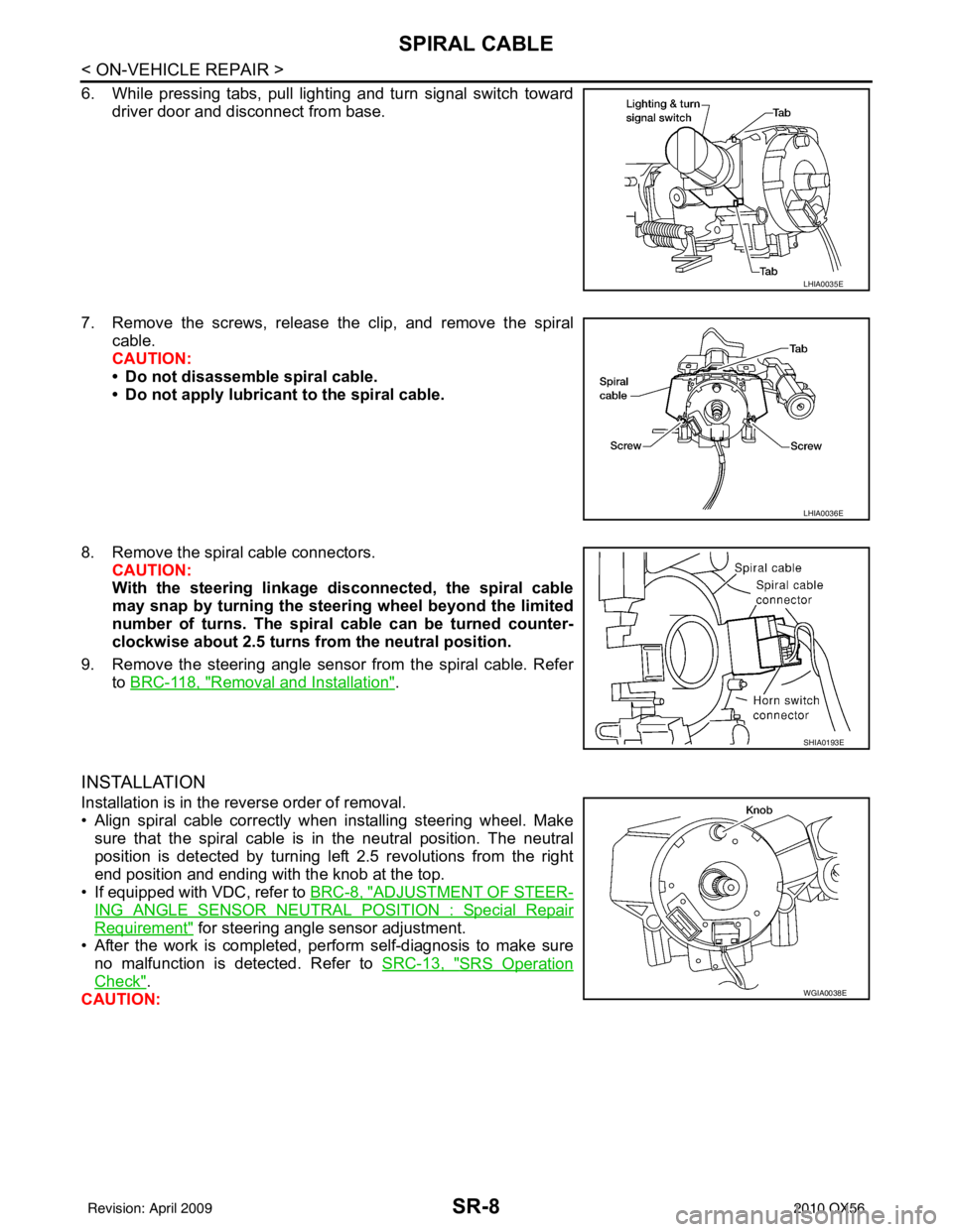
6. While pressing tabs, pull lighting and turn signal switch towarddriver door and disconnect from base.
7. Remove the screws, release the clip, and remove the spiral cable.
CAUTION:
• Do not disassemble spiral cable.
• Do not apply lubricant to the spiral cable.
8. Remove the spiral cable connectors. CAUTION:
With the steering linkage di sconnected, the spiral cable
may snap by turning the steer ing wheel beyond the limited
number of turns. The spiral cable can be turned counter-
clockwise about 2.5 turns fr om the neutral position.
9. Remove the steering angle sensor from the spiral cable. Refer to BRC-118, "
Removal and Installation".
INSTALLATION
Installation is in the reverse order of removal.
• Align spiral cable correctly when installing steering wheel. Make
sure that the spiral cable is in the neutral position. The neutral
position is detected by turning left 2.5 revolutions from the right
end position and ending with the knob at the top.
• If equipped with VDC, refer to BRC-8, "
ADJUSTMENT OF STEER-
ING ANGLE SENSOR NEUTRAL POSITION : Special Repair
Requirement" for steering angle sensor adjustment.
• After the work is completed, perform self-diagnosis to make sure no malfunction is detected. Refer to SRC-13, "
SRS Operation
Check".
CAUTION:
LHIA0035E
LHIA0036E
SHIA0193E
WGIA0038E
Revision: April 20092010 QX56
Page 3656 of 4210

ST-18
< REMOVAL AND INSTALLATION >
STEERING WHEEL
REMOVAL AND INSTALLATION
STEERING WHEEL
Removal and InstallationINFOID:0000000005147870
REMOVAL
1. Set the front wheels in the straight-ahead position.
2. Remove the driver air bag module. Refer to SR-5, "
Removal and Installation".
3. Disconnect steering wheel switches.
4. Remove the steering wheel center nut.
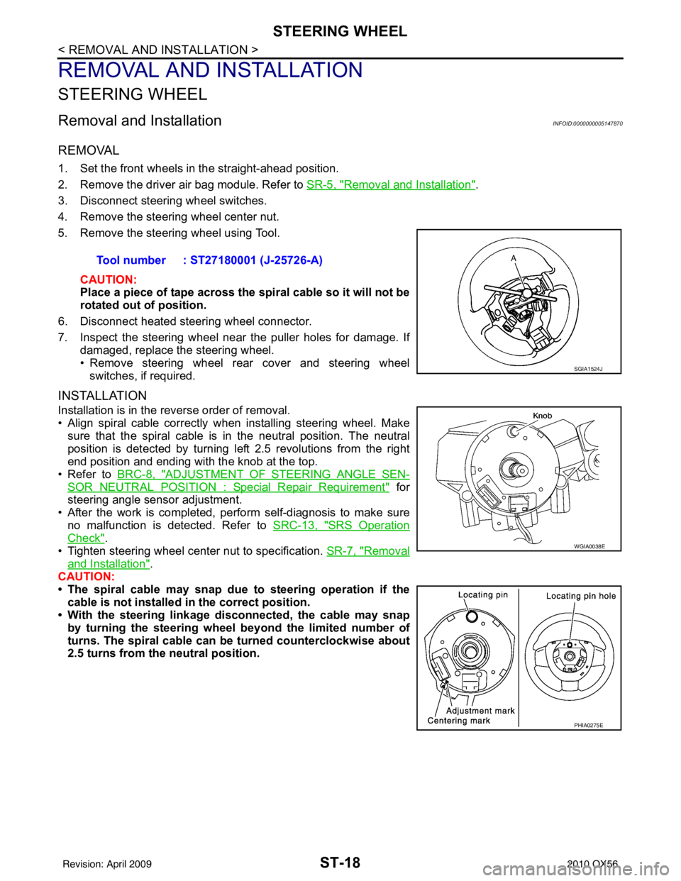
5. Remove the steering wheel using Tool.
CAUTION:
Place a piece of tape across the sp iral cable so it will not be
rotated out of position.
6. Disconnect heated steering wheel connector.
7. Inspect the steering wheel near the puller holes for damage. If damaged, replace the steering wheel.
• Remove steering wheel rear cover and steering wheelswitches, if required.
INSTALLATION
Installation is in the reverse order of removal.
• Align spiral cable correctly when installing steering wheel. Makesure that the spiral cable is in the neutral position. The neutral
position is detected by turning left 2.5 revolutions from the right
end position and ending with the knob at the top.
• Refer to BRC-8, "
ADJUSTMENT OF STEERING ANGLE SEN-
SOR NEUTRAL POSITION : Special Repair Requirement" for
steering angle sensor adjustment.
• After the work is completed, perform self-diagnosis to make sure no malfunction is detected. Refer to SRC-13, "
SRS Operation
Check".
• Tighten steering wheel center nut to specification. SR-7, "
Removal
and Installation".
CAUTION:
• The spiral cable may snap due to steering operation if the
cable is not installed in the correct position.
• With the steering linkage di sconnected, the cable may snap
by turning the steering wheel beyond the limited number of
turns. The spiral cable can be turned counterclockwise about
2.5 turns from the neutral position. Tool number : ST27180001 (J-25726-A)
SGIA1524J
WGIA0038E
PHIA0275E
Revision: April 20092010 QX56
Page 4120 of 4210

REMOVAL AND INSTALLATIONWT-51
< REMOVAL AND INSTALLATION >
C
DF
G H
I
J
K L
M A
B
WT
N
O P
3. Place wheel on turntable of tire machine. Ensure that transmitter
is 270 degrees from mounting/dismounting head.
NOTE:
Do not touch transmitter with mounting head.
4. Lubricate tire well, and install second side of tire as normal. Ensure that tire does not rotate relative to rim.
5. Inflate tire and balance the wheel and tire assembly. Refer to WT-48, "
Balancing Wheels" .
6. Install Wheel and tire assembly in appropriate wheel position on vehicle.
NOTE:
If replacing the transmitter, t hen transmitter wake up operation
must be performed. Refer to WT-5, "
Transmitter Wake Up Operation" .
7. Adjust neutral position of steering angle sensor. Refer to BRC-8, "
ADJUSTMENT OF STEERING ANGLE
SENSOR NEUTRAL POSITION : Special Repair Requirement" .
WEIA0046E
Revision: April 20092010 QX56
Page 4123 of 4210

WW-2
Reference Value .....................................................57
Terminal Layout ......................................................59
Physical Values ......................................................60
Wiring Diagram .......................................................65
Fail Safe .................................................................68
DTC Index ..............................................................70
SYMPTOM DIAGNOSIS .............................71
WIPER AND WASHER SYSTEM SYMPTOMS
...
71
Symptom Table ................................................... ...71
NORMAL OPERATING CONDITION ................74
Description ........................................................... ...74
FRONT WIPER DOES NOT OPERATE ............75
Description ........................................................... ...75
Diagnosis Procedure ..............................................75
PRECAUTION .............................................77
PRECAUTION ... .............................................. ...77
Precaution for Supplemental Restraint System
(SRS) "AIR BAG" and "SEAT BELT PRE-TEN-
SIONER" .............................................................. ...
77
Precaution Necessary for Steering Wheel Rota-
tion After Battery Disconnect ..................................
77
ON-VEHICLE REPAIR ................................79
FRONT WIPER ARM ...................................... ...79
Front Wiper Arms ................................................. ...79
FRONT WIPER DRIVE ASSEMBLY .................80
Wiper Motor and Linkage ..................................... ...80
FRONT WASHER TUBE ...................................81
Washer Tube Layout ............................................ ...81
FRONT WASHER NOZZLE ..............................82
Washer Nozzle Adjustment .................................. ...82
WASHER TANK ................................................83
Washer Fluid Reservoir ..........................................83
FRONT WASHER PUMP ..................................84
Washer Motor ...................................................... ...84
FRONT WIPER AND WASHER SWITCH .........85
Wiper and Washer Switch .................................... ...85
REAR WIPER AND WASHER SYSTEM ...........86
Rear Wiper Arm ................................................... ...86
Rear Wiper Motor ....................................................86
Rear Washer Nozzle Adjustment ............................87
Rear Washer Tube Layout ......................................88
Rear Washer Nozzle ...............................................88
Rear Wiper and Washer Switch ..............................88
Washer Fluid Reservoir ....................................... ...89
Washer Motor .........................................................89
Revision: April 20092010 QX56