check oil INFINITI QX56 2010 Factory Service Manual
[x] Cancel search | Manufacturer: INFINITI, Model Year: 2010, Model line: QX56, Model: INFINITI QX56 2010Pages: 4210, PDF Size: 81.91 MB
Page 187 of 4210
PRECAUTIONSADP-173
< PRECAUTION >
C
DE
F
G H
I
K L
M A
B
ADP
N
O P
5. When the repair work is completed, return the ignition switch to the ″LOCK ″ position before connecting
the battery cables. (At this time, the steering lock mechanism will engage.)
6. Perform a self-diagnosis check of al l control units using CONSULT-III.
Precaution for WorkINFOID:0000000005147589
• When removing or disassembling each component, be ca reful not to damage or deform it. If a component
may be subject to interference, be sure to protect it with a shop cloth.
• When removing (disengaging) components with a screwdriver or similar tool, be sure to wrap the component
with a shop cloth or vinyl tape to protect it.
• Protect the removed parts with a shop cloth and keep them.
• Replace a deformed or damaged clip.
• If a part is specified as a non-reusable part, always replace it with new one.
• Be sure to tighten bolts and nuts securely to the specified torque.
• After re-installation is completed, be sure to check that each part works normally.
• Follow the steps below to clean components.
- Water soluble foul: Dip a soft cloth into lukewarm water, and wring the water out of the cloth to wipe the fouled area.
Then rub with a soft and dry cloth.
- Oily foul: Dip a soft cloth into lukewarm water with mild detergent (concentration: within 2 to 3%), and wipe the fouled area.
Then dip a cloth into fresh water, and wring the water out of the cloth to wipe the detergent off. Then rub with
a soft and dry cloth.
• Do not use organic solvent such as thinner, benzene, alcohol, or gasoline.
• For genuine leather seats, use a genuine leather seat cleaner.
Revision: April 20092010 QX56
Page 355 of 4210
![INFINITI QX56 2010 Factory Service Manual AV-158
< SYMPTOM DIAGNOSIS >[AUDIO SYSTEM]
NORMAL OPERATING CONDITION
NORMAL OPERATING CONDITION
DescriptionINFOID:0000000005146353
AUDIO SYSTEM
The majority of the audio troubles are the result of
o INFINITI QX56 2010 Factory Service Manual AV-158
< SYMPTOM DIAGNOSIS >[AUDIO SYSTEM]
NORMAL OPERATING CONDITION
NORMAL OPERATING CONDITION
DescriptionINFOID:0000000005146353
AUDIO SYSTEM
The majority of the audio troubles are the result of
o](/img/42/57032/w960_57032-354.png)
AV-158
< SYMPTOM DIAGNOSIS >[AUDIO SYSTEM]
NORMAL OPERATING CONDITION
NORMAL OPERATING CONDITION
DescriptionINFOID:0000000005146353
AUDIO SYSTEM
The majority of the audio troubles are the result of
outside causes (bad CD, electromagnetic interference,
etc.).
Noise
The following noise results from variations in field strength, such as fading noise and multi-path noise, or
external noise from trains and other sources. It is not a malfunction.
• Fading noise: This noise occurs because of variations in the field strength in a narrow range due to moun-
tains or buildings blocking the signal.
• Multi-path noise: This noise results from the waves s ent directly from the broadcast station arriving at the
antenna at a different time from the waves which reflect off mountains or buildings.
The vehicle itself can be a source of noise if noise prevention parts or electrical equipment is malfunctioning.
Check if noise is caused and/or changed by engine speed, ignition switch turned to each position, and opera-
tion of each piece of electrical equipment, and determine the cause.
NOTE:
The source of the noise can be found easily by listening to the noise while removing the fuses of electrical
components, one by one.
Type of Noise and Possible Cause
NAVIGATION SYSTEM
Basic Operation
Vehicle Mark
Occurrence condition Possible cause
Occurs only when engine is ON. A continuous growling noise occurs. The speed of
the noise varies with changes in the engine speed. • Ignition components
The occurrence of the noise is linked with the operation of the fuel pump. • Fuel pump condenser
Noise only occurs when various
electrical components are oper-
ating. A cracking or snapping sound occurs with the op-
eration of various switches.
• Relay malfunction, AV control unit malfunc-
tion
The noise occurs when various motors are operat-
ing. • Motor case ground
• Motor
The noise occurs constantly, not just under certain conditions. • Rear defogger coil malfunction
• Open circuit in printed heater
• Poor ground of antenna feeder line
A cracking or snapping sound occurs while the vehicle is being driven, especially when
it is vibrating excessively. • Ground wire of body parts
• Ground due to improper part installation
• Wiring connections or a short circuit
Symptom
Cause Remedy
No image is shown. Display brightness adjustment is set fully to DARK
side. Adjust the display brightness.
No guide sound is heard.
Audio guide volume is too low or
too high. Volume control is set to OFF, MIN or MAX. Adjust the audio guide volume.
Audio guidance is not available while the vehicle is
driving on a dark pink route.
System is not malfunctioning.
Screen is too dark.
Motion of the image is too slow. Temperature inside the vehicle is low.
Wait until the temperature inside the vehicle
reaches the proper temperature.
Small black or bright spots appear
on the screen. Symptom peculiar to a liquid crystal display (dis-
play unit). System is not malfunction.
Revision: April 20092010 QX56
Page 414 of 4210
![INFINITI QX56 2010 Factory Service Manual BCS-28
< FUNCTION DIAGNOSIS >[BCM]
DIAGNOSIS SYSTEM (BCM)
SIGNAL BUFFER : CONSULT-III Fu nction (BCM - SIGNAL BUFFER)
INFOID:0000000005146411
DATA MONITOR
ACTIVE TEST
AIR PRESSURE MONITOR
AIR PRESSURE INFINITI QX56 2010 Factory Service Manual BCS-28
< FUNCTION DIAGNOSIS >[BCM]
DIAGNOSIS SYSTEM (BCM)
SIGNAL BUFFER : CONSULT-III Fu nction (BCM - SIGNAL BUFFER)
INFOID:0000000005146411
DATA MONITOR
ACTIVE TEST
AIR PRESSURE MONITOR
AIR PRESSURE](/img/42/57032/w960_57032-413.png)
BCS-28
< FUNCTION DIAGNOSIS >[BCM]
DIAGNOSIS SYSTEM (BCM)
SIGNAL BUFFER : CONSULT-III Fu nction (BCM - SIGNAL BUFFER)
INFOID:0000000005146411
DATA MONITOR
ACTIVE TEST
AIR PRESSURE MONITOR
AIR PRESSURE MONITOR : Diagnosis DescriptionINFOID:0000000005146412
DESCRIPTION
During driving, the TPMS receives the signal transmitt ed from the transmitter installed in each wheel, when
the tire pressure becomes low. The control unit (BCM ) of this system has pressure judgment and trouble diag-
nosis functions.
When the TPMS detects low inflation pressure or another unusual symptom, the warning lamps in the combi-
nation meter comes on.
SELF DIAGNOSIS (WITH CONSULT-III)
With CONSULT-III
• Touch “SELF-DIAG RESULTS” display to show malfunction experienced since the last erasing operation. Refer to WT-11, "
CONSULT-III Function (BCM)".
SELF DIAGNOSIS (WITHOUT CONSULT-III)
Without CONSULT-III
To start the self-diagnostic results mode, ground terminal of the tire pressure warning check connector. The
malfunction location is indicated by the warning lamp flashing.
NOTE:
When the low tire warning lamp flashes 5 Hz and continues repeating it, the system is normal.
Monitor Item
[Unit] Description
OIL PRESS SW [ON/OFF] Displays the status of oil pressure switch received from IPDM E/R via CAN communication.
Test ItemOperation Description
OIL PRESSURE SW OFF OFF
ON
BCM transmits the oil pressure switch signal to the combination meter via CAN communica-
tion, which operates the oil pressure gauge in the combination meter.
SEIA0745E
Flickering
pattern Items
Diagnostic items detected when··· Check item
15 Tire pressure value (Front LH) Front LH tire pressure drops to 181 kPa (1.8 kg/cm, 25.25 psi) or less.
–
16 Tire pressure value (Front RH) Front RH tire pressure drops to 181 kPa (1.8 kg/cm, 25.25 psi) or less.
17 Tire pressure value (Rear RH) Rear RH tire pressure drops to 181 kPa (1.8 kg/cm, 25.25 psi) or less.
18 Tire pressure value (Rear LH) Rear LH tire pressure drops to 181 kPa (1.8 kg/cm, 25.25 psi) or less.
Revision: April 20092010 QX56
Page 449 of 4210
BR-4
< PRECAUTION >
PRECAUTIONS
5. When the repair work is completed, return the ignition switch to the ″LOCK ″ position before connecting
the battery cables. (At this time, the steering lock mechanism will engage.)
6. Perform a self-diagnosis check of a ll control units using CONSULT-III.
Precaution for Brake SystemINFOID:0000000005147886
• Always use recommended brake fluid. Refer to MA-13, "Fluids and Lubricants".
• Do not reuse drained brake fluid.
• Be careful not to splash brake fluid on painted areas.
• To clean or wash all parts of master cylinder, disc brake caliper and wheel cylinder, use clean brake fluid.
• Do not use mineral oils such as gasoline or kerosene. They will ruin rubber parts of the hydraulic system.
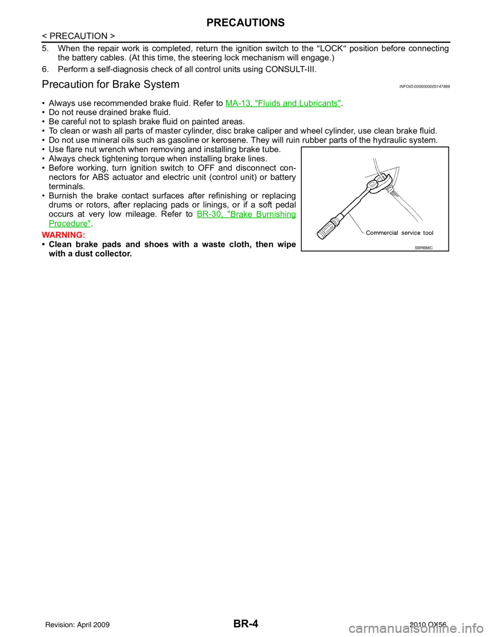
• Use flare nut wrench when removing and installing brake tube.
• Always check tightening torque when installing brake lines.
• Before working, turn ignition switch to OFF and disconnect con- nectors for ABS actuator and electric unit (control unit) or battery
terminals.
• Burnish the brake contact surfaces after refinishing or replacing drums or rotors, after replacing pads or linings, or if a soft pedal
occurs at very low mileage. Refer to BR-30, "
Brake Burnishing
Procedure".
WARNING:
• Clean brake pads and shoes wi th a waste cloth, then wipe
with a dust collector.
SBR686C
Revision: April 20092010 QX56
Page 473 of 4210
BR-28
< ON-VEHICLE REPAIR >
VACUUM LINES
VACUUM LINES
Removal and InstallationINFOID:0000000005147911
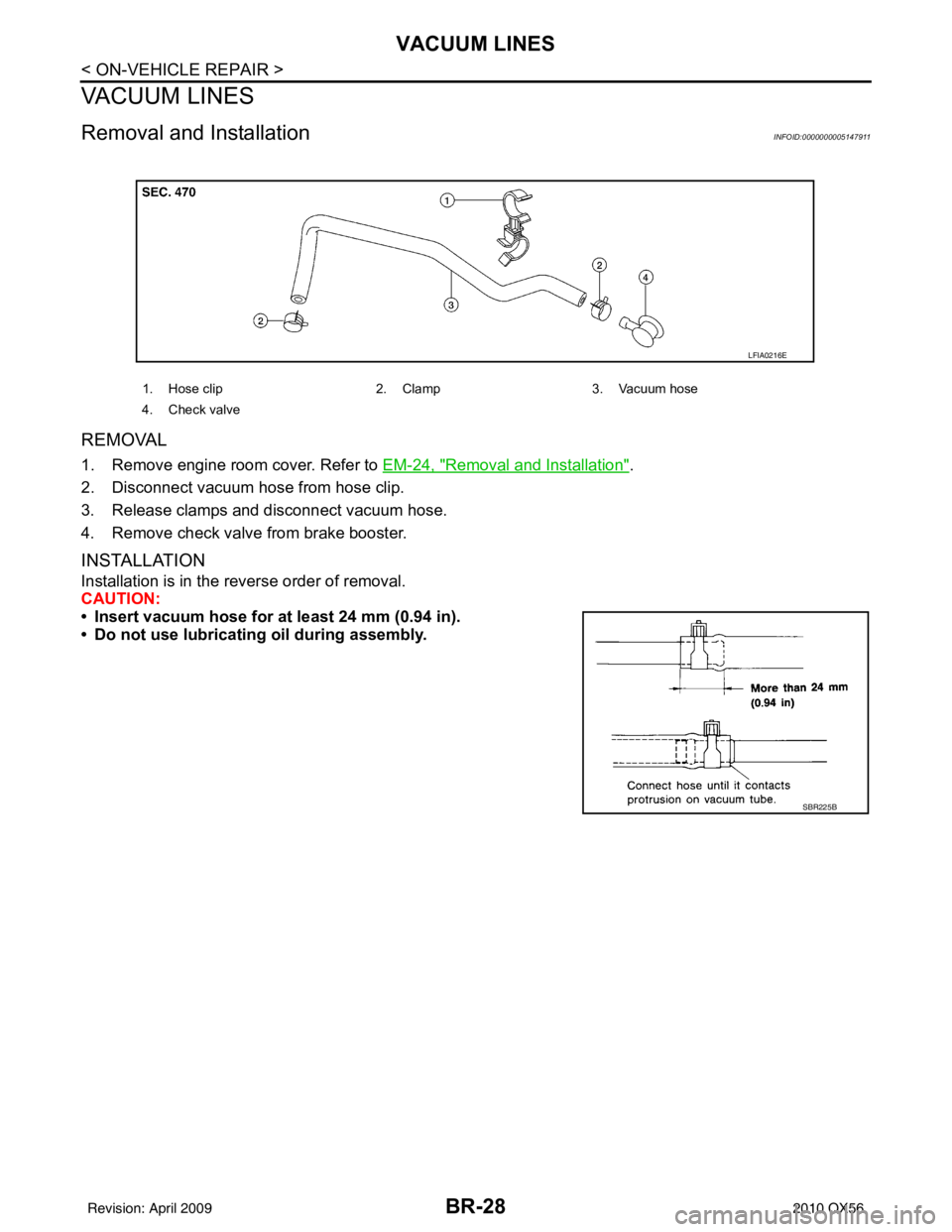
REMOVAL
1. Remove engine room cover. Refer to EM-24, "Removal and Installation".
2. Disconnect vacuum hose from hose clip.
3. Release clamps and disconnect vacuum hose.
4. Remove check valve from brake booster.
INSTALLATION
Installation is in the reverse order of removal.
CAUTION:
• Insert vacuum hose for at least 24 mm (0.94 in).
• Do not use lubricating oil during assembly.
1. Hose clip 2. Clamp3. Vacuum hose
4. Check valve
LFIA0216E
SBR225B
Revision: April 20092010 QX56
Page 485 of 4210
BR-40
< DISASSEMBLY AND ASSEMBLY >
FRONT DISC BRAKE
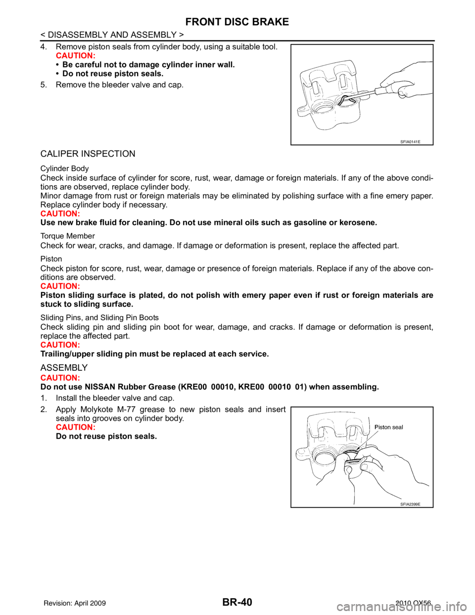
4. Remove piston seals from cylinder body, using a suitable tool.CAUTION:
• Be careful not to damage cylinder inner wall.
• Do not reuse piston seals.
5. Remove the bleeder valve and cap.
CALIPER INSPECTION
Cylinder Body
Check inside surface of cylinder for score, rust, wear, damage or foreign materials. If any of the above condi-
tions are observed, replace cylinder body.
Minor damage from rust or foreign materials may be el iminated by polishing surface with a fine emery paper.
Replace cylinder body if necessary.
CAUTION:
Use new brake fluid for cleaning. Do not use mineral oils such as gasoline or kerosene.
Torque Member
Check for wear, cracks, and damage. If damage or def ormation is present, replace the affected part.
Piston
Check piston for score, rust, wear, damage or presence of foreign materials. Replace if any of the above con-
ditions are observed.
CAUTION:
Piston sliding surface is plated, do not polish with emery paper even if rust or foreign materials are
stuck to sliding surface.
Sliding Pins, and Sliding Pin Boots
Check sliding pin and sliding pin boot for wear, damage, and cracks. If damage or deformation is present,
replace the affected part.
CAUTION:
Trailing/upper slidi ng pin must be replaced at each service.
ASSEMBLY
CAUTION:
Do not use NISSAN Rubber Grease ( KRE00 00010, KRE00 00010 01) when assembling.
1. Install the bleeder valve and cap.
2. Apply Molykote M-77 grease to new piston seals and insert seals into grooves on cylinder body.
CAUTION:
Do not reuse piston seals.
SFIA0141E
SFIA2399E
Revision: April 20092010 QX56
Page 488 of 4210
REAR DISC BRAKEBR-43
< DISASSEMBLY AND ASSEMBLY >
C
DE
G H
I
J
K L
M A
B
BR
N
O P
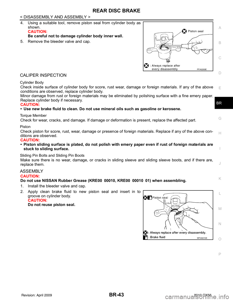
4. Using a suitable tool, remove piston seal from cylinder body as shown.
CAUTION:
Be careful not to damage cylinder body inner wall.
5. Remove the bleeder valve and cap.
CALIPER INSPECTION
Cylinder Body
Check inside surface of cylinder body for score, rust wear, damage or foreign materials. If any of the above
conditions are observed, replace cylinder body.
Minor damage from rust or foreign materials may be eliminated by polishing surface with a fine emery paper.
Replace cylinder body if necessary.
CAUTION:
• Use new brake fluid to clean. Do not use mi neral oils such as gasoline or kerosene.
Torque Member
Check for wear, cracks, and damage. If damage or deformation is present, replace the affected part.
Piston
Check piston for score, rust, wear, damage or presence of foreign materials. Replace if any of the above con-
ditions are observed.
CAUTION:
• Piston sliding surface is plated, do not polish with emery paper even if rust of foreign materials are
stuck to sliding surface.
Sliding Pin Bolts and Sliding Pin Boots
Make sure there is no wear, damage, or cracks in sliding sleeve and sliding sleeve boots, and if there are,
replace them.
ASSEMBLY
CAUTION:
Do not use NISSAN Rubber Grease ( KRE00 00010, KRE00 00010 01) when assembling.
1. Install the bleeder valve and cap.
2. Apply clean brake fluid to new piston seal and insert in to groove on cylinder body.
CAUTION:
Do not reuse piston seal.
PFIA0269E
WFIA0210E
Revision: April 20092010 QX56
Page 603 of 4210
![INFINITI QX56 2010 Factory Service Manual PRECAUTIONSBRC-111
< PRECAUTION > [VDC/TCS/ABS]
C
D
E
G H
I
J
K L
M A
B
BRC
N
O P
5. When the repair work is completed, return the ignition switch to the ″LOCK ″ position before connecting
the ba INFINITI QX56 2010 Factory Service Manual PRECAUTIONSBRC-111
< PRECAUTION > [VDC/TCS/ABS]
C
D
E
G H
I
J
K L
M A
B
BRC
N
O P
5. When the repair work is completed, return the ignition switch to the ″LOCK ″ position before connecting
the ba](/img/42/57032/w960_57032-602.png)
PRECAUTIONSBRC-111
< PRECAUTION > [VDC/TCS/ABS]
C
D
E
G H
I
J
K L
M A
B
BRC
N
O P
5. When the repair work is completed, return the ignition switch to the ″LOCK ″ position before connecting
the battery cables. (At this time, the steering lock mechanism will engage.)
6. Perform a self-diagnosis check of al l control units using CONSULT-III.
Precaution for Brake SystemINFOID:0000000005148094
CAUTION:
• Always use recommended brake fluid. Refer to MA-13, "
Fluids and Lubricants".
• Never reuse drained brake fluid.
• Be careful not to splash brake fluid on painted areas; it may cause paint damage. If brake fluid is
splashed on painted areas, wash it away with water immediately.
• To clean or wash all parts of master cylin der and disc brake caliper, use clean brake fluid.
• Never use mineral oils such as gasoline or kerosen e. They will ruin rubber parts of the hydraulic sys-
tem.
• Use flare nut wrench when removing and installing brake
tube.
• If a brake fluid leak is found, the part must be disassembled
without fail. Then it has to be replaced with a new one if a
defect exists.
• Turn the ignition switch OFF and remove the connector of the ABS actuator and electric unit (con trol unit) or the battery ter-
minal before performing the work.
• Always torque brake lines when installing.
• Burnish the brake contact surf aces after refinishing or replac-
ing rotors, after replacing pads, or if a soft pedal occurs at
very low mileage.
Refer to BR-30, "
Brake Burnishing Procedure" (front disc brake) or BR-35, "Brake Burnishing Proce-
dure" (rear disc brake).
WARNING:
• Clean brake pads and shoes with a waste cl oth, then wipe with a dust collector.
Precaution for Brake ControlINFOID:0000000005148095
• During ABS operation, the brake pedal may vibrate lightly and a mechanical noise may be heard. This is
normal.
• Just after starting vehicle, the brake pedal may vibrate or a motor operating noise may be heard from engine
compartment. This is a normal status of operation check.
• Stopping distance may be longer than that of vehicles without ABS when vehicle drives on rough, gravel, or snow-covered (fresh, deep snow) roads.
• When an error is indicated by ABS or another warning lamp, collect all necessary information from customer (what symptoms are present under what conditions) and check for simple causes before starting diagnosis.
Besides electrical system inspection, check boos ter operation, brake fluid level, and fluid leaks.
• If incorrect tire sizes or types are installed on the vehicle or brake pads are not Genuine NISSAN parts, stop-
ping distance or steering stability may deteriorate.
• If there is a radio, antenna or related wiring near control module, ABS function may have a malfunction or
error.
• If aftermarket parts (car stereo, CD player, etc.) have been installed, check for incidents such as harness pinches, open circuits or improper wiring.
• If the following components are replaced with non-genuine components or modified, the VDC OFF indicator lamp and SLIP indicator lamp may turn on or the VDC system may not operate properly. Components
related to suspension (shock absorbers, struts, springs , bushings, etc.), tires, wheels (exclude specified
size), components related to brake system (pads, roto rs, calipers, etc.), components related to engine (muf-
fler, ECM, etc.), components related to body reinforcement (roll bar, tower bar, etc.).
• Driving with broken or excessively worn suspensi on components, tires or brake system components may
cause the VDC OFF indicator lamp and the SLIP indicator lamp to turn on, and the VDC system may not
operate properly.
• When the TCS or VDC is activated by sudden acceleration or sudden turn, some noise may occur. The noise is a result of the normal operation of the TCS and VDC.
• When driving on roads which have extreme slopes (such as mountainous roads) or high banks (such as sharp curves on a freeway), the VDC may not operate no rmally, or the VDC warning lamp and the SLIP indi-
cator lamp may turn on. This is not a problem if normal operation can be resumed after restarting the engine.
SBR686C
Revision: April 20092010 QX56
Page 674 of 4210
CCS
INSPECTION AND ADJUSTMENTCCS-5
< BASIC INSPECTION >
C
DE
F
G H
I
J
K L
M B
N P A
INSPECTION AND ADJUSTMENT
ADDITIONAL SERVICE WHEN REPLACING CONTROL UNIT
ADDITIONAL SERVICE WHEN REPL ACING CONTROL UNIT : Description
INFOID:0000000005145971
Always perform the laser beam aiming adjustment after repl acing the ICC unit. In addition, test the ICC sys-
tem operations to see if it functions normally.
ADDITIONAL SERVICE WHEN REPLACING CONTROL UNIT : Special Repair Re-
quirement
INFOID:0000000005145972
1.LASER BEAM AIMING ADJUSTMENT
Adjust laser beam aiming. Refer to CCS-5, "
LASER BEAM AIMING ADJUSTMENT : Outline of Laser Beam
Aiming Adjustment Procedure".
>> GO TO 2
2.ICC SYSTEM ACTION TEST
1. Perform the ICC system operation test. Refer to CCS-8, "
ACTION TEST : ICC System Running Test".
2. Check that the ICC system operates normally.
>> INSPECTION END.
LASER BEAM AIMI NG ADJUSTMENT
LASER BEAM AIMING ADJUSTMENT : Outlin e of Laser Beam Aiming Adjustment
Procedure
INFOID:0000000005145973
CAUTION:
• The laser beam aiming adjustment can not be performed without CONSULT-III.
• The laser beam aiming adjustment must be performed every time the ICC sensor is removed,
installed or has been moved as a result of a collision.
1. Prepare the vehicle and the work area.
2. Set up the ICC target board. For details, refer to Technical Service Bulletin.
3. Adjust the sensor following the procedure on CONSULT-III.
4. Check system operation after the adjustment.
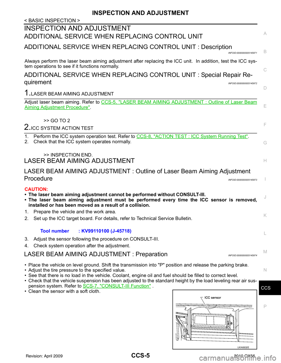
LASER BEAM AIMING ADJU STMENT : PreparationINFOID:0000000005145974
• Place the vehicle on level ground. Shift the transmi ssion into "P" position and release the parking brake.
• Adjust the tire pressure to the specified value.
• See that there is no load in the vehicle. Coolant , engine oil and fuel should be filled to correct level.
• Check that the vehicle suspension has been adjusted to the standard height by the load leveling rear air sus-
pension system. Refer to SCS-7, "
CONSULT-III Function" .
• Clean the sensor with a soft cloth. Tool number : KV99110100 (J-45718)
LKIA0632E
Revision: April 20092010 QX56
Page 704 of 4210
CCS
DTC 90 STOP LAMP RLY FIXCCS-35
< COMPONENT DIAGNOSIS >
C
DE
F
G H
I
J
K L
M B
N P A
1. Disconnect ICC brake hold relay.
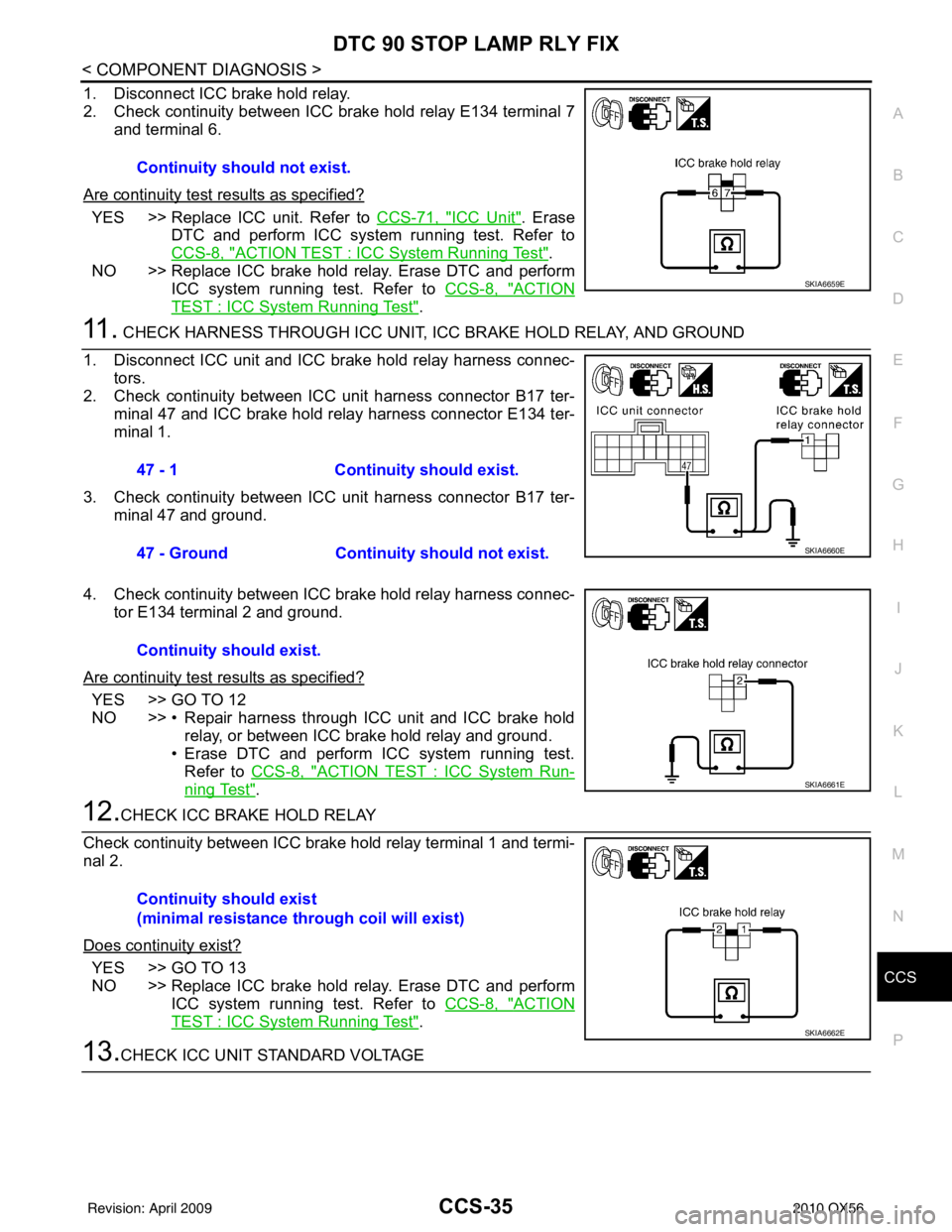
2. Check continuity between ICC brake hold relay E134 terminal 7 and terminal 6.
Are continuity test results as specified?
YES >> Replace ICC unit. Refer to CCS-71, "ICC Unit". Erase
DTC and perform ICC system running test. Refer to
CCS-8, "
ACTION TEST : ICC System Running Test".
NO >> Replace ICC brake hold relay. Erase DTC and perform ICC system running test. Refer to CCS-8, "
ACTION
TEST : ICC System Running Test".
11 . CHECK HARNESS THROUGH ICC UNIT, ICC BRAKE HOLD RELAY, AND GROUND
1. Disconnect ICC unit and ICC brake hold relay harness connec- tors.
2. Check continuity between ICC unit harness connector B17 ter- minal 47 and ICC brake hold relay harness connector E134 ter-
minal 1.
3. Check continuity between ICC unit harness connector B17 ter- minal 47 and ground.
4. Check continuity between ICC brake hold relay harness connec- tor E134 terminal 2 and ground.
Are continuity test results as specified?
YES >> GO TO 12
NO >> • Repair harness through ICC unit and ICC brake hold relay, or between ICC brake hold relay and ground.
• Erase DTC and perform ICC system running test.
Refer to CCS-8, "
ACTION TEST : ICC System Run-
ning Test".
12.CHECK ICC BRAKE HOLD RELAY
Check continuity between ICC brake hold relay terminal 1 and termi-
nal 2.
Does continuity exist?
YES >> GO TO 13
NO >> Replace ICC brake hold relay. Erase DTC and perform ICC system running test. Refer to CCS-8, "
ACTION
TEST : ICC System Running Test".
13.CHECK ICC UNIT STANDARD VOLTAGE
Continuity should not exist.
SKIA6659E
47 - 1
Continuity should exist.
47 - Ground Continuity should not exist.
SKIA6660E
Continuity should exist.
SKIA6661E
Continuity should exist
(minimal resistance through coil will exist)
SKIA6662E
Revision: April 20092010 QX56