check engine INFINITI QX56 2010 Factory Service Manual
[x] Cancel search | Manufacturer: INFINITI, Model Year: 2010, Model line: QX56, Model: INFINITI QX56 2010Pages: 4210, PDF Size: 81.91 MB
Page 2735 of 4210

CHASSIS AND BODY MAINTENANCEMA-31
< ON-VEHICLE MAINTENANCE >
C
DE
F
G H
I
J
K L
M B
MA
N
O A
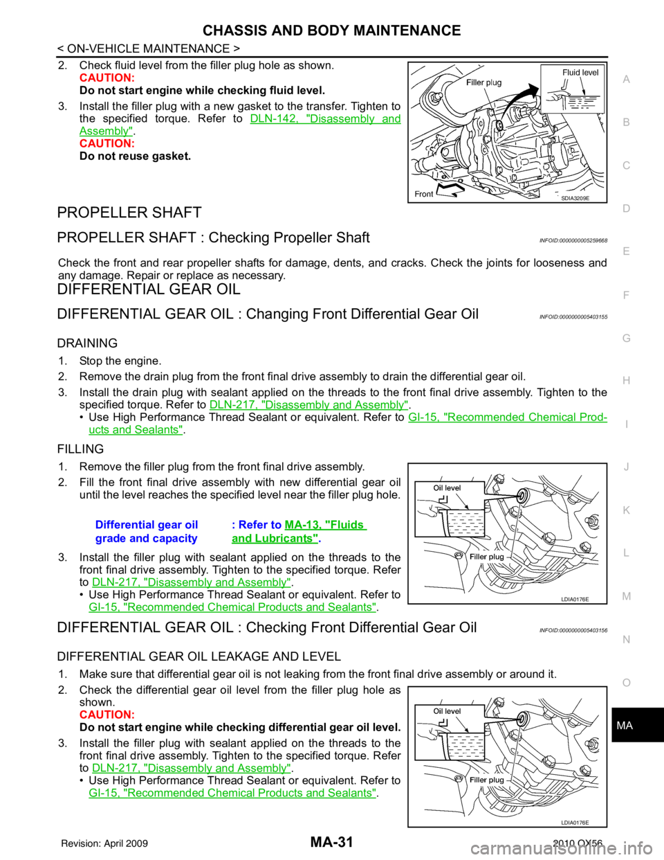
2. Check fluid level from the filler plug hole as shown.
CAUTION:
Do not start engine while checking fluid level.
3. Install the filler plug with a new gasket to the transfer. Tighten to the specified torque. Refer to DLN-142, "
Disassembly and
Assembly".
CAUTION:
Do not reuse gasket.
PROPELLER SHAFT
PROPELLER SHAFT : Checking Propeller ShaftINFOID:0000000005259668
Check the front and rear propeller shafts for damage, dents, and cracks. Check the joints for looseness and
any damage. Repair or replace as necessary.
DIFFERENTIAL GEAR OIL
DIFFERENTIAL GEAR OIL : Changing Front Differential Gear OilINFOID:0000000005403155
DRAINING
1. Stop the engine.
2. Remove the drain plug from the front final drive assembly to drain the differential gear oil.
3. Install the drain plug with sealant applied on the thr eads to the front final drive assembly. Tighten to the
specified torque. Refer to DLN-217, "
Disassembly and Assembly".
• Use High Performance Thread Sealant or equivalent. Refer to GI-15, "
Recommended Chemical Prod-
ucts and Sealants".
FILLING
1. Remove the filler plug from the front final drive assembly.
2. Fill the front final drive assembly with new differential gear oil
until the level reaches the specified level near the filler plug hole.
3. Install the filler plug with sealant applied on the threads to the front final drive assembly. Tighten to the specified torque. Refer
to DLN-217, "
Disassembly and Assembly".
• Use High Performance Thread Sealant or equivalent. Refer to GI-15, "
Recommended Chemical Products and Sealants".
DIFFERENTIAL GEAR OIL : Checking Front Differential Gear OilINFOID:0000000005403156
DIFFERENTIAL GEAR OIL LEAKAGE AND LEVEL
1. Make sure that differential gear oil is not leaking from the front final drive assembly or around it.
2. Check the differential gear oil level from the filler plug hole as
shown.
CAUTION:
Do not start engine while checki ng differential gear oil level.
3. Install the filler plug with sealant applied on the threads to the front final drive assembly. Tighten to the specified torque. Refer
to DLN-217, "
Disassembly and Assembly".
• Use High Performance Thread Sealant or equivalent. Refer to GI-15, "
Recommended Chemical Products and Sealants".
SDIA3209E
Differential gear oil
grade and capacity : Refer to
MA-13, "Fluids
and Lubricants".
LDIA0176E
LDIA0176E
Revision: April 20092010 QX56
Page 2736 of 4210

MA-32
< ON-VEHICLE MAINTENANCE >
CHASSIS AND BODY MAINTENANCE
DIFFERENTIAL GEAR OIL : Changi ng Rear Differential Gear Oil
INFOID:0000000005403157
DRAINING
1. Stop the engine.
2. Remove the drain plug and gasket from the rear final drive
assembly to drain the differential gear oil.
3. Install the drain plug with a new gasket to the rear final drive assembly. Tighten to the specified torque. Refer to DLN-253,
"Disassembly and Assembly".
CAUTION:
Do not reuse gasket.
FILLING
1. Remove the filler plug and gasket from the rear final drive assembly.
2. Fill the rear final drive assembly with new differential gear oil until the level reaches the specified level near the filler plug hole.
3. Install the filler plug with a new gasket on it to the rear final drive assembly. Tighten to the specified torque. Refer to DLN-253,
"Disassembly and Assembly".
CAUTION:
Do not reuse gasket.
DIFFERENTIAL GEAR OIL : Checking Rear Differential Gear OilINFOID:0000000005403158
OIL LEAKAGE AND OIL LEVEL
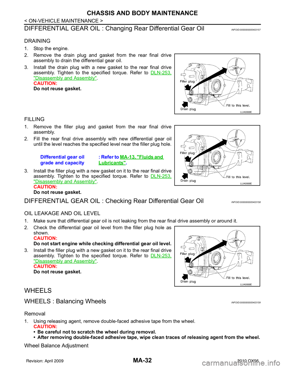
1. Make sure that differential gear oil is not leaki ng from the rear final drive assembly or around it.
2. Check the differential gear oil level from the filler plug hole as shown.
CAUTION:
Do not start engine while checki ng differential gear oil level.
3. Install the filler plug with a new gasket on it to the rear final drive assembly. Tighten to the specified torque. Refer to DLN-253,
"Disassembly and Assembly".
CAUTION:
Do not reuse gasket.
WHEELS
WHEELS : Balancing WheelsINFOID:0000000005403159
Removal
1. Using releasing agent, remove double-faced adhesive tape from the wheel. CAUTION:
• Be careful not to scratch the wheel during removal.
• After removing double-faced adh esive tape, wipe clean traces of releasing agent from the wheel.
Wheel Balance Adjustment
LLIA0068E
Differential gear oil
grade and capacity: Refer to MA-13, "Fluids and
Lubricants".
LLIA0068E
LLIA0068E
Revision: April 20092010 QX56
Page 2738 of 4210

MA-34
< ON-VEHICLE MAINTENANCE >
CHASSIS AND BODY MAINTENANCE
Wheel balance (Maximum allowable imbalance):
WHEELS : RotationINFOID:0000000005403160
NOTE:
Follow the maintenance schedule for tire rotation service intervals. Refer to MA-9, "
Schedule 1" .
1. Rotate the tires on each side from front to back as shown. Do not include the spare tire when rotating the tires.
CAUTION:
When installing wheel s, tighten them diagonally by dividing
the work two to three times in order to prevent the wheels
from developing any distortion.
2. Adjust the tire pressure to specification. Refer to WT-52, "
Tire" .
3. After the tire rotation, retighten the wheel nuts after the vehicle has been driven for 1,000 km (600 miles), and also after every
wheel and tire have been installed such as after repairing a flat tire.
BRAKE FLUID LEVEL AND LEAKS
BRAKE FLUID LEVEL AND LEAK S : On Board InspectionINFOID:0000000005403161
LEVEL CHECK
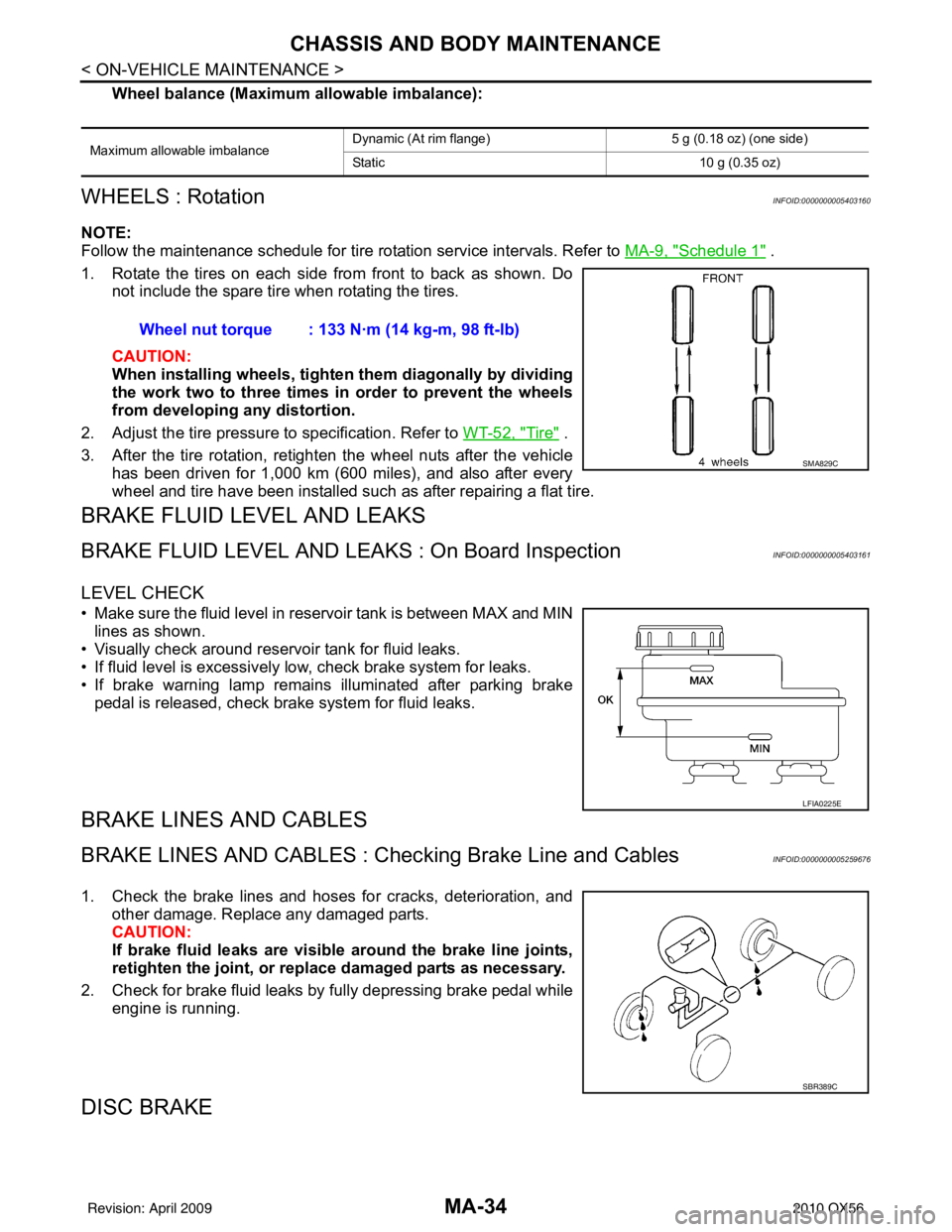
• Make sure the fluid level in reservoir tank is between MAX and MIN
lines as shown.
• Visually check around reservoir tank for fluid leaks.
• If fluid level is excessively low, check brake system for leaks.
• If brake warning lamp remains illuminated after parking brake pedal is released, check brake system for fluid leaks.
BRAKE LINES AND CABLES
BRAKE LINES AND CABLES : Ch ecking Brake Line and CablesINFOID:0000000005259676
1. Check the brake lines and hoses for cracks, deterioration, and
other damage. Replace any damaged parts.
CAUTION:
If brake fluid leaks are visible around the brake line joints,
retighten the joint, or replace damaged parts as necessary.
2. Check for brake fluid leaks by fully depressing brake pedal while engine is running.
DISC BRAKE
Maximum allowable imbalance Dynamic (At rim flange) 5 g (0.18 oz) (one side)
Static
10 g (0.35 oz)
Wheel nut torque : 133 N·m (14 kg-m, 98 ft-lb)
SMA829C
LFIA0225E
SBR389C
Revision: April 20092010 QX56
Page 2741 of 4210

CHASSIS AND BODY MAINTENANCEMA-37
< ON-VEHICLE MAINTENANCE >
C
DE
F
G H
I
J
K L
M B
MA
N
O A
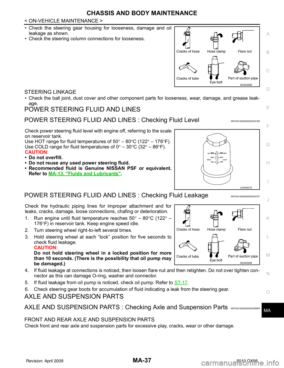
• Check the steering gear housing for looseness, damage and oil
leakage as shown.
• Check the steering column connections for looseness.
STEERING LINKAGE
• Check the ball joint, dust cover and other component parts for looseness, wear, damage, and grease leak-
age.
POWER STEERING FLUID AND LINES
POWER STEERING FLUID AND LINE S : Checking Fluid LevelINFOID:0000000005403166
Check power steering fluid level with engine off, referring to the scale
on reservoir tank.
Use HOT range for fluid temperatures of 50 ° – 80 °C (122 ° – 176 °F).
Use COLD range for fluid temperatures of 0 ° – 30 °C (32° – 86°F).
CAUTION:
• Do not overfill.
• Do not reuse any used power steering fluid.
• Recommended fluid is Genuine NISSAN PSF or equivalent.
Refer to MA-13, "
Fluids and Lubricants".
POWER STEERING FLUID AND LINES : Checking Fluid LeakageINFOID:0000000005403167
Check the hydraulic piping lines for improper attachment and for
leaks, cracks, damage, loose connec tions, chafing or deterioration.
1. Run engine until fluid temperature reaches 50 ° – 80° C (122° –
176° F) in reservoir tank. Keep engine speed idle.
2. Turn steering wheel right-to-left several times.
3. Hold steering wheel at each “lock” position for five seconds to check fluid leakage.
CAUTION:
Do not hold steering wheel in a locked position for more
than 10 seconds. (There is the possibility that oil pump may
be damaged.)
4. If fluid leakage at connections is noticed, then loosen flare nut and then retighten. Do not over tighten con- nector as this can damage O-ring, washer and connector.
5. If fluid leakage from oil pump is noticed, check oil pump. Refer to ST-17
.
6. Check steering gear boots for accumulation of fluid indicating a leak from the steering gear.
AXLE AND SUSPENSION PARTS
AXLE AND SUSPENSION PARTS : Chec king Axle and Suspension PartsINFOID:0000000005259684
FRONT AND REAR AXLE AND SUSPENSION PARTS
Check front and rear axle and suspension parts for excessive play, cracks, wear or other damage.
SGIA0506E
LGIA0021E
SGIA0506E
Revision: April 20092010 QX56
Page 2764 of 4210

MWI-2
INFORMATION DISPLAY .........................................19
INFORMATION DISPLAY : System Diagram .........20
INFORMATION DISPLAY : System Description ....20
INFORMATION DISPLAY : Component Parts Lo-
cation ................................................................... ...
21
INFORMATION DISPLAY : Component Descrip-
tion ....................................................................... ...
21
DIAGNOSIS SYSTEM (METER) .......................22
Diagnosis Description .......................................... ...22
CONSULT-III Function (METER/M&A) ................ ...23
COMPONENT DIAGNOSIS ........................26
DTC U1000 CAN COMMUNICATION ............ ...26
DTC Logic ............................................................ ...26
Diagnosis Procedure .............................................26
DTC B2205 VEHICLE SPEED CIRCUIT ...........27
Description ........................................................... ...27
DTC Logic ...............................................................27
Diagnosis Procedure .............................................27
POWER SUPPLY AND GROUND CIRCUIT .....28
COMBINATION METER ........................................ ...28
COMBINATION METER : Diagnosis Procedure ....28
BCM (BODY CONTROL MODULE) ...................... ...29
BCM (BODY CONTROL MODULE) : Diagnosis
Procedure ...............................................................
29
IPDM E/R (INTELLIGENT POWER DISTRIBU-
TION MODULE ENGINE ROOM) .......................... ...
30
IPDM E/R (INTELLIGENT POWER DISTRIBU-
TION MODULE ENGINE ROOM) : Diagnosis Pro-
cedure .....................................................................
30
FUEL LEVEL SENSOR SIGNAL CIRCUIT .......32
Description ........................................................... ...32
Component Function Check ...................................32
Diagnosis Procedure .............................................32
Component Inspection ............................................33
OIL PRESSURE SWITCH SIGNAL CIRCUIT ...34
Description ..............................................................34
Component Function Check ...................................34
Diagnosis Procedure ..............................................34
Component Inspection ............................................34
PARKING BRAKE SWITCH SIGNAL CIR-
CUIT ...................................................................
35
Description ........................................................... ...35
Component Function Check ...................................35
Diagnosis Procedure ..............................................35
Component Inspection ............................................35
WASHER LEVEL SWITCH SIGNAL CIRCUIT ...36
Description ........................................................... ...36
Diagnosis Procedure ..............................................36
Component Inspection ............................................36
CLOCK ..............................................................37
Wiring Diagram .................................................... ...37
ECU DIAGNOSIS .......................................39
COMBINATION METER ................................. ...39
Reference Value .................................................. ...39
Wiring Diagram .......................................................41
Fail Safe ..................................................................58
DTC Index ...............................................................59
BCM (BODY CONTROL MODULE) ..................61
Reference Value .................................................. ...61
Terminal Layout ......................................................64
Physical Values .......................................................64
Wiring Diagram .......................................................70
Fail Safe .................................................................74
DTC Inspection Priority Chart ...............................75
DTC Index ..............................................................75
IPDM E/R (INTELLIGENT POWER DISTRI-
BUTION MODULE ENGINE ROOM) .................
77
Reference Value .................................................. ...77
Terminal Layout ......................................................79
Physical Values .......................................................80
Wiring Diagram .......................................................85
Fail Safe .................................................................88
DTC Index ..............................................................90
SYMPTOM DIAGNOSIS ............................91
THE FUEL GAUGE POINTER DOES NOT
MOVE .............................................................. ...
91
Description ........................................................... ...91
Diagnosis Procedure ...............................................91
THE FUEL GAUGE POINTER DOES NOT
MOVE TO "F" WHEN REFUELING ..................
92
Description ........................................................... ...92
Diagnosis Procedure ...............................................92
THE OIL PRESSURE WARNING LAMP
DOES NOT TURN ON .................................... ...
93
Description ........................................................... ...93
Diagnosis Procedure ...............................................93
THE OIL PRESSURE WARNING LAMP
DOES NOT TURN OFF .................................. ...
94
Description ........................................................... ...94
Diagnosis Procedure ...............................................94
THE PARKING BRAKE RELEASE WARNING
CONTINUES DISPLAYING, OR DOES NOT
DISPLAY ............................................................
95
Description ........................................................... ...95
Diagnosis Procedure ...............................................95
THE LOW WASHER FLUID WARNING CON-
TINUES DISPLAYING, or DOES NOT DIS-
PLAY ..................................................................
96
Revision: April 20092010 QX56
Page 2767 of 4210

MWI
METER SYSTEMMWI-5
< FUNCTION DIAGNOSIS >
C
DE
F
G H
I
J
K L
M B A
O P
FUNCTION DIAGNOSIS
METER SYSTEM
METER SYSTEM
METER SYSTEM : System DiagramINFOID:0000000005146025
METER SYSTEM : System DescriptionINFOID:0000000005146026
COMBINATION METER
• Speedometer, odo/trip meter, tachometer, fuel gauge, engine coolant temperature gauge, engine oil pres-
sure gauge, voltage gauge and information display are controlled by the unified meter control unit, which is
built into the combination meter.
• Warning and indicator lamps are controlled by the unified meter control unit and by components connected directly to the combination meter.
• Digital meter is adopted for odo/trip meter.* *The record of the odometer is kept even if the battery cable is disconnected. The record of the trip meter is
erased when the battery cable is disconnected.
• Odo/trip meter segments can be checked in diagnosis mode.
• Meter/gauge can be checked in diagnosis mode.
AWNIA0274GB
Revision: April 20092010 QX56
Page 2786 of 4210
![INFINITI QX56 2010 Factory Service Manual MWI-24
< FUNCTION DIAGNOSIS >
DIAGNOSIS SYSTEM (METER)
X: Applicable
Display item [Unit]MAIN
SIGNALS SELECTION
FROM MENU Description
SPEED METER [km/h] or [mph] X X Displays the value of vehicle spee INFINITI QX56 2010 Factory Service Manual MWI-24
< FUNCTION DIAGNOSIS >
DIAGNOSIS SYSTEM (METER)
X: Applicable
Display item [Unit]MAIN
SIGNALS SELECTION
FROM MENU Description
SPEED METER [km/h] or [mph] X X Displays the value of vehicle spee](/img/42/57032/w960_57032-2785.png)
MWI-24
< FUNCTION DIAGNOSIS >
DIAGNOSIS SYSTEM (METER)
X: Applicable
Display item [Unit]MAIN
SIGNALS SELECTION
FROM MENU Description
SPEED METER [km/h] or [mph] X X Displays the value of vehicle speed signal.
SPEED OUTPUT [km/h] or [mph] X XDisplays the value of vehicle speed signal, which is transmitted to
each unit with
CAN communication.
TACHO METER [rpm] XX Displays the value of engine speed signal, which is input from ECM.
FUEL METER [lit.] XXDisplays the value, which processes a resistance signal from fuel
gauge.
W TEMP METER [ °C] or [° F] X XDisplays the value of engine coolant temperature signal, which is in-
put from ECM.
ABS W/L [ON/OFF] X Displays [ON/OFF] condition of ABS warning lamp.
VDC/TCS IND [ON/OFF] X Displays [ON/OFF] condition of VDC OFF indicator lamp.
SLIP IND [ON/OFF] X Displays [ON/OFF] condition of SLIP indicator lamp.
BRAKE W/L [ON/OFF] X Displays [ON/OFF] condition of brake warning lamp.*
DOOR W/L [ON/OFF] X Displays [ON/OFF] condition of door warning lamp.
TRUNK W/L [ON/OFF] X Displays [ON/OFF] condition of glass hatch warning lamp.
HI-BEAM IND [ON/OFF] X Displays [ON/OFF] condition of high beam indicator.
TURN IND [ON/OFF] X Displays [ON/OFF] conditio n of turn indicator.
OIL W/L [ON/OFF] X Displays [ON/OFF] condition of oil pressure warning lamp.
C-ENG W/L [ON/OFF] X Displays [ON/OFF] condition of malfunction indicator lamp.
CRUISE IND [ON/OFF] X Displays [ON/OFF] condition of CRUISE indicator.
SET IND [ON/OFF] X Displays [ON/OFF] condition of SET indicator.
AT CHECK W/L [ON/OFF] X Displays [ON/OFF] condition of AT CHECK warning lamp.
FUEL W/L [ON/OFF] XX Displays [ON/OFF] condition of low-fuel warning lamp.
AIR PRES W/L [ON/OFF] X Displays [ON/OFF] condition of tire pressure warning lamp.
KEY G/Y W/L [ON/OFF] X Displays [ON/OFF] condition of key green warning lamp.
KEY R W/L [ON/OFF] X Displays [ON/OFF] condition of key red warning lamp.
KEY KNOB W/L [ON/OFF] X Displays [ON/OFF] condition of key knob warning lamp.
M RANGE SW [ON/OFF] XX Displays [ON/OFF] condition of manual mode range switch.
NM RANGE SW [ON/OFF] XXDisplays [ON/OFF] condition of except for manual mode range
switch.
AT SFT UP SW [ON/OFF] XX Displays [ON/OFF] condition of A/T shift-up switch.
AT SFT DWN SW [ON/OFF] XX Displays [ON/OF F] condition of A/T shift-down switch.
DISTANCE [km] or [mile] XXDisplays the value, which is calculated by vehicle speed signal, fuel
gauge and fuel consumption from ECM.
BUZZER [ON/OFF] XX Displays [ON/ OFF] condition of buzzer.
BRAKE SW [ON/OFF] X Indicates [ON/OFF] condition of parking brake switch.
AT-M GEAR [1, 2, 3, 4] XX Indicates [1, 2, 3, 4] condition of A/T manual mode gear position.
P RANGE IND [ON/OFF] XX Indicates [ON/OFF] condition of A/T shift P range indicator.
R RANGE IND [ON/OFF] XX Indicates [ON/OFF] condition of A/T shift R range indicator.
N RANGE IND [ON/OFF] XX Indicates [ON/OFF] condition of A/T shift N range indicator.
D RANGE IND [ON/OFF] XX Indicates [ON/OFF] condition of A/T shift D range indicator.
4 RANGE IND [ON/OFF] XX Indicates [ON/OFF] condition of A/T shift 4 range indicator.
3 RANGE IND [ON/OFF] XX Indicates [ON/OFF] condition of A/T shift 3 range indicator.
2 RANGE IND [ON/OFF] XX Indicates [ON/OFF] condition of A/T shift 2 range indicator.
1 RANGE IND [ON/OFF] XX Indicates [ON/OFF] condition of A/T shift 1range indicator.
Revision: April 20092010 QX56
Page 2789 of 4210

MWI
DTC B2205 VEHICLE SPEED CIRCUITMWI-27
< COMPONENT DIAGNOSIS >
C
DE
F
G H
I
J
K L
M B A
O P
DTC B2205 VEHICLE SPEED CIRCUIT
DescriptionINFOID:0000000005146075
The ABS actuator and electric unit (control unit) provi des a vehicle speed signal to the combination meter via
CAN communication lines.
DTC LogicINFOID:0000000005146076
Diagnosis ProcedureINFOID:0000000005146077
Symptom: Displays “VEHICLE SPEED CIRC [B2205]” as a self-diagnosis result of combination meter.
1.CHECK COMBINATION METER INPUT SIGNAL
1. Start engine and select “M ETER/M&A” on CONSULT-III.
2. Using “SPEED METER” on “DATA MONITOR”, compare the value of DATA MONITOR with speedometer
pointer of combination meter. Speedometer and DATA MONITOR indications should be close.
Is the inspection result normal?
YES >> Perform ABS actuator and electric uni t (control unit) self-diagnosis. Refer to BRC-23, "CONSULT-
III Function (ABS)".
NO >> Replace combination meter. Refer to MWI-100, "
Removal and Installation".
DTC CONSULT-III display Detection condition
B2205 VEHICLE SPEED CIRC
[B2205]
Malfunction is detected when an erroneous speed signal is received for 2 seconds or more.
Revision: April 20092010 QX56
Page 2792 of 4210

MWI-30
< COMPONENT DIAGNOSIS >
POWER SUPPLY AND GROUND CIRCUIT
Check continuity between BCM harness connector and ground.
Does continuity exist?
YES >> Inspection End.
NO >> Repair or replace harness.
IPDM E/R (INTELLIGENT POWER DISTRIBUTION MODULE ENGINE ROOM)
IPDM E/R (INTELLIGENT POWER DIST RIBUTION MODULE ENGINE ROOM) : Di-
agnosis Procedure
INFOID:0000000005380656
Regarding Wiring Diagram information, refer to MWI-85, "Wiring Diagram".
1. CHECK FUSES AND FUSIBLE LINK
Check that the following IPDM E/R fuses or fusible link are not blown.
Is the fuse blown?
YES >> Replace the blown fuse or fusible link after repairing the affected circuit.
NO >> GO TO 2
2. CHECK BATTERY POWER SUPPLY CIRCUIT
1. Turn ignition switch OFF.
2. Disconnect IPDM E/R.
3. Check voltage between IPDM E/R harness connectors and ground.
Is the measurement value normal?
YES >> GO TO 3
NO >> Repair or replace harness.
3. CHECK GROUND CIRCUIT
1. Turn ignition switch OFF.
BCM
GroundContinuity
Connector Terminal
M20 67 Yes
LIIA0915E
Terminal No. Signal nameFuses and fusible link No.
1 Battery A, D
2 Battery C
12 Ignition switch ON or START 59
TerminalsIgnition switch position
(+) (−) OFF ON START
Connector Terminal
E118 (A) 1
Ground Battery
voltage Battery
voltage Battery
voltage
2 Battery
voltage Battery
voltage Battery
voltage
E119 (B) 12 0VBattery
voltage Battery
voltage
AWMIA0023ZZ
Revision: April 20092010 QX56
Page 2796 of 4210

MWI-34
< COMPONENT DIAGNOSIS >
OIL PRESSURE SWITCH SIGNAL CIRCUIT
OIL PRESSURE SWITCH SIGNAL CIRCUIT
DescriptionINFOID:0000000005146085
Detects the engine oil pressure and transmits the oil pressure switch signal to the IPDM E/R.
Component Function CheckINFOID:0000000005146086
1.COMBINATION METER INPUT SIGNAL
1. Select “METER/M&A” on CONSULT-III.
2. Monitor “OIL W/L” of “DATA MONITOR” while operating ignition switch.
>> Inspection End.
Diagnosis ProcedureINFOID:0000000005146087
Regarding Wiring Diagram information, refer to MWI-41, "Wiring Diagram".
1.CHECK OIL PRESSURE SWITCH CIRCUIT
1. Turn ignition switch OFF.
2. Disconnect IPDM E/R connector E122 and oil pressure switch
connector F4.
3. Check continuity between IPDM E/R harness connector E122
(A) terminal 42 and oil pressure switch harness connector F4 (B)
terminal 1.
Is the inspection result normal?
YES >> Inspection End.
NO >> Repair harness or connector.
Component InspectionINFOID:0000000005146088
1.CHECK OIL PRESSURE SWITCH
Check continuity between oil pressure switch and ground.
Is the inspection result normal?
YES >> Inspection End.
NO >> Replace the oil pressure switch. OIL W/L
When ignition switch is in ON
position (Engine stopped)
: ON
When engine is running : OFF
Continuity should exist.
WKIA5607E
Condition Oil pressure [kPa (kg/cm2, psi)]Continuity
Engine stopped Less than 29 (0.3, 4) Yes
Engine running More than 29 (0.3, 4) No
ELF0044D
Revision: April 20092010 QX56