sensor INFINITI QX56 2010 Factory Service Manual
[x] Cancel search | Manufacturer: INFINITI, Model Year: 2010, Model line: QX56, Model: INFINITI QX56 2010Pages: 4210, PDF Size: 81.91 MB
Page 1857 of 4210

EM-6
< PREPARATION >
PREPARATION
PREPARATION
PREPARATION
Special Service ToolINFOID:0000000005148970
The actual shapes of Kent-Moore tools may differ from those of special service tools illustrated here.
Tool number
(Kent-Moore No.)
Tool name Description
K V 1 0 1111 0 0
(J-37228)
Seal cutter Removing steel oil pan and rear timing chain
case
—
(J-44626)
Air fuel sensor Socket Loosening or tightening air fuel ratio A/F sen-
sor
a: 22 mm (0.87 in)
EG15050500
(J-45402)
Compression gauge adapter Inspecting compression pressure
KV10116200
(J-26336-A)
Valve spring compressor
1. KV10115900
(J-26336-20)
Attachment
2. KV10109220
(—)
Adapter Disassembling valve mechanism
Part (1) is a component of KV10116200 (J-
26336-A), but part (2) is not.
KV10112100
(BT-8653-A)
Angle wrench Tightening bolts for cylinder head, main bear-
ing cap and connecting rod cap
KV10107902
(J-38959)
Valve oil seal puller Removing valve oil seal
S-NT046
LBIA0444E
ZZA1225D
PBIC1650E
S-NT014
S-NT011
Revision: April 20092010 QX56
Page 1860 of 4210

PREPARATIONEM-9
< PREPARATION >
C
DE
F
G H
I
J
K L
M A
EM
NP
O
Valve guide drift
Removing and installing valve guide
Intake & Exhaust:
a: 9.5 mm (0.374 in) dia.
b: 5.5 mm (0.217 in) dia.
Valve guide reamer 1: Reaming valve guide hole
2: Reaming hole for oversize valve guide
Intake & Exhaust:
d
1: 6.0 mm (0.236 in) dia.
d
2: 10.175 - 10.196 mm (0.4006 - 0.4014 in)
dia.
Front oil seal drift Installing front oil seal
Rear oil seal drift Installing rear oil seal
(J-43897-18)
(J-43897-12)
Oxygen sensor thread cleaner Reconditioning the exhaust system threads
before installing a new A/F sensor and heated
oxygen sensor (Use with anti-seize lubricant
shown below.)
a: J-43897-18 (18 mm dia.) (0.71 in) for zir-
conia heated oxygen sensor
b: J-43897-12 (12 mm dia.) (0.55 in) for tita-
nia heated oxygen sensor
Anti-seize lubricant (Permatex 133AR
or equivalent meeting MIL specifica-
tion MIL-A-907) Lubricating A/F sensors and heated oxygen
sensor thread cleaning tool when recondition-
ing exhaust system threads
(Kent-Moore No.)
Tool name
Description
S-NT015
S-NT016
ZZA0012D
ZZA0025D
AEM488
AEM489
Revision: April 20092010 QX56
Page 1881 of 4210

EM-30
< ON-VEHICLE REPAIR >
EXHAUST MANIFOLD AND THREE WAY CATALYST
EXHAUST MANIFOLD AND THREE WAY CATALYST
Exploded ViewINFOID:0000000005148989
Removal and InstallationINFOID:0000000005148990
REMOVAL
WARNING:
Perform the work when the exhaust and cooling system have cooled sufficiently.
1. Remove the engine undercover (rear) using power tool (4WD models).
2. Remove front final drive assembly (4WD models). Refer to DLN-215, "
Removal and Installation".
3. Remove the main muffler assembly and center exhaust tube. Refer to EX-6, "
Removal and Installation".
4. Remove the front exhaust tubes. Refer to EX-6, "
Removal and Installation".
5. Remove front tires. Refer to WT-49, "
Rotation".
6. Remove fender protectors. Refer to EXT-23, "
Removal and Installation".
7. Remove the LH and RH air fuel ratio A/F sensors. • Follow steps below to remove each air fuel ratio A/F sensor.
a. Remove the harness connector of each air fuel ra tio A/F sensor, and harness from bracket and middle
clamp.
1. Air fuel ratio A/F sensor 1 (bank 2) 2. Exhaust manifold cover (bank 2) 3. Exhaust manifold (bank 2)
4. Gaskets 5. Exhaust manifold (bank 1) 6. Exhaust manifold cover (bank 1)
7. Air fuel ratio A/F sensor 1 (bank 1) A. Up B. Coated face
C. Manifold side D. Up mark Front
AWBIA0453GB
Revision: April 20092010 QX56
Page 1882 of 4210

EXHAUST MANIFOLD AND THREE WAY CATALYST
EM-31
< ON-VEHICLE REPAIR >
C
D E
F
G H
I
J
K L
M A
EM
NP
O
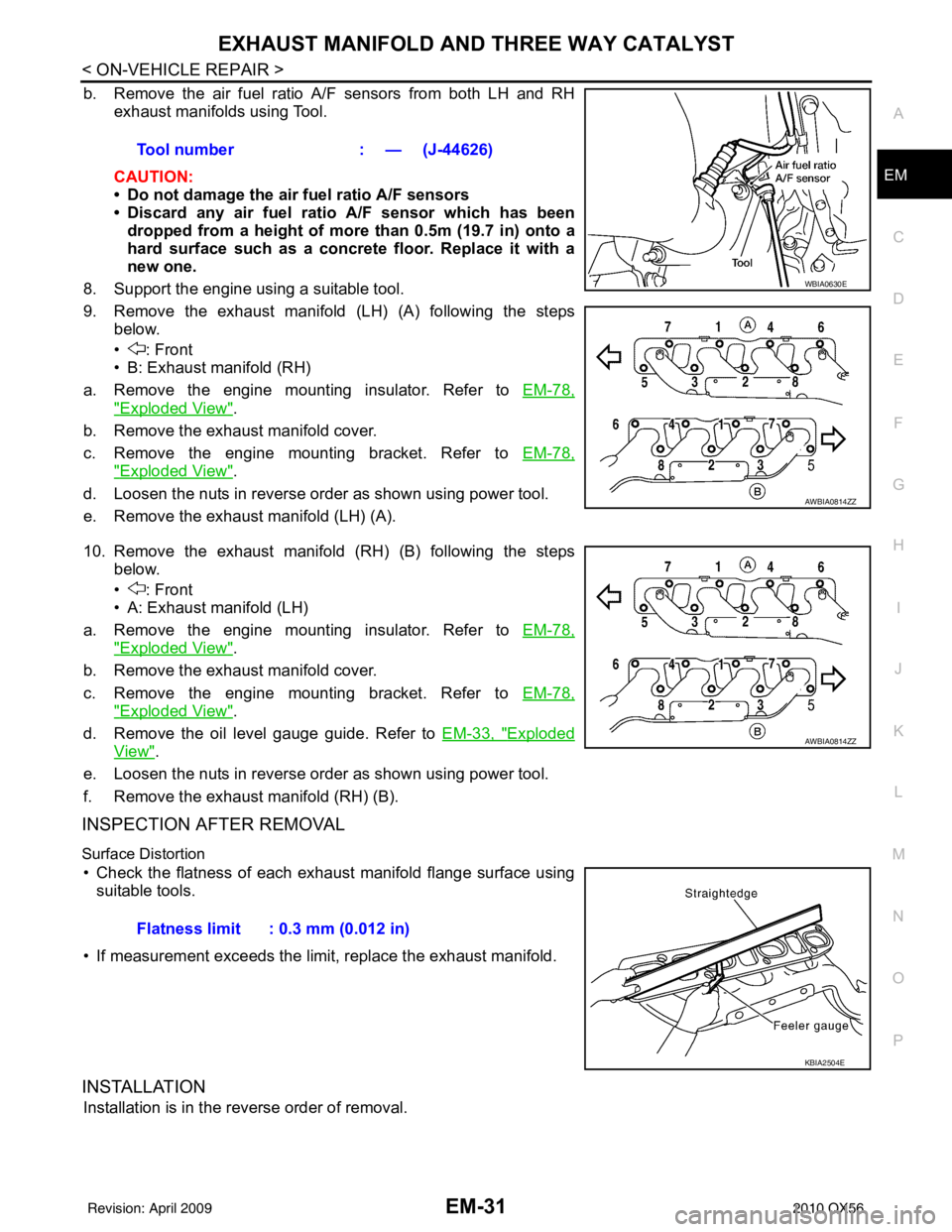
b. Remove the air fuel ratio A/F sensors from both LH and RH
exhaust manifolds using Tool.
CAUTION:
• Do not damage the air fuel ratio A/F sensors
• Discard any air fuel rati o A/F sensor which has been
dropped from a height of more than 0.5m (19.7 in) onto a
hard surface such as a concrete floor. Replace it with a
new one.
8. Support the engine using a suitable tool.
9. Remove the exhaust manifold (LH) (A) following the steps below.
• : Front
• B: Exhaust manifold (RH)
a. Remove the engine mounting insulator. Refer to EM-78,
"Exploded View".
b. Remove the exhaust manifold cover.
c. Remove the engine mounting bracket. Refer to EM-78,
"Exploded View".
d. Loosen the nuts in reverse order as shown using power tool.
e. Remove the exhaust manifold (LH) (A).
10. Remove the exhaust manifold (RH) (B) following the steps below.
• : Front
• A: Exhaust manifold (LH)
a. Remove the engine mounting insulator. Refer to EM-78,
"Exploded View".
b. Remove the exhaust manifold cover.
c. Remove the engine mounting bracket. Refer to EM-78,
"Exploded View".
d. Remove the oil level gauge guide. Refer to EM-33, "
Exploded
View".
e. Loosen the nuts in reverse order as shown using power tool.
f. Remove the exhaust manifold (RH) (B).
INSPECTION AFTER REMOVAL
Surface Distortion
• Check the flatness of each exhaust manifold flange surface using suitable tools.
• If measurement exceeds the limit, replace the exhaust manifold.
INSTALLATION
Installation is in the reverse order of removal. Tool number
: — (J-44626)
WBIA0630E
AWBIA0814ZZ
AWBIA0814ZZ
Flatness limit : 0.3 mm (0.012 in)
KBIA2504E
Revision: April 20092010 QX56
Page 1883 of 4210

EM-32
< ON-VEHICLE REPAIR >
EXHAUST MANIFOLD AND THREE WAY CATALYST
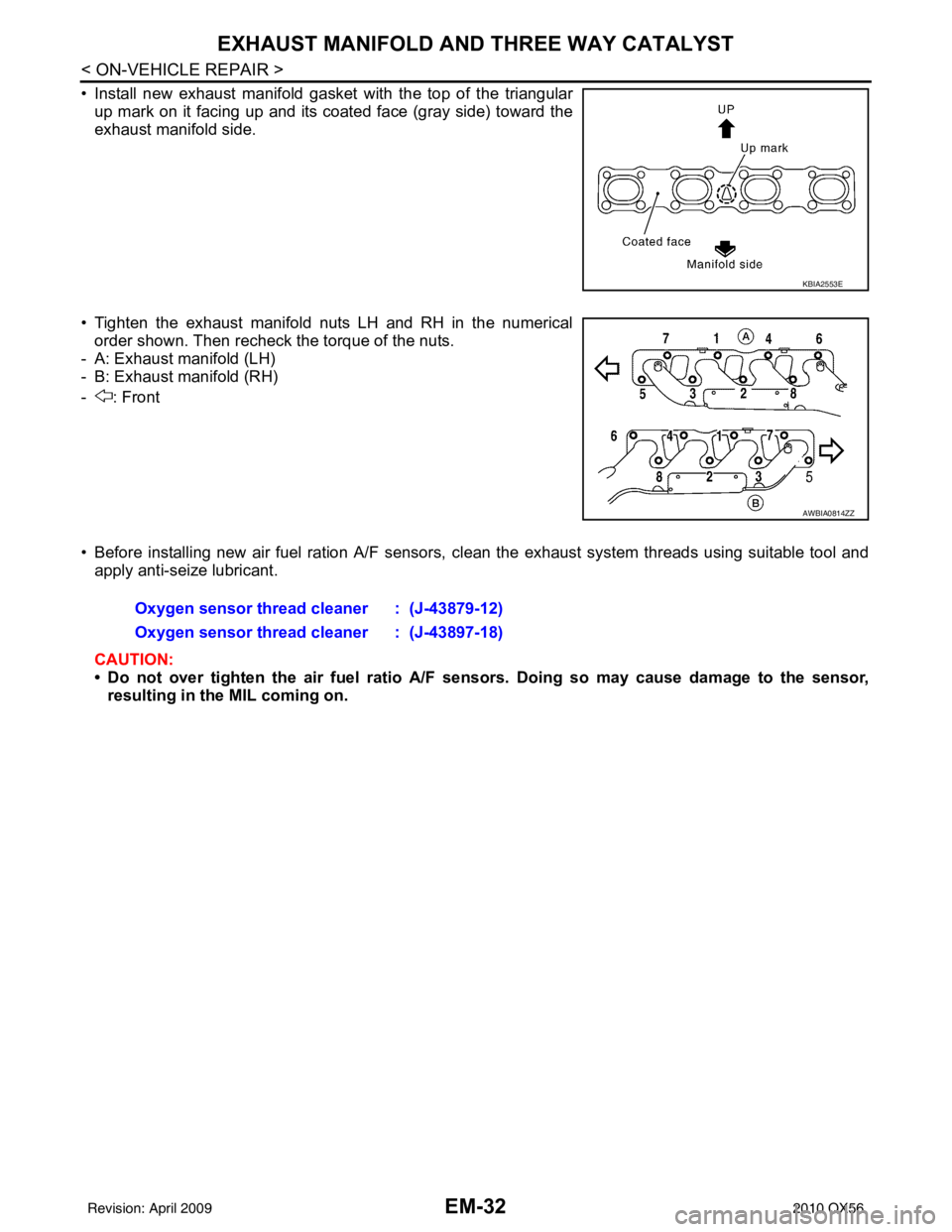
• Install new exhaust manifold gasket with the top of the triangularup mark on it facing up and its coated face (gray side) toward the
exhaust manifold side.
• Tighten the exhaust manifold nuts LH and RH in the numerical order shown. Then recheck the torque of the nuts.
- A: Exhaust manifold (LH)
- B: Exhaust manifold (RH)
- : Front
• Before installing new air fuel ration A/F sensors, clean the exhaust system threads using suitable tool and
apply anti-seize lubricant.
CAUTION:
• Do not over tighten the air fuel ratio A/F se nsors. Doing so may cause damage to the sensor,
resulting in the MIL coming on.
KBIA2553E
AWBIA0814ZZ
Oxygen sensor thread cleaner : (J-43879-12)
Oxygen sensor thread cleaner : (J-43897-18)
Revision: April 20092010 QX56
Page 1896 of 4210

TIMING CHAINEM-45
< ON-VEHICLE REPAIR >
C
DE
F
G H
I
J
K L
M A
EM
NP
O
Removal and InstallationINFOID:0000000005149000
NOTE:
• To remove timing chain and associated parts, start with those on the LH bank. The procedure for removing
parts on the RH bank is omitted because it is t he same as that for removal on the LH bank.
• To install timing chain and associated parts, start with those on the RH bank. The procedure for installing parts on the LH bank is omitted because it is t he same as that for installation on the RH bank.
REMOVAL
1. Remove the engine assembly from the vehicle. Refer to EM-78, "Removal and Installation".
2. Remove the following components and related parts: • Drive belt auto tensioner and idler pulley. Refer to EM-13, "
Removal and Installation".
• Thermostat housing and water hose. Refer to CO-22, "
Removal and Installation".
• Power steering oil pump bracket. Refer to ST-26, "
Removal and Installation".
• Oil pan (lower), (upper) and oil strainer. Refer to EM-33, "
Removal and Installation".
• Rocker cover. Refer to EM-38, "
Removal and Installation".
• Generator and generator bracket. Refer to CHG-21, "
Removal and Installation".
• Water pump. Refer to CO-20, "
Exploded View".
3. Disconnect and remove the camshaft position sensor.
4. Disconnect and remove the intake valve ti ming control position sensor (RH and LH).
5. Disconnect and remove the intake valve timing control solenoid valve (RH and LH).
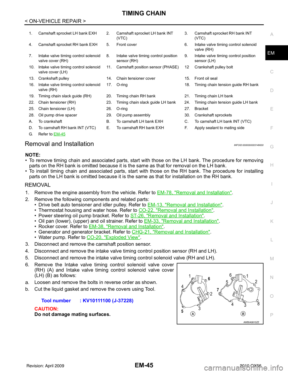
6. Remove the Intake valve timing control solenoid valve cover (RH) (A) and Intake valve timing control solenoid valve cover
(LH) (B) as follows:
a. Loosen and remove the bolts in reverse order as shown.
b. Cut the liquid gasket and remove the covers using Tool.
CAUTION:
Do not damage mating surfaces.
1. Camshaft sprocket LH bank EXH 2. Camshaft sprocket LH bank INT (VTC)3. Camshaft sprocket RH bank INT
(VTC)
4. Camshaft sprocket RH bank EXH 5. Front cover 6. Intake valve timing control solenoid
valve (RH)
7. Intake valve timing control solenoid valve cover (RH) 8. Intake valve timing control position
sensor (RH) 9. Intake valve timing control position
sensor (LH)
10. Intake valve timing control solenoid valve cover (LH) 11. Camshaft position
sensor (PHASE) 12 Cran kshaft pulley bolt
13. Crankshaft pulley 14. Chain tensioner cover 15. Front oil seal
16. Intake valve timing control solenoid valve (RH) 17. O-ring
18. Timing chain tension guide RH bank
19. Timing chain slack guide (RH) 20. Timing chain RH bank 21. Timing chain LH bank
22. Chain tensioner (RH) 23. Timing chain slack guide LH bank 24. Timing chain tension guide LH bank
25. Chain tensioner (LH) 26. O-ring 27. Bracket
28. Oil pump drive spacer 29. Oil pump assembly 30. Crankshaft sprockets
A. To crankshaft B. To camshaft LH bank EXH C. To camshaft LH bank INT (VTC)
D. To camshaft RH bank INT (VTC) E. To camshaft RH bank EXH F. Apply sealant to mating side
G. Refer to EM-45
Tool number : KV10111100 (J-37228)
AWBIA0815ZZ
Revision: April 20092010 QX56
Page 1904 of 4210

CAMSHAFTEM-53
< ON-VEHICLE REPAIR >
C
DE
F
G H
I
J
K L
M A
EM
NP
O
CAMSHAFT
Exploded ViewINFOID:0000000005149001
Removal and InstallationINFOID:0000000005149002
NOTE:
Do not remove the engine assembly to perform this procedure.
REMOVAL
1. Remove the power steering fluid reservoir tank bolts and position the power steering fluid reservoir tank
aside.
2. Remove the RH bank and LH bank rocker covers. Refer to EM-38, "
Removal and Installation".
3. Remove the spark plugs. Refer to EM-16, "
Removal and Installation".
4. Remove the drive belt. Refer to EM-13, "
Removal and Installation".
AWBIA0819GB
1. Cylinder head RH bank 2. Camshaft bracket (No. 2, 3, 4, 5) 3. Valve lifter
4. Camshaft bracket (No. 1) 5. Seal washer6. Camshaft RH bank EXH
7. Camshaft RH bank INT 8. Camshaft LH bank INT9. Camshaft LH bank EXH
10. Camshaft sprocket RH bank EXH 11. Camshaft sprocket RH bank INT (VTC)12. Camshaft sprocket LH bank INT
(VTC)
13. Camshaft sprocket LH bank EXH 14. Camshaft position sensor (PHASE) 15. O-ring
16. Cylinder head LH bank A. Refer to EM-53
Revision: April 20092010 QX56
Page 1905 of 4210

EM-54
< ON-VEHICLE REPAIR >
CAMSHAFT
5. Obtain compression TDC of No. 1 cylinder as follows:
a. Turn the crankshaft pulley clockwise to align the TDC identifica-tion notch (without paint mark) with the timing indicator on the
front cover.
b. At this time, make sure both intake and exhaust cam lobes of No. 1 cylinder (top front on LH bank) point outside.
• If they do not point outside, turn crankshaft pulley once more.
6. Disconnect and remove the camshaft position sensor. Refer to EM-44, "
Exploded View".
7. Disconnect and remove the intake valve timing c ontrol position sensor (RH and LH). Refer to EM-44,
"Exploded View".
8. Disconnect and remove the intake valve timing control solenoid valve (RH and LH). Refer to EM-44,
"Exploded View".
9. Remove the intake valve timing control solenoid cover RH bank (A) and intake valve timing control solenoid cover LH bank (B)
as follows:
a. Loosen and remove the bolts in reverse order as shown.
b. Cut the liquid gasket and remove the covers using Tool.
CAUTION:
Do not damage mating surfaces.
10. Paint alignment marks on the RH bank (A) timing chain links (C) and LH bank (B) timing chain links (D) and align with the cam-
shaft sprocket alignment marks (E) and (F).
11. Remove the chain tensioner (LH) using the following steps. WARNING:
Plunger, spring, and spring seat pop out when squeezing return-proof clip without holding
plunger head. It may cause serious injuries. Always hold plunger head when removing.
KBIA2476E
KBIA0400J
Tool number : KV10111100 (J-37228)
AWBIA0815ZZ
AWBIA0154ZZ
Revision: April 20092010 QX56
Page 1919 of 4210

EM-68
< ON-VEHICLE REPAIR >
CYLINDER HEAD
CYLINDER HEAD
Exploded ViewINFOID:0000000005149007
Removal and InstallationINFOID:0000000005149008
REMOVAL
1. Remove the engine assembly from the vehicle. Refer to EM-78, "Removal and Installation".
2. Remove the following components and related parts: • Drive belt auto tensioner drive belts and idler pulley. Refer to EM-14, "
Drive Belt Auto Tensioner and
Idler Pulley".
• Thermostat housing and hose. Refer to CO-22, "
Removal and Installation".
• Oil pan and oil strainer. Refer to EM-33, "
Removal and Installation".
• Fuel tube and fuel injector assembly. Refer to EM-40, "
Removal and Installation".
• Intake manifold. Refer to EM-26, "
Removal and Installation".
• Rocker cover. Refer to EM-38, "
Removal and Installation".
3. Remove the crankshaft pulley, front cover, oil pump, and timing chain. Refer to EM-45, "
Removal and
Installation".
4. Remove the camshaft sprockets and camshafts. Refer to EM-53, "
Removal and Installation".
5. Remove the cylinder head bolts in reverse of order shown.
6. Remove the cylinder heads.
INSPECTION AFTER REMOVAL
Cylinder Head Bolts Diameter
1. Harness bracket 2. Engine coolant temperature sensor 3. Washer
4. Cylinder head gasket (LH) 5. Cylinder head (RH) 6. Cylinder head bolt
7. Cylinder head gasket (RH) 8. Cylinder head (LH)
KBIA2528E
PBIC0068E
Revision: April 20092010 QX56
Page 1930 of 4210

ENGINE ASSEMBLYEM-79
< REMOVAL AND INSTALLATION >
C
DE
F
G H
I
J
K L
M A
EM
NP
O
1. Release the fuel pressure. Refer to
EC-489, "Fuel Pressure Check".
2. Drain the engine coolant. Refer to CO-11, "
Changing Engine Coolant".
3. Drain the engine oil. Refer to LU-9, "
Changing Engine Oil".
4. Partially drain the A/T fluid. Refer to TM-150, "
Changing the A/T Fluid (ATF)".
5. Disconnect the battery negative and positive terminal. Refer to PG-74, "
Removal and Installation".
6. Remove the engine hood. Refer to DLK-234, "
Removal and Installation of Hood Assembly".
7. Remove the cowl extension. Refer to EXT-18, "
Removal and Installation".
8. Remove the engine room cover using power tools.
9. Remove the air duct and air cleaner case assembly. Refer to EM-25, "
Removal and Installation".
10. Disconnect the vacuum hose between the vehicle and engine and set it aside.
11. Remove the radiator assembly and hoses. Refer to CO-15, "
Removal and Installation".
12. Remove the drive belt. Refer to EM-13, "
Removal and Installation".
13. Remove the fan blade. Refer to CO-18, "
Removal and Installation (Crankshaft Driven Type)".
14. Disconnect the engine room harness from the fuse box and set it aside.
15. Disconnect the ECM.
16. Disconnect the engine room harness from the engine side and set it aside.
17. Disconnect the engine harness grounds.
18. Disconnect the power steering reservoir t ank from the engine and move it aside.
19. Disconnect the power steering oil pump from the engine. Move it aside and secure it using suitable wire or rope. Refer to ST-26, "
Removal and Installation"
20. Remove the A/C compressor bolts and set the compressor aside. Refer to HA-31, "Removal and Installa-
tion for Compressor" (ATC).
21. Disconnect the brake booster vacuum line.
22. Disconnect the EVAP line.
23. Disconnect the fuel hose at the engine side connection. Refer to EM-40, "
Removal and Installation".
24. Disconnect the heater hoses at the cowl, and in stall plugs to avoid leakage of engine coolant.
25. Remove the A/T oil level indicator and indicator tube upper bolts.
26. Remove the front final drive assembly (4WD only). Refer to DLN-215, "
Removal and Installation".
27. Remove the exhaust manifolds. Refer to EM-30, "
Removal and Installation".
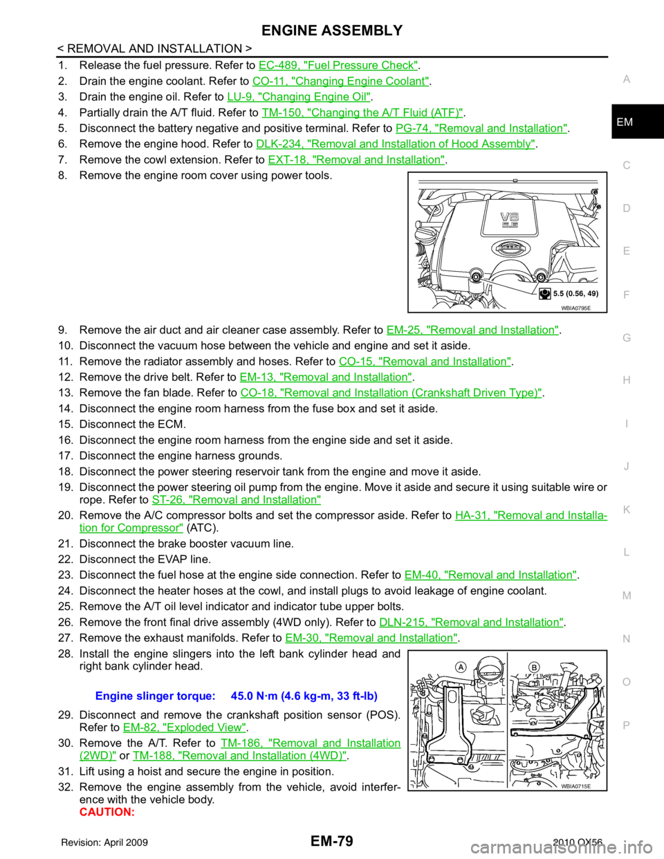
28. Install the engine slingers into the left bank cylinder head and right bank cylinder head.
29. Disconnect and remove the crankshaft position sensor (POS). Refer to EM-82, "
Exploded View".
30. Remove the A/T. Refer to TM-186, "
Removal and Installation
(2WD)" or TM-188, "Removal and Installation (4WD)".
31. Lift using a hoist and secure the engine in position.
32. Remove the engine assembly from the vehicle, avoid interfer- ence with the vehicle body.
CAUTION:
WBIA0795E
Engine slinger torque: 45.0 N·m (4.6 kg-m, 33 ft-lb)
WBIA0715E
Revision: April 20092010 QX56