clutch INFINITI QX56 2010 Factory Repair Manual
[x] Cancel search | Manufacturer: INFINITI, Model Year: 2010, Model line: QX56, Model: INFINITI QX56 2010Pages: 4210, PDF Size: 81.91 MB
Page 2324 of 4210

HA-32
< ON-VEHICLE REPAIR >
COMPRESSOR
• After recharging the A/C system with refrigerant, check for leaks.
Removal and Installation for Compressor ClutchINFOID:0000000005147654
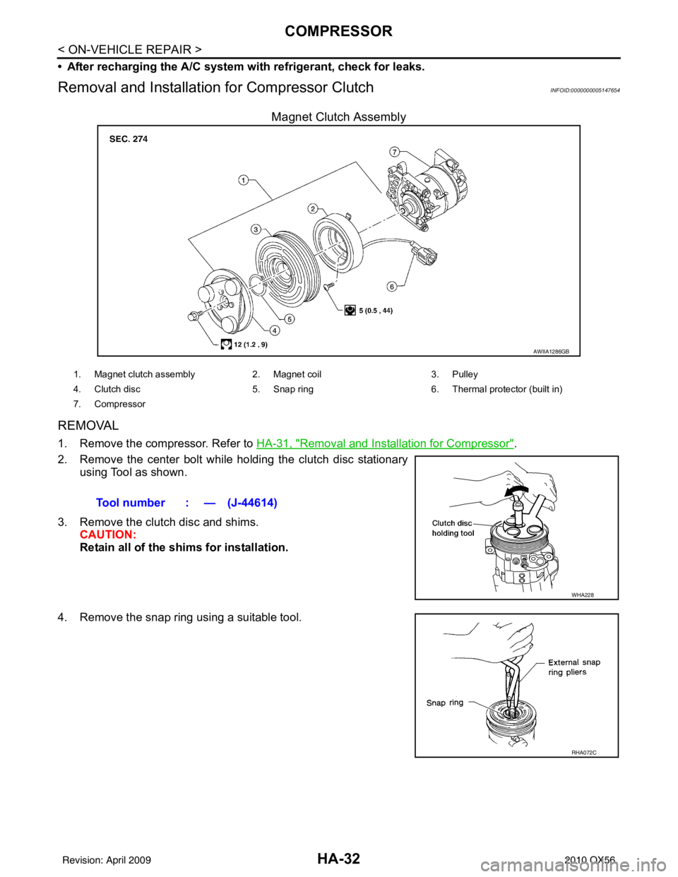
Magnet Clutch Assembly
REMOVAL
1. Remove the compressor. Refer to HA-31, "Removal and Installation for Compressor".
2. Remove the center bolt while holding the clutch disc stationary using Tool as shown.
3. Remove the clutch disc and shims. CAUTION:
Retain all of the shims for installation.
4. Remove the snap ring using a suitable tool.
AWIIA1286GB
1. Magnet clutch assembly 2. Magnet coil 3. Pulley
4. Clutch disc 5. Snap ring 6. Thermal protector (built in)
7. Compressor
Tool number : — (J-44614)
WHA228
RHA072C
Revision: April 20092010 QX56
Page 2325 of 4210

COMPRESSORHA-33
< ON-VEHICLE REPAIR >
C
DE
F
G H
J
K L
M A
B
HA
N
O P
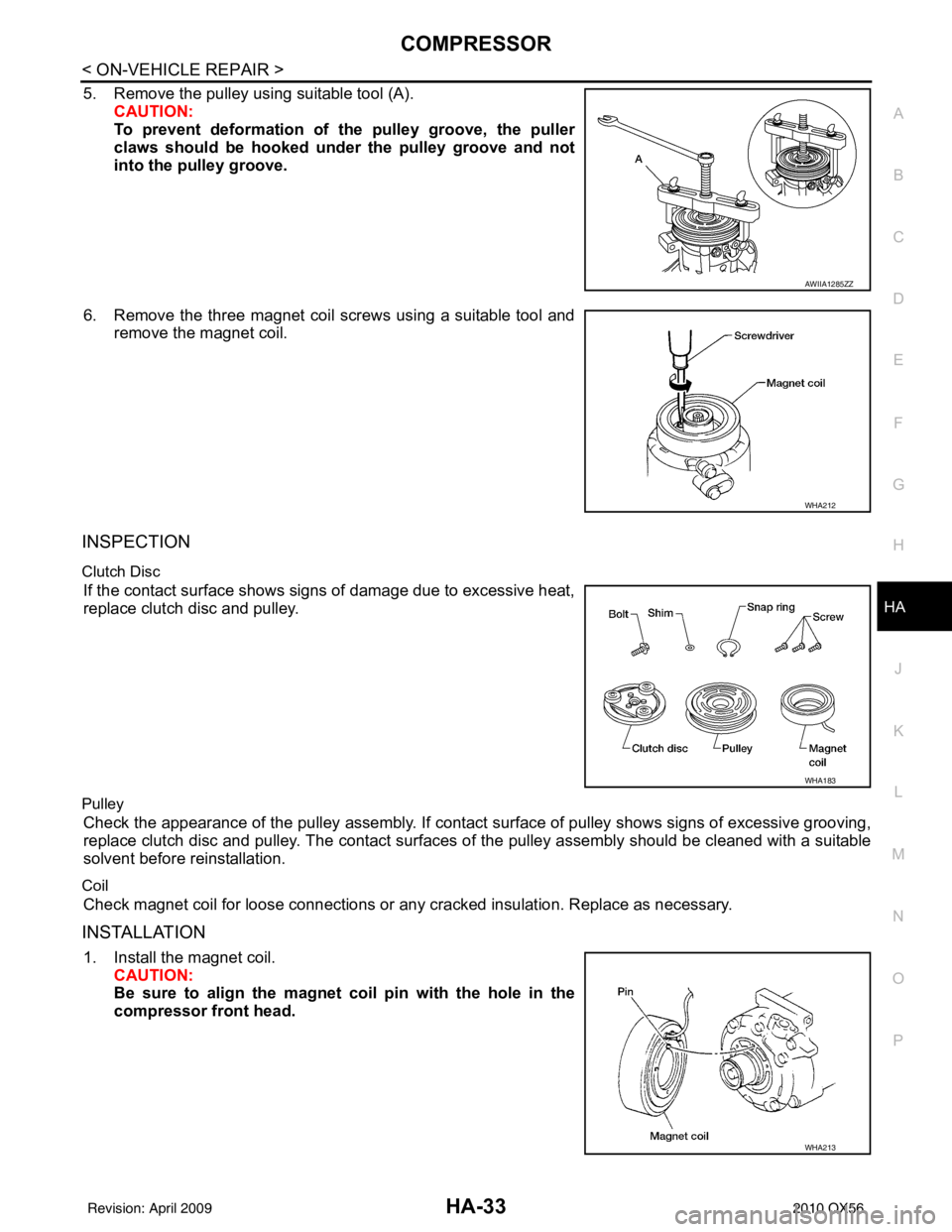
5. Remove the pulley using suitable tool (A). CAUTION:
To prevent deformation of the pulley groove, the puller
claws should be hooked un der the pulley groove and not
into the pulley groove.
6. Remove the three magnet coil screws using a suitable tool and remove the magnet coil.
INSPECTION
Clutch Disc
If the contact surface shows signs of damage due to excessive heat,
replace clutch disc and pulley.
Pulley
Check the appearance of the pulley assembly. If contact surface of pulley shows signs of excessive grooving,
replace clutch disc and pulley. The contact surfaces of the pulley assembly should be cleaned with a suitable
solvent before reinstallation.
Coil
Check magnet coil for loose connections or any cracked insulation. Replace as necessary.
INSTALLATION
1. Install the magnet coil. CAUTION:
Be sure to align the magnet coil pin with the hole in the
compressor front head.
AWIIA1285ZZ
WHA212
WHA183
WHA213
Revision: April 20092010 QX56
Page 2326 of 4210

HA-34
< ON-VEHICLE REPAIR >
COMPRESSOR
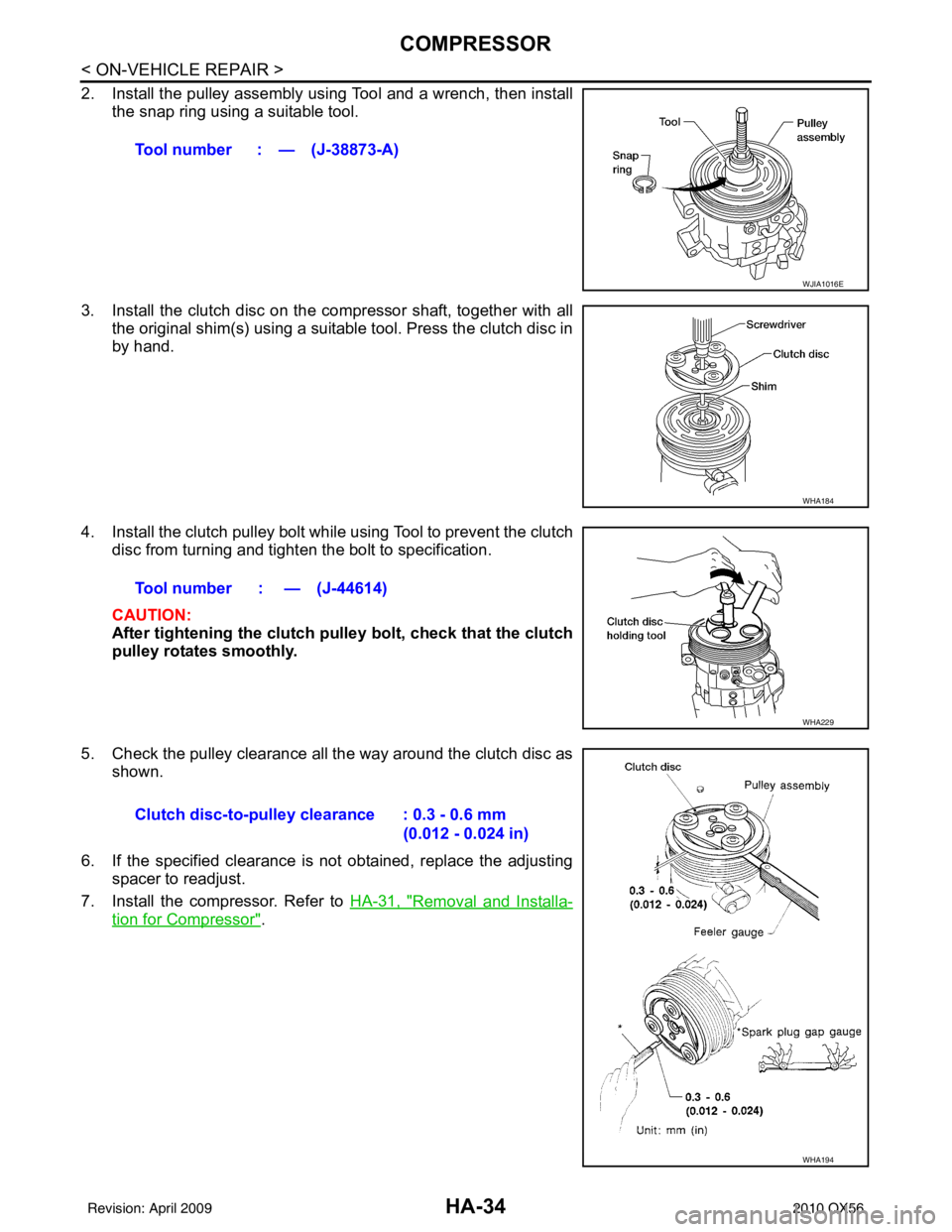
2. Install the pulley assembly using Tool and a wrench, then installthe snap ring using a suitable tool.
3. Install the clutch disc on the compressor shaft, together with all the original shim(s) using a suitabl e tool. Press the clutch disc in
by hand.
4. Install the clutch pulley bolt while using Tool to prevent the clutch
disc from turning and tighten the bolt to specification.
CAUTION:
After tightening the clutch pu lley bolt, check that the clutch
pulley rotates smoothly.
5. Check the pulley clearance all the way around the clutch disc as shown.
6. If the specified clearance is not obtained, replace the adjusting spacer to readjust.
7. Install the compressor. Refer to HA-31, "
Removal and Installa-
tion for Compressor".
Tool number : — (J-38873-A)
WJIA1016E
WHA184
Tool number : — (J-44614)
WHA229
Clutch disc-to-pulley clearance : 0.3 - 0.6 mm
(0.012 - 0.024 in)
WHA194
Revision: April 20092010 QX56
Page 2327 of 4210

COMPRESSORHA-35
< ON-VEHICLE REPAIR >
C
DE
F
G H
J
K L
M A
B
HA
N
O P
BREAK-IN OPERATION
When replacing compressor clutch assembly, always conduct the break-in operation. This is done by engag-
ing and disengaging the clutch about 30 times. Break-in operation raises the level of transmitted torque.
Revision: April 20092010 QX56
Page 2342 of 4210

HAC-2
Rear Air Control Component Function Check ........58
Air Mix Door Motor (Rear) Diagnosis Procedure ....59
Mode Door Motor (Rear) Diagnosis Procedure ......63
MAGNET CLUTCH ............................................68
System Description .............................................. ...68
Magnet Clutch Component Function Check ........ ...68
Magnet Clutch Diagnosis Procedure ................... ...68
WATER VALVE CIRCUIT ..................................73
Description ........................................................... ...73
Water Valve Diagnosis Procedure ..........................73
AMBIENT SENSOR ...........................................75
Component Description ....................................... ...75
Ambient Sensor Diagnosis Procedure ....................75
Ambient Sensor Component Inspection .................76
IN-VEHICLE SENSOR .......................................78
Component Description ....................................... ...78
In-Vehicle Sensor Diagnosis Procedure .................78
In-Vehicle Sensor Component Inspection ..............80
OPTICAL SENSOR ...........................................81
Component Description ..........................................81
Optical Sensor Diagnosis Procedure ......................81
INTAKE SENSOR ..............................................83
System Description .............................................. ...83
Intake Sensor Diagnosis Procedure .......................83
Intake Sensor Component Inspection ................. ...84
POWER SUPPLY AND GROUND CIRCUIT
FOR CONTROLLER ..........................................
86
Component Description ....................................... ...86
A/C Auto Amp. Component Function Check ..........86
A/C Auto Amp Power and Ground Diagnosis Pro-
cedure .................................................................. ...
87
ECU DIAGNOSIS .......................................89
AIR CONDITIONER CONTROL ..................... ...89
A/C Auto Amp. Terminals Reference Values ..........89
Wiring Diagram .................................................... ...91
SYMPTOM DIAGNOSIS ...........................107
AIR CONDITIONER CONTROL ..................... ..107
Symptom Matrix Chart ........................................ .107
INSUFFICIENT COOLING ................................108
Component Function Check ................................ .108
Diagnostic Work Flow ...........................................109
Performance Chart ................................................111
Trouble Diagnoses for Abnormal Pressure ...........112
INSUFFICIENT HEATING ................................116
Component Function Check .................................116
NOISE ...............................................................118
Component Function Check ................................ .118
MEMORY FUNCTION DOES NOT OPERATE ..120
Memory Function Check ...................................... .120
PRECAUTION ...........................................121
PRECAUTIONS .............................................. ..121
Precaution for Supplemental Restraint System
(SRS) "AIR BAG" and "SEAT BELT PRE-TEN-
SIONER" .............................................................. .
121
Working with HFC-134a (R-134a) ........................ .121
Precaution for Service Equipment ........................122
Revision: April 20092010 QX56
Page 2344 of 4210
![INFINITI QX56 2010 Factory Repair Manual HAC-4
< BASIC INSPECTION >[AUTOMATIC AIR CONDITIONER]
INSPECTION AND ADJUSTMENT
INSPECTION AND ADJUSTMENT
Operational Check (Front)INFOID:0000000005147669
The purpose of the operational check is to
c INFINITI QX56 2010 Factory Repair Manual HAC-4
< BASIC INSPECTION >[AUTOMATIC AIR CONDITIONER]
INSPECTION AND ADJUSTMENT
INSPECTION AND ADJUSTMENT
Operational Check (Front)INFOID:0000000005147669
The purpose of the operational check is to
c](/img/42/57032/w960_57032-2343.png)
HAC-4
< BASIC INSPECTION >[AUTOMATIC AIR CONDITIONER]
INSPECTION AND ADJUSTMENT
INSPECTION AND ADJUSTMENT
Operational Check (Front)INFOID:0000000005147669
The purpose of the operational check is to
confirm that the system operates properly.
CHECKING MEMORY FUNCTION
1. Set the temperature to 32 ° (90 °F).
2. Press the OFF switch.
3. Turn ignition switch OFF.
4. Turn ignition switch ON.
5. Press the AUTO switch.
6. Confirm that the set temperature remains at previous temperature.
7. Press the OFF switch.
If NG, go to trouble diagnosis procedure for HAC-120, "
Memory Function Check".
If OK, continue with next check.
CHECKING BLOWER
1. Press the blower speed control switch (+) once, blower should operate on low speed. The fan display should have one bar lit (on display).
2. Press the blower speed control switch (+) again, and continue checking blower speed and fan display until
all speeds are checked.
3. Leave blower on maximum speed.
If NG, go to trouble diagnosis procedure for HAC-48, "
Front Blower Motor Diagnosis Procedure".
If OK, continue with next check.
CHECKING DISCHARGE AIR
1. Press MODE switch four times and the DEF switch.
2. Each position indicator should change shape (on display).
3. Confirm that discharge air comes out according to the air distribution table. Refer to HAC-16, "
Discharge
Air Flow (Front)".
Mode door position is checked in the next step.
If NG, go to trouble diagnosis procedure for HAC-26, "
Mode Door Motor (Front) Diagnosis Procedure".
If OK, continue the check.
NOTE:
Confirm that the compressor clutch is engaged (sound or visual inspection) and intake door position is at
fresh when the DEF or D/F is selected.
CHECKING RECIRCULATION ( , ONLY)
1. Press recirculation ( ) switch one time. Recirculation indicator should illuminate.
2. Press recirculation ( ) switch one more time. Recirculation indicator should go off.
3. Listen for intake door position change (blower sound should change slightly).
If NG, go to trouble diagnosis procedure for HAC-40, "
Intake Door Motor Diagnosis Procedure".
If OK, continue the check.
NOTE:
Confirm that the compressor clutch is engaged (sound or vis ual inspection) and intake door position is at fresh
when the DEF or D/F is selected. REC ( ) is not allowed in DEF ( ) D/F ( ) or FOOT ( ).
CHECKING TEMPERATURE DECREASE
1. Rotate temperature control dial (drive or passenger) counterclockwise until 18° C (60°F) is displayed.
2. Check for cold air at appropriate discharge air outlets. Conditions : Engine running and at normal operating temperature
Revision: April 20092010 QX56
Page 2345 of 4210
![INFINITI QX56 2010 Factory Repair Manual INSPECTION AND ADJUSTMENTHAC-5
< BASIC INSPECTION > [AUTOMATIC AIR CONDITIONER]
C
D
E
F
G H
J
K L
M A
B
HAC
N
O P
If NG, listen for sound of air mix door motor operat ion. If OK, go to trouble diagnos INFINITI QX56 2010 Factory Repair Manual INSPECTION AND ADJUSTMENTHAC-5
< BASIC INSPECTION > [AUTOMATIC AIR CONDITIONER]
C
D
E
F
G H
J
K L
M A
B
HAC
N
O P
If NG, listen for sound of air mix door motor operat ion. If OK, go to trouble diagnos](/img/42/57032/w960_57032-2344.png)
INSPECTION AND ADJUSTMENTHAC-5
< BASIC INSPECTION > [AUTOMATIC AIR CONDITIONER]
C
D
E
F
G H
J
K L
M A
B
HAC
N
O P
If NG, listen for sound of air mix door motor operat ion. If OK, go to trouble diagnosis procedure for HAC-108,
"Component Function Check". If air mix door motor appears to be malfunctioning, go to HAC-31, "Air Mix Door
Motor (Driver) Component Function Check".
If OK, continue the check.
CHECKING TEMPERATURE INCREASE
1. Rotate temperature control dial clockwise (drive or passenger) until 32 °C (90° F) is displayed.
2. Check for hot air at appropriate discharge air outlets.
If NG, listen for sound of air mix door motor operat ion. If OK, go to trouble diagnosis procedure for HAC-116,
"Component Function Check". If air mix door motor appears to be malfunctioning, go to HAC-31, "Air Mix Door
Motor (Driver) Component Function Check".
If OK, continue with next check.
CHECK A/C SWITCH
1. Press A/C switch when AUTO switch is ON, or in manual mode.
2. A/C switch indicator will turn ON. • Confirm that the compressor clutch engages (sound or visual inspection).
NOTE:
If current mode setting is DEF or D/F, compre ssor clutch will already be engaged and cannot be turned off.
If NG, go to trouble diagnosis procedure for HAC-68, "
Magnet Clutch Diagnosis Procedure".
If OK, continue with next check.
CHECKING AUTO MODE
1. Press AUTO switch.
2. Display should indicate AUTO.
• If ambient temperature is warm, and selected temperat ure is cool, confirm that the compressor clutch
engages (sound or visual inspection). (Discharge air and blower speed will depend on ambient, in-vehi-
cle, and set temperatures.)
If NG, go to trouble diagnosis procedure for HAC-87, "
A/C Auto Amp Power and Ground Diagnosis Proce-
dure", then if necessary, trouble diagnosis procedure for HAC-68, "Magnet Clutch Diagnosis Procedure".
If all operational checks are OK (symptom cannot be duplicated), go to malfunction Simulation Tests in HAC-
3, "How to Perform Trouble Diagnosis For Quick And Accurate Repair" and perform tests as outlined to simu-
late driving conditions environment. If symptom appears. Refer to HAC-107, "
SymptomMatrixChart", and
perform applicable troubl e diagnosis procedures.
Operational Check (Rear)INFOID:0000000005147670
The purpose of the operational check is to confirm that the system operates properly.
CHECKING REAR BLOWER MOTOR
1. Turn the ignition switch ON.
2. Rotate rear air control (front) blower control dial to low speed.
3. Rotate the blower control dial clockwise and continue checking blower speed until all speeds are checked.
4. Leave blower on maximum speed.
5. Press the REAR CTRL switch from the rear air control (front).
6. Rotate rear air control (rear) blower control dial to low speed.
7. Rotate the blower control dial clockwise and continue checking blower speed until all speeds are checked.
8. Leave blower on maximum speed.
If NG, go to trouble diagnosis procedure for HAC-53, "
Rear Blower Motor Component Function Check".
If OK, continue with next check.
CHECKING REAR DISCHARGE AIR
Conditions : Engine running and at normal operating temperature
Revision: April 20092010 QX56
Page 2350 of 4210
![INFINITI QX56 2010 Factory Repair Manual HAC-10
< FUNCTION DIAGNOSIS >[AUTOMATIC AIR CONDITIONER]
FUNCTION INFORMATION
Defroster door motor is malfunctioning. Go to Trouble Diagnosis Procedure for Defroster Door Motor.
HAC-43
Front blower mo INFINITI QX56 2010 Factory Repair Manual HAC-10
< FUNCTION DIAGNOSIS >[AUTOMATIC AIR CONDITIONER]
FUNCTION INFORMATION
Defroster door motor is malfunctioning. Go to Trouble Diagnosis Procedure for Defroster Door Motor.
HAC-43
Front blower mo](/img/42/57032/w960_57032-2349.png)
HAC-10
< FUNCTION DIAGNOSIS >[AUTOMATIC AIR CONDITIONER]
FUNCTION INFORMATION
Defroster door motor is malfunctioning. Go to Trouble Diagnosis Procedure for Defroster Door Motor.
HAC-43
Front blower motor operation is malfunction-
ing.Go to Trouble Diagnosis Procedure for Front Blower Motor.
HAC-48
Rear blower motor operation is malfunction-
ing.Go to Trouble Diagnosis Procedure for Rear Blower Motor.
HAC-53
Rear air discharge outlet does not change. Go to Trouble Diagnosis Procedure for Mode Door Motor (rear). HAC-58
Rear air temperature does not change. Go to Trouble Diagnosis Procedure for Air Mix Door Motor (rear).HAC-58
Magnet clutch does not engage.Go to Trouble Diagnosis Procedure for Magnet Clutch. HAC-68
Insufficient coolingGo to Trouble Diagnosis Procedure for Insufficient Cooling. HAC-108
Insufficient heatingGo to Trouble Diagnosis Procedure for Insufficient Heating. HAC-116
NoiseGo to Trouble Diagnosis Procedure for Noise. HAC-118
Self-diagnosis cannot be performed. Go to Trouble Diagnosis Procedure for Self-diagnosis. HAC-86
Memory function does not operate.Go to Trouble Diagnosis Procedure for Memory Function. HAC-120
SymptomReference Page
Revision: April 20092010 QX56
Page 2351 of 4210
![INFINITI QX56 2010 Factory Repair Manual REFRIGERATION SYSTEMHAC-11
< FUNCTION DIAGNOSIS > [AUTOMATIC AIR CONDITIONER]
C
D
E
F
G H
J
K L
M A
B
HAC
N
O P
REFRIGERATION SYSTEM
Refrigerant CycleINFOID:0000000005197357
REFRIGERANT FLOW
The refri INFINITI QX56 2010 Factory Repair Manual REFRIGERATION SYSTEMHAC-11
< FUNCTION DIAGNOSIS > [AUTOMATIC AIR CONDITIONER]
C
D
E
F
G H
J
K L
M A
B
HAC
N
O P
REFRIGERATION SYSTEM
Refrigerant CycleINFOID:0000000005197357
REFRIGERANT FLOW
The refri](/img/42/57032/w960_57032-2350.png)
REFRIGERATION SYSTEMHAC-11
< FUNCTION DIAGNOSIS > [AUTOMATIC AIR CONDITIONER]
C
D
E
F
G H
J
K L
M A
B
HAC
N
O P
REFRIGERATION SYSTEM
Refrigerant CycleINFOID:0000000005197357
REFRIGERANT FLOW
The refrigerant flows in the standard pattern, that is, through the compressor, the condenser with liquid tank,
through the front and rear evaporators, and back to the compressor. The refrigerant evaporation through the
evaporator coils are controlled by front and rear externally equalized expansion valves, located inside the front
and rear evaporator cases.
Refrigerant System ProtectionINFOID:0000000005197358
REFRIGERANT PRESSURE SENSOR
The refrigerant system is protected against excessively hi gh or low pressures by the refrigerant pressure sen-
sor, located on the condenser. If the system pressure rises above or falls below the specifications, the refriger-
ant pressure sensor detects the pressure inside the refrigerant line and sends a voltage signal to the ECM.
The ECM de-energizes the A/C relay to disengage the magnetic compressor clutch when pressure on the high
pressure side detected by refrigerant pressu re sensor is over about 2,746 kPa (28 kg/cm
2, 398 psi), or below
about 120 kPa (1.22 kg/cm
2, 17.4 psi).
WJIA1342E
Revision: April 20092010 QX56
Page 2355 of 4210
![INFINITI QX56 2010 Factory Repair Manual AUTOMATIC AIR CONDITIONER SYSTEMHAC-15
< FUNCTION DIAGNOSIS > [AUTOMATIC AIR CONDITIONER]
C
D
E
F
G H
J
K L
M A
B
HAC
N
O P
Rear Air Controls
REAR TEMPERATURE CONTROL DIAL (FRONT/REAR)
The temperature INFINITI QX56 2010 Factory Repair Manual AUTOMATIC AIR CONDITIONER SYSTEMHAC-15
< FUNCTION DIAGNOSIS > [AUTOMATIC AIR CONDITIONER]
C
D
E
F
G H
J
K L
M A
B
HAC
N
O P
Rear Air Controls
REAR TEMPERATURE CONTROL DIAL (FRONT/REAR)
The temperature](/img/42/57032/w960_57032-2354.png)
AUTOMATIC AIR CONDITIONER SYSTEMHAC-15
< FUNCTION DIAGNOSIS > [AUTOMATIC AIR CONDITIONER]
C
D
E
F
G H
J
K L
M A
B
HAC
N
O P
Rear Air Controls
REAR TEMPERATURE CONTROL DIAL (FRONT/REAR)
The temperature increases or dec reases the set temperature.
REAR MODE SWITCHES (FRONT/REAR)
Controls the air discharge outlets.
REAR BLOWER CONTROL DIAL (FRONT)
When the REAR CTRL switch is in the off (indicator off) the rear air control (front) controls the rear blower
motor speed regardless of the rear air control (rear) blow er control dial (rear) position. The rear air control
(front) controls the blower motor speed.
REAR BLOWER CONTROL DIAL (REAR)
When the REAR CTRL switch is in the on (indicator on) the rear air control (rear) controls the rear blower
motor speed regardless of the rear air control (front) blow er control dial (front) position. The rear air control
(rear) controls the blower motor speed.
MAGNET CLUTCH CONTROL
When A/C switch or DEF switch is pressed, A/ C auto amp. inputs compressor ON signal to BCM.
BCM sends compressor ON signal to ECM and A/C auto amp., via CAN communication line.
ECM judges whether compressor can be turned ON, based on each sensor status (refrigerant pressure sen-
sor signal, throttle angle sensor, etc.). If it judges compressor can be turned ON, it sends compressor ON sig-
nal to IPDM E/R, via CAN communication line.
AWIIA0082ZZ
1. Rear air control (front )2. Rear air control (rear)
AWIIA1069GB
Revision: April 20092010 QX56