ECU INFINITI QX56 2010 Factory Service Manual
[x] Cancel search | Manufacturer: INFINITI, Model Year: 2010, Model line: QX56, Model: INFINITI QX56 2010Pages: 4210, PDF Size: 81.91 MB
Page 3850 of 4210

STALL TESTTM-155
< ON-VEHICLE MAINTENANCE >
CEF
G H
I
J
K L
M A
B
TM
N
O P
STALL TEST
Inspection and JudgmentINFOID:0000000005148726
A/T FLUID CHECK
Fluid Leakage and Fluid Level Check
• Inspect for fluid leakage and check the fluid level. Refer to TM-148, "Checking the A/T Fluid (ATF)".
Fluid Condition Check
Inspect the fluid condition.
STALL TEST
Stall Test Procedure
1. Inspect the amount of engine oil. Replenish the engine oil if necessary.
2. Drive for about 10 minutes to warm up the vehicle so that the A/
T fluid temperature is 50 to 80 °C (122 to 176 °F). Inspect the
amount of ATF. Replenish if necessary.
3. Securely engage the parking brake so that the tires do not turn.
Fluid condition Conceivable Cause Required Operation
Varnished (viscous
varnish state) Clutch, brake
scorchedReplace the ATF and check the A/T
main unit and the vehicle for mal-
functions (wire harnesses, cooler
pipes, etc.)
Milky white or
cloudy Water in the fluidReplace the ATF and check for plac-
es where water is getting in.
Large amount of
metal powder mixed
in Unusual wear of
sliding parts within
A/T
Replace the ATF and check for im-
proper operation of the A/T.
SAT638A
SAT647B
SCIA1224E
Revision: April 20092010 QX56
Page 3852 of 4210

LINE PRESSURE TESTTM-157
< ON-VEHICLE MAINTENANCE >
CEF
G H
I
J
K L
M A
B
TM
N
O P
LINE PRESSURE TEST
Inspection and JudgmentINFOID:0000000005148727
LINE PRESSURE TEST
Line Pressure Test Port
Line Pressure Test Procedure
1. Inspect the amount of engine oil and replenish if necessary.
2. Drive the car for about 10 minutes to warm it up so that the ATF reaches in range of 50 to 80 °C (122 to
176° F), then inspect the amount of ATF and replenish if necessary.
NOTE:
The automatic fluid temperature rises in range of 50 to 80 °C (122 to 176° F) during 10 minutes of
driving.
3. After warming up remove the oil pressure detection plug and install the Tool.
CAUTION:
When using the oil pressure ga uge, be sure to use the O-
ring attached to the oil pressure detection plug.
4. Securely engage the parking brake so that the tires do not turn.
SCIA2187E
SCIA5309E
SCIA1224E
Revision: April 20092010 QX56
Page 3861 of 4210

TM-166
< ON-VEHICLE REPAIR >
AIR BREATHER HOSE
AIR BREATHER HOSE
Removal and InstallationINFOID:0000000005402587
REMOVAL and INSTALLATION
2WD
CAUTION:
• Install air breather hose with paint mark at upper side.
• When installing the air breather hose, do not crush or block by folding or bending the hose.
• When inserting the hose to the tran smission tube, be sure to insert it fully until its end reaches the
tube bend portion.
• Make sure clip is securely installed to bracket.
REMOVAL
AWDIA0554GB
A. Set air breather hose with
paint mark at upper side B. Clip (set securely to bracket)
Revision: April 20092010 QX56
Page 3873 of 4210

TM-178
< ON-VEHICLE REPAIR >
CONTROL VALVE WITH TCM
i. Install new O-ring (1) in plug (2).CAUTION:
• Do not reuse O-ring.
• Apply ATF to O-ring.
• O-ring should be free of contamination.
ii. Install plug (2) to bracket (1).
iii. Install plug (1) [with bracket (2)] to control valve with TCM. Tighten plug bolt ( ) to the specified torque.
CAUTION:
Adjust bolt hole of bracket to bolt hole of control valve with
TCM.
6. Install control valve with TCM in transmission case. CAUTION:
• Make sure that input speed sensor is securely installedinto input speed sensor hole (A).
• Hang down output speed sen sor harness toward outside
so as not to disturb installati on of control valve with TCM.
• Adjust A/T assembly harness co nnector of control valve
with TCM to terminal hole of transmission case.
• Assemble it so that manual valve cutout is engaged with manual plate projection.
JSDIA1313ZZ
JSDIA1312ZZ
JSDIA1311ZZ
1 : Brake band
JSDIA1318ZZ
SCIA5142E
Revision: April 20092010 QX56
Page 3874 of 4210

CONTROL VALVE WITH TCMTM-179
< ON-VEHICLE REPAIR >
CEF
G H
I
J
K L
M A
B
TM
N
O P
7. Install bolts (A), (B) and (C) in control valve with TCM. • : Front
8. Tighten bolt (1), (2) and (3) temporarily to prevent dislocation. After that tighten them in order (1 → 2 → 3). Then tighten other
bolts.
• : Front
9. Tighten control valve with TCM bolts to the specified torque.
10. After installing the A/T fluid temperature sensor 2, connect the A/T fluid temperature sensor 2 connector
as shown below.
a. Connect A/T fluid temperature sensor 2 connector (A).
b. Securely fasten terminal cord assembly and A/T fluid tempera- ture sensor 2 harness with terminal clips ( ).
11. Connect output speed sensor connector (1).
Bolt symbol Length mm (in) Number of bolts
A 42 (1.65) 5
B 55 (2.17) 6
C 40 (1.57) 1
SCIA8074E
Bolt symbolAB C
Number of bolts 56 1
Length mm (in) 42 (1.65) 55 (2.17)40 (1.57)
Tightening torque
N·m (km-g, in-lb) 7.9 (0.81, 70)With ATF applied
7.9 (0.81, 70)
SCIA8075E
SCIA8124E
JSDIA1319ZZ
Revision: April 20092010 QX56
Page 3875 of 4210

TM-180
< ON-VEHICLE REPAIR >
CONTROL VALVE WITH TCM
12. Securely fasten output speed sensor (1) harness with terminalclip ( ).
13. Install oil pan to transmission case. Refer to TM-170, "
Oil Pan".
14. Pull up A/T assembly harness connector. CAUTION:
Do not damage connector.
15. Install snap ring to A/T assembly harness connector.
16. Connect A/T assembly harness connector.
17. Connect the negative battery terminal.
18. Refill the A/T with fluid and check the fluid level and for fluid leakage. Refer to TM-148, "
Checking the A/T Fluid (ATF)".
REMOVAL AND INSTALLATION OF A/T FLUID TEMPERATURE SENSOR 2
Removal
1. Disconnect negative battery terminal.
2. Remove oil pan and oil pan gasket. Refer to TM-170, "
Oil Pan".
3. Disconnect A/T fluid temperat ure sensor 2 connector (A).
CAUTION:
Do not damage connector.
4. Straighten terminal clip ( ) to free A/T fluid temperature sensor 2 harness.
JSDIA1316ZZ
SCIA5038E
SCIA5039E
SCIA8125E
Revision: April 20092010 QX56
Page 3877 of 4210

TM-182
< ON-VEHICLE REPAIR >
CONTROL VALVE WITH TCM
3. Connect A/T fluid temperature sensor 2 connector (A).
4. Securely fasten A/T fluid temperature sensor 2 harness with ter-minal clip .
5. Install oil pan to transmission case. Refer to TM-170, "
Oil Pan".
6. Connect the negative battery terminal.
7. Refill the A/T with fluid and check the fluid level and for fluid leakage. Refer to TM-148, "
Checking the A/T
Fluid (ATF)".
REMOVAL AND INSTALLATION OF PLUG
Removal
1. Disconnect negative battery terminal.
2. Remove oil pan and oil pan gasket. Refer to TM-170, "
Oil Pan".
3. Remove plug (1) with bracket (2) from control valve with TCM.
4. Remove bracket (1) from plug (2).
5. Remove O-ring (1) from plug (2).
Installation
CAUTION:
SCIA8125E
: Bolt
JSDIA1311ZZ
JSDIA1312ZZ
JSDIA1313ZZ
Revision: April 20092010 QX56
Page 3882 of 4210

TRANSMISSION ASSEMBLYTM-187
< REMOVAL AND INSTALLATION >
CEF
G H
I
J
K L
M A
B
TM
N
O P
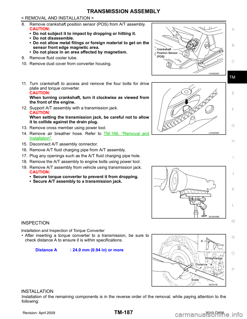
8. Remove crankshaft position sens or (POS) from A/T assembly.
CAUTION:
• Do not subject it to impact by dropping or hitting it.
• Do not disassemble.
• Do not allow metal filings or foreign material to get on the
sensor front edge magnetic area.
• Do not place in an area affected by magnetism.
9. Remove fluid cooler tube.
10. Remove dust cover from converter housing.
11. Turn crankshaft to access and remove the four bolts for drive plate and torque converter.
CAUTION:
When turning crankshaft, turn it clockwise as viewed from
the front of the engine.
12. Support A/T assembly with a transmission jack. CAUTION:
When setting the transmission jack, be careful not to allow
it to collide agai nst the drain plug.
13. Remove cross member using power tool.
14. Remove air breather hose. Refer to TM-166, "
Removal and
Installation".
15. Disconnect A/T assembly connector.
16. Remove A/T fluid charging pipe from A/T assembly.
17. Plug any openings such as the A/T fluid charging pipe hole.
18. Remove the A/T assembly to engine bolts using power tool.
19. Remove A/T assembly from vehicle using transmission jack. CAUTION:
• Secure torque converter to prevent it from dropping.
• Secure A/T assembly to a transmission jack.
INSPECTION
Installation and Inspection of Torque Converter
• After inserting a torque converter to a transmission, be sure to check distance A to ensure it is within specifications.
INSTALLATION
Installation of the remaining components is in the revers e order of the removal, while paying attention to the
following:
LCIA0334E
LCIA0335E
SCIA0499E
Distance A : 24.0 mm (0.94 in) or more
SAT017B
Revision: April 20092010 QX56
Page 3883 of 4210

TM-188
< REMOVAL AND INSTALLATION >
TRANSMISSION ASSEMBLY
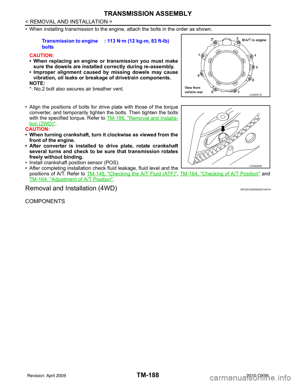
• When installing transmission to the engine, attach the bolts in the order as shown.CAUTION:
• When replacing an engine or transmission you must make
sure the dowels are installe d correctly during re-assembly.
• Improper alignment caused by missing dowels may cause
vibration, oil leaks or breakage of drivetrain components.
NOTE:
*: No.2 bolt also secures air breather vent.
• Align the positions of bolts for drive plate with those of the torque converter, and temporarily tighten the bolts. Then tighten the bolts
with the specified torque. Refer to TM-186, "
Removal and Installa-
tion (2WD)".
CAUTION:
• When turning crankshaft, turn it clockwise as viewed from the front of the engine.
• After converter is installed to drive plate, rotate crankshaft
several turns and check to be sure that transmission rotates
freely without binding.
• Install crankshaft pos ition sensor (POS).
• After completing installation check fluid leakage, fluid level and the
positions of A/T. Refer to TM-148, "
Checking the A/T Fluid (ATF)", TM-164, "Checking of A/T Position" and
TM-164, "
Adjustment of A/T Position".
Removal and Installation (4WD)INFOID:0000000005148744
COMPONENTS
Transmission to engine
bolts : 113 N·m (12 kg-m, 83 ft-lb)
LCIA0371E
LCIA0335E
Revision: April 20092010 QX56
Page 3885 of 4210

TM-190
< REMOVAL AND INSTALLATION >
TRANSMISSION ASSEMBLY
8. Remove crankshaft position sensor (POS) from A/T assembly.CAUTION:
• Do not subject it to impact by dropping or hitting it.
• Do not disassemble.
• Do not allow metal filings or fo reign material to get on the
sensor front edge magnetic area.
• Do not place in an area affected by magnetism.
9. Remove A/T fluid cooler tube from A/T assembly.
10. Remove dust cover from converter housing.
11. Turn crankshaft, and remove the four bolts for drive plate and torque converter.
CAUTION:
When turning crankshaft, turn it clockwise as viewed from
the front of the engine.
12. Support A/T assembly using transmission jack and Tool. CAUTION:
When setting the transmission jack, be careful not to allow it to collide against the drain plug.
NOTE:
The actual special service tool may differ from tool shown.
13. Remove cross member using power tool.
14. Tilt the transmission slightly to keep the cl earance between body and transmission, then disconnect air
breather hose from A/T fluid charging pipe.
15. Remove air breather hose. Refer to TM-166, "
Removal and Installation".
16. Disconnect A/T assembly connector and transfer unit connector.
17. Remove A/T fluid charging pipe.
18. Plug any openings such as the fluid charging pipe hole.
19. Remove A/T assembly to engine bolts using power tool.
20. Remove A/T assembly with transfer from vehicle. CAUTION:
• Secure torque converter to prevent it from dropping.
• Secure A/T assembly to transmission jack.
21. Remove transfer from A/T assembly. Refer to TM-188,
"Removal and Installation (4WD)".
INSPECTION
Installation and Inspection of Torque Converter
LCIA0334E
LCIA0335E
Tool number : — (J-47002)
SCIA2203E
Revision: April 20092010 QX56