oil level INFINITI QX56 2010 Factory Service Manual
[x] Cancel search | Manufacturer: INFINITI, Model Year: 2010, Model line: QX56, Model: INFINITI QX56 2010Pages: 4210, PDF Size: 81.91 MB
Page 6 of 4210

2010
QUICK REFERENCE CHART: QX56
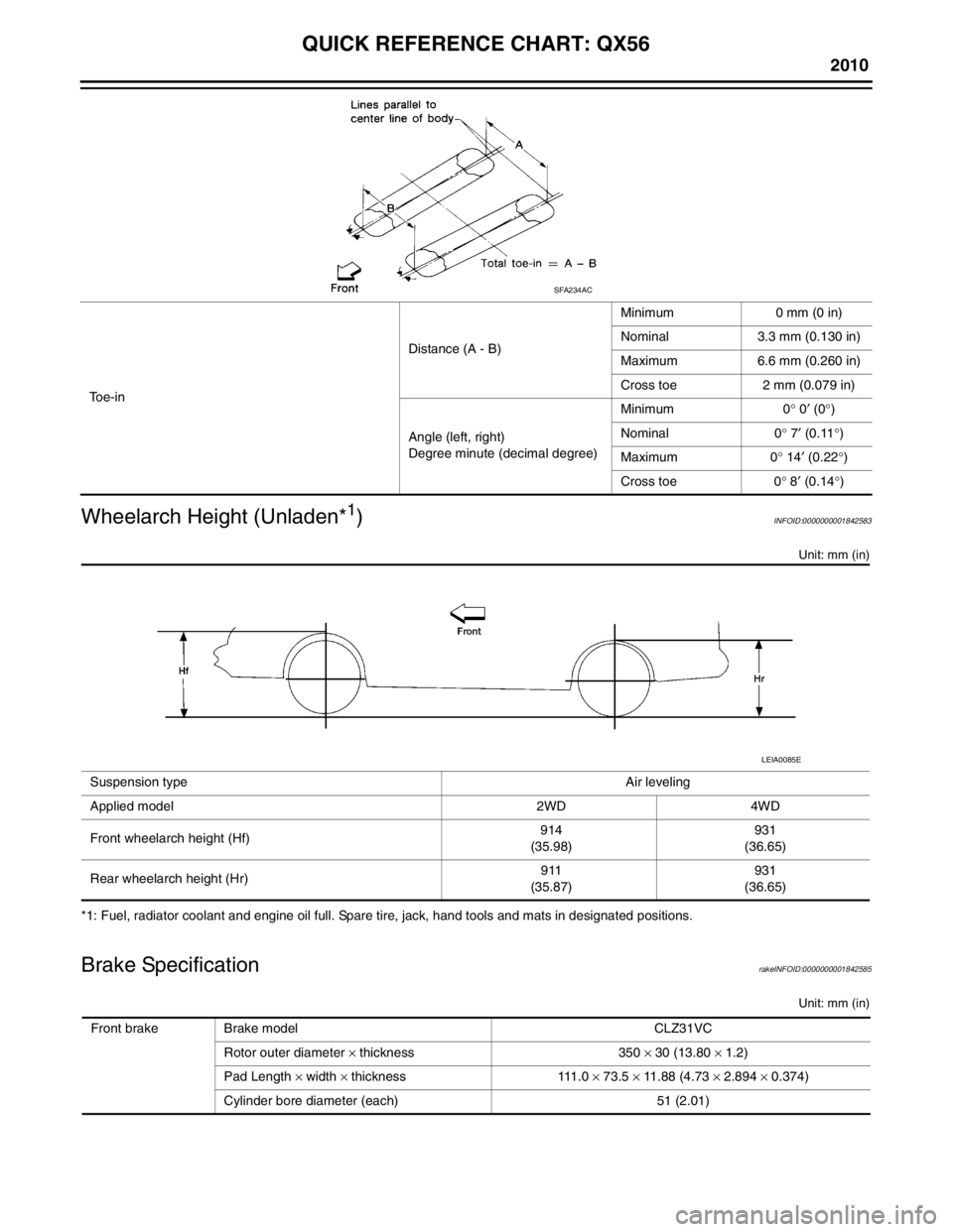
Wheelarch Height (Unladen*
1)INFOID:0000000001842583
Unit: mm (in)
*1: Fuel, radiator coolant and engine oil full. Spare tire, jack, hand tools and mats in designated positions.
Brake SpecificationrakeINFOID:0000000001842585
Unit: mm (in)
To e - i n Distance (A - B)
Minimum 0 mm (0 in)
Nominal 3.3 mm (0.130 in)
Maximum 6.6 mm (0.260 in)
Cross toe 2 mm (0.079 in)
Angle (left, right)
Degree minute (decimal degree) Minimum 0
° 0 ′ (0 °)
Nominal 0 ° 7 ′ (0.11 °)
Maximum 0 ° 14 ′ (0.22 °)
Cross toe 0 ° 8 ′ (0.14 °)
SFA234AC
Suspension type Air leveling
Applied model 2WD 4WD
Front wheelarch height (Hf) 914
(35.98) 931
(36.65)
Rear wheelarch height (Hr) 911
(35.87) 931
(36.65)
LEIA0085E
Front brake Brake model CLZ31VC
Rotor outer diameter × thickness 350 × 30 (13.80 × 1.2)
Pad Length × width × thickness 111.0 × 73.5 × 11.88 (4.73 × 2.894 × 0.374)
Cylinder bore diameter (each) 51 (2.01)
Page 8 of 4210

2010
QUICK REFERENCE CHART: QX56
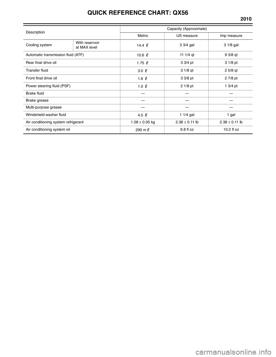
Cooling systemWith reservoir
at MAX level
14.4
3 3/4 gal 3 1/8 gal
Automatic transmission fluid (ATF) 10.6 11 1/4 qt 9 3/8 qt
Rear final drive oil 1.75 3 3/4 pt 3 1/8 pt
Transfer fluid 3.0 3 1/8 qt 2 5/8 qt
Front final drive oil 1.6 3 3/8 pt 2 7/8 pt
Power steering fluid (PSF) 1.0 2 1/8 pt 1 3/4 pt
Brake fluid — — —
Brake grease — — —
Multi-purpose grease — — —
Windshield washer fluid 4.5 1 1/4 gal 1 gal
Air conditioning system refrigerant 1.08 ± 0.05 kg 2.38 ± 0.11 lb 2.38 ± 0.11 lb
Air conditioning system oil 290 m9.8 fl oz 10.2 fl oz
Description
Capacity (Approximate)
Metric US measure Imp measure
Page 482 of 4210

BRAKE MASTER CYLINDERBR-37
< DISASSEMBLY AND ASSEMBLY >
C
DE
G H
I
J
K L
M A
B
BR
N
O P
DISASSEMBLY AND ASSEMBLY
BRAKE MASTER CYLINDER
Disassembly and AssemblyINFOID:0000000005147922
DISASSEMBLY
CAUTION:
• Master cylinder assembly cannot be disassembled.
• Do not drop parts. If a part is dropped, do not use it.
1. Pull the reservoir tank off the master cylinder assembly.
2. Remove the grommets from master cylinder assembly and discard the grommets. CAUTION:
Discard the grommets, do not reuse.
3. Remove the fluid level sensor from the reservoir tank.
4. Remove the front and rear pressure sensors and discard. CAUTION:
Discard the front and rear pressure sensors, do not reuse.
ASSEMBLY
CAUTION:
• Never use mineral oil such as kerosene, g asoline during the cleaning and assembly process.
• Do not drop parts. If a part is dropped, do not use it.
1. Reservoir cap 2. Fluid level sensor 3. Grommet
4. Master cylinder assembly 5. Front pressure sensor6. Rear pressure sensor
7. Seal 8. Reservoir tankB. Brake fluid
R. Rubber grease
AWFIA0415GB
Revision: April 20092010 QX56
Page 603 of 4210
![INFINITI QX56 2010 Factory Service Manual PRECAUTIONSBRC-111
< PRECAUTION > [VDC/TCS/ABS]
C
D
E
G H
I
J
K L
M A
B
BRC
N
O P
5. When the repair work is completed, return the ignition switch to the ″LOCK ″ position before connecting
the ba INFINITI QX56 2010 Factory Service Manual PRECAUTIONSBRC-111
< PRECAUTION > [VDC/TCS/ABS]
C
D
E
G H
I
J
K L
M A
B
BRC
N
O P
5. When the repair work is completed, return the ignition switch to the ″LOCK ″ position before connecting
the ba](/img/42/57032/w960_57032-602.png)
PRECAUTIONSBRC-111
< PRECAUTION > [VDC/TCS/ABS]
C
D
E
G H
I
J
K L
M A
B
BRC
N
O P
5. When the repair work is completed, return the ignition switch to the ″LOCK ″ position before connecting
the battery cables. (At this time, the steering lock mechanism will engage.)
6. Perform a self-diagnosis check of al l control units using CONSULT-III.
Precaution for Brake SystemINFOID:0000000005148094
CAUTION:
• Always use recommended brake fluid. Refer to MA-13, "
Fluids and Lubricants".
• Never reuse drained brake fluid.
• Be careful not to splash brake fluid on painted areas; it may cause paint damage. If brake fluid is
splashed on painted areas, wash it away with water immediately.
• To clean or wash all parts of master cylin der and disc brake caliper, use clean brake fluid.
• Never use mineral oils such as gasoline or kerosen e. They will ruin rubber parts of the hydraulic sys-
tem.
• Use flare nut wrench when removing and installing brake
tube.
• If a brake fluid leak is found, the part must be disassembled
without fail. Then it has to be replaced with a new one if a
defect exists.
• Turn the ignition switch OFF and remove the connector of the ABS actuator and electric unit (con trol unit) or the battery ter-
minal before performing the work.
• Always torque brake lines when installing.
• Burnish the brake contact surf aces after refinishing or replac-
ing rotors, after replacing pads, or if a soft pedal occurs at
very low mileage.
Refer to BR-30, "
Brake Burnishing Procedure" (front disc brake) or BR-35, "Brake Burnishing Proce-
dure" (rear disc brake).
WARNING:
• Clean brake pads and shoes with a waste cl oth, then wipe with a dust collector.
Precaution for Brake ControlINFOID:0000000005148095
• During ABS operation, the brake pedal may vibrate lightly and a mechanical noise may be heard. This is
normal.
• Just after starting vehicle, the brake pedal may vibrate or a motor operating noise may be heard from engine
compartment. This is a normal status of operation check.
• Stopping distance may be longer than that of vehicles without ABS when vehicle drives on rough, gravel, or snow-covered (fresh, deep snow) roads.
• When an error is indicated by ABS or another warning lamp, collect all necessary information from customer (what symptoms are present under what conditions) and check for simple causes before starting diagnosis.
Besides electrical system inspection, check boos ter operation, brake fluid level, and fluid leaks.
• If incorrect tire sizes or types are installed on the vehicle or brake pads are not Genuine NISSAN parts, stop-
ping distance or steering stability may deteriorate.
• If there is a radio, antenna or related wiring near control module, ABS function may have a malfunction or
error.
• If aftermarket parts (car stereo, CD player, etc.) have been installed, check for incidents such as harness pinches, open circuits or improper wiring.
• If the following components are replaced with non-genuine components or modified, the VDC OFF indicator lamp and SLIP indicator lamp may turn on or the VDC system may not operate properly. Components
related to suspension (shock absorbers, struts, springs , bushings, etc.), tires, wheels (exclude specified
size), components related to brake system (pads, roto rs, calipers, etc.), components related to engine (muf-
fler, ECM, etc.), components related to body reinforcement (roll bar, tower bar, etc.).
• Driving with broken or excessively worn suspensi on components, tires or brake system components may
cause the VDC OFF indicator lamp and the SLIP indicator lamp to turn on, and the VDC system may not
operate properly.
• When the TCS or VDC is activated by sudden acceleration or sudden turn, some noise may occur. The noise is a result of the normal operation of the TCS and VDC.
• When driving on roads which have extreme slopes (such as mountainous roads) or high banks (such as sharp curves on a freeway), the VDC may not operate no rmally, or the VDC warning lamp and the SLIP indi-
cator lamp may turn on. This is not a problem if normal operation can be resumed after restarting the engine.
SBR686C
Revision: April 20092010 QX56
Page 674 of 4210

CCS
INSPECTION AND ADJUSTMENTCCS-5
< BASIC INSPECTION >
C
DE
F
G H
I
J
K L
M B
N P A
INSPECTION AND ADJUSTMENT
ADDITIONAL SERVICE WHEN REPLACING CONTROL UNIT
ADDITIONAL SERVICE WHEN REPL ACING CONTROL UNIT : Description
INFOID:0000000005145971
Always perform the laser beam aiming adjustment after repl acing the ICC unit. In addition, test the ICC sys-
tem operations to see if it functions normally.
ADDITIONAL SERVICE WHEN REPLACING CONTROL UNIT : Special Repair Re-
quirement
INFOID:0000000005145972
1.LASER BEAM AIMING ADJUSTMENT
Adjust laser beam aiming. Refer to CCS-5, "
LASER BEAM AIMING ADJUSTMENT : Outline of Laser Beam
Aiming Adjustment Procedure".
>> GO TO 2
2.ICC SYSTEM ACTION TEST
1. Perform the ICC system operation test. Refer to CCS-8, "
ACTION TEST : ICC System Running Test".
2. Check that the ICC system operates normally.
>> INSPECTION END.
LASER BEAM AIMI NG ADJUSTMENT
LASER BEAM AIMING ADJUSTMENT : Outlin e of Laser Beam Aiming Adjustment
Procedure
INFOID:0000000005145973
CAUTION:
• The laser beam aiming adjustment can not be performed without CONSULT-III.
• The laser beam aiming adjustment must be performed every time the ICC sensor is removed,
installed or has been moved as a result of a collision.
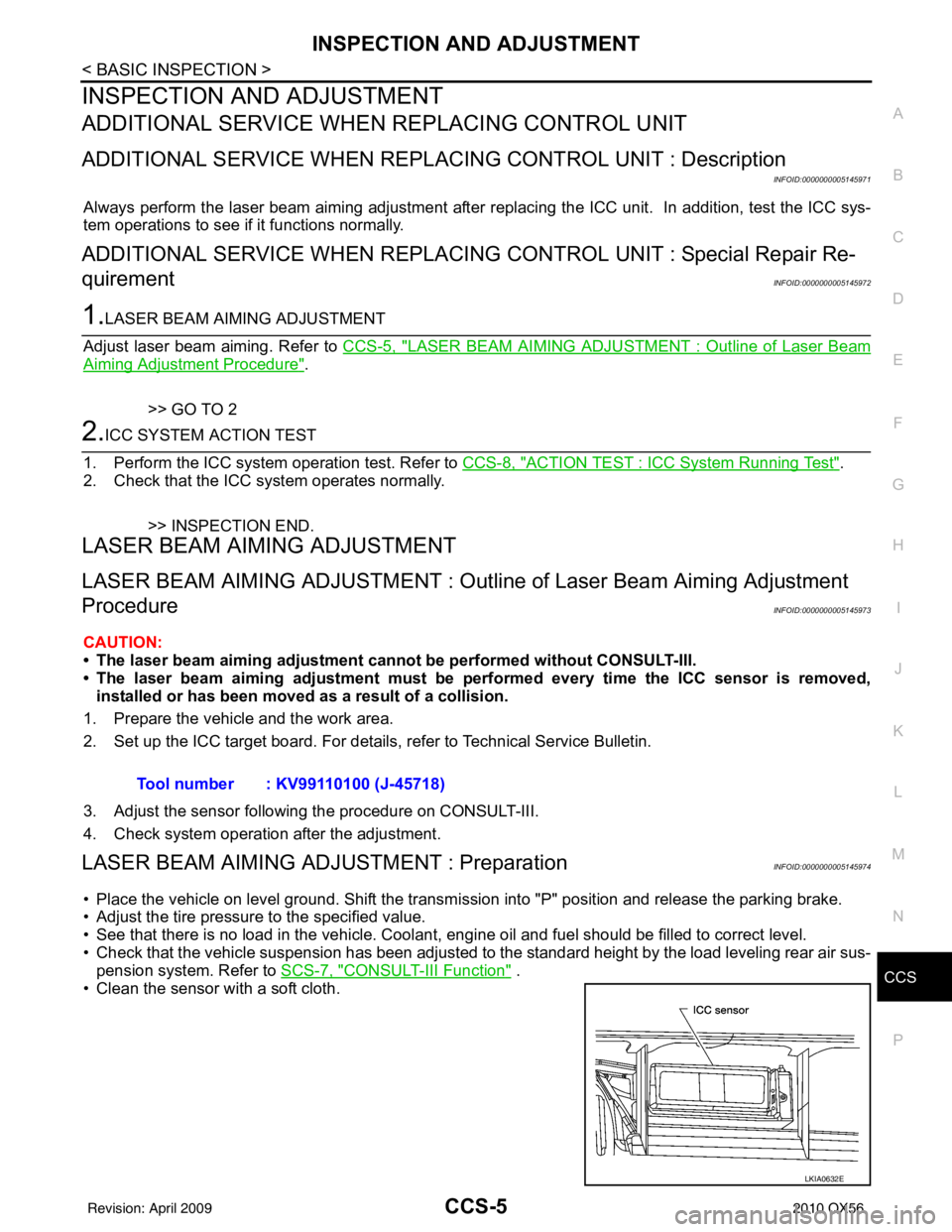
1. Prepare the vehicle and the work area.
2. Set up the ICC target board. For details, refer to Technical Service Bulletin.
3. Adjust the sensor following the procedure on CONSULT-III.
4. Check system operation after the adjustment.
LASER BEAM AIMING ADJU STMENT : PreparationINFOID:0000000005145974
• Place the vehicle on level ground. Shift the transmi ssion into "P" position and release the parking brake.
• Adjust the tire pressure to the specified value.
• See that there is no load in the vehicle. Coolant , engine oil and fuel should be filled to correct level.
• Check that the vehicle suspension has been adjusted to the standard height by the load leveling rear air sus-
pension system. Refer to SCS-7, "
CONSULT-III Function" .
• Clean the sensor with a soft cloth. Tool number : KV99110100 (J-45718)
LKIA0632E
Revision: April 20092010 QX56
Page 776 of 4210

CO-12
< ON-VEHICLE MAINTENANCE >
ENGINE COOLANT
5. Remove the reservoir tank to drain the engine coolant, then clean the reservoir tank before installing it.
6. Check the drained coolant for contaminants such as rust, corrosion or discoloration.
If the coolant is contaminated, flus h the engine cooling system. Refer to CO-11, "
Changing Engine Cool-
ant".
REFILLING ENGINE COOLANT
1. Close the radiator drain plug. Install the reservoir t ank, cylinder block drain plug, and the oil cooler hose, if
removed for a total system drain or for engine removal or repair.
• The radiator must be completely empty of coolant and water.
• Apply sealant to the threads of the cylinder bl ock drain plug. Use Genuine High Performance Thread
Sealant or equivalent. Refer to GI-15, "
Recommended Chemical Products and Sealants".
2. Set the vehicle heater controls to the full HOT and heat er ON position. Turn the vehicle ignition ON with
the engine OFF as necessary to activate the heater mode.
3. Remove the vented reservoir cap and replace it with a non-vented reservoir cap before filling the cooling
system.
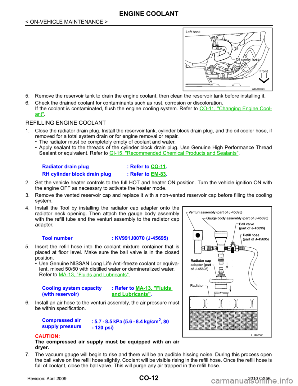
4. Install the Tool by installing the radiator cap adapter onto the radiator neck opening. Then attach the gauge body assembly
with the refill tube and the venturi assembly to the radiator cap
adapter.
5. Insert the refill hose into the coolant mixture container that is placed at floor level. Make sure the ball valve is in the closed
position.
• Use Genuine NISSAN Long Life Anti-freeze coolant or equiva-lent, mixed 50/50 with distilled water or demineralized water.
Refer to MA-13, "
Fluids and Lubricants".
6. Install an air hose to the venturi assembly, the air pressure must be within specification.
CAUTION:
The compressed air supply must be equipped with an air
dryer.
7. The vacuum gauge will begin to rise and there will be an audible hissing noise. During this process open the ball valve on the refill hose slightly. Coolant will be vi sible rising in the refill hose. Once the refill hose is
full of coolant, close the ball valve. This will purge any air trapped in the refill hose.
WBIA0392E
Radiator drain plug : Refer to CO-11.
RH cylinder block drain plug : Refer to EM-83
.
Tool number : KV991J0070 (J-45695)
Cooling system capacity
(with reservoir) : Refer to
MA-13, "
Fluids
and Lubricants".
Compressed air
supply pressure : 5.7 - 8.5 kPa (5.6 - 8.4 kg/cm
2, 80
- 120 psi)
LLIA0058E
Revision: April 20092010 QX56
Page 1201 of 4210
![INFINITI QX56 2010 Factory Service Manual NOISE, VIBRATION AND HARSHNESS (NVH) TROUBLESHOOTINGDLN-119
< SYMPTOM DIAGNOSIS > [ATX14B]
C
EF
G H
I
J
K L
M A
B
DLN
N
O P
NOISE, VIBRATION AND HARSHN ESS (NVH) TROUBLESHOOTING
NVH Troubleshooting Ch INFINITI QX56 2010 Factory Service Manual NOISE, VIBRATION AND HARSHNESS (NVH) TROUBLESHOOTINGDLN-119
< SYMPTOM DIAGNOSIS > [ATX14B]
C
EF
G H
I
J
K L
M A
B
DLN
N
O P
NOISE, VIBRATION AND HARSHN ESS (NVH) TROUBLESHOOTING
NVH Troubleshooting Ch](/img/42/57032/w960_57032-1200.png)
NOISE, VIBRATION AND HARSHNESS (NVH) TROUBLESHOOTINGDLN-119
< SYMPTOM DIAGNOSIS > [ATX14B]
C
EF
G H
I
J
K L
M A
B
DLN
N
O P
NOISE, VIBRATION AND HARSHN ESS (NVH) TROUBLESHOOTING
NVH Troubleshooting ChartINFOID:0000000005148877
Use the chart below to help you find the cause of the symptom. The numbers indicate the order of the inspec-
tion. If necessary, repair or replace these parts.
Reference page
MA-13, "
Fluids and Lubricants
"
DLN-142, "
Disassembly and Assembly
"
DLN-142, "
Disassembly and Assembly
"
DLN-142, "
Disassembly and Assembly
"
DLN-142, "
Disassembly and Assembly
"
SUSPECTED PARTS
(Possible cause)
TRANSFER FLUID (Level low)
TRANSFER FLUID (Wrong)
TRANSFER FLUID (Level too high)
LIQUID GASKET (Damaged)
O-RING (Worn or damaged)
OIL SEAL (Worn or damaged)
SHIFT FORK (Worn or damaged)
GEAR (Worn or damaged)
BEARING (Worn or damaged)
Symptom Noise
1 2 3 3
Transfer fluid leakage 31222
Hard to shift or will not shift 1 1 2
Revision: April 20092010 QX56
Page 1214 of 4210
![INFINITI QX56 2010 Factory Service Manual DLN-132
< ON-VEHICLE REPAIR >[ATX14B]
FRONT OIL SEAL
1. Install the new front oil seal until it is flush with the end face of
the front case using Tool.
CAUTION:
• Do not reuse oil seal.
• Apply p INFINITI QX56 2010 Factory Service Manual DLN-132
< ON-VEHICLE REPAIR >[ATX14B]
FRONT OIL SEAL
1. Install the new front oil seal until it is flush with the end face of
the front case using Tool.
CAUTION:
• Do not reuse oil seal.
• Apply p](/img/42/57032/w960_57032-1213.png)
DLN-132
< ON-VEHICLE REPAIR >[ATX14B]
FRONT OIL SEAL
1. Install the new front oil seal until it is flush with the end face of
the front case using Tool.
CAUTION:
• Do not reuse oil seal.
• Apply petroleum jelly to oil seal.
2. Align the matching mark of the front drive shaft with the match- ing mark of the companion flange, then install the companion
flange.
3. Install the new self-lock nut. Tighten to the specified torque using suitable tool. Refer to DLN-142, "
Disassembly and
Assembly".
CAUTION:
Do not reuse self-lock nut.
4. Install the front propeller shaft. Refer to DLN-186, "
Removal and
Installation".
5. Refill the transfer with fluid and check for fluid leakage and fluid level. Refer to DLN-129, "
Inspection".
Tool number : KV38100500 ( — )
SDIA2662E
SDIA2658E
LDIA0147E
Revision: April 20092010 QX56
Page 1216 of 4210
![INFINITI QX56 2010 Factory Service Manual DLN-134
< ON-VEHICLE REPAIR >[ATX14B]
REAR OIL SEAL
3. Install the new dust cover to the rear case using Tool.
CAUTION:
• Do not reuse dust cover.
• Apply petroleum jelly to dust cover.
4. Install INFINITI QX56 2010 Factory Service Manual DLN-134
< ON-VEHICLE REPAIR >[ATX14B]
REAR OIL SEAL
3. Install the new dust cover to the rear case using Tool.
CAUTION:
• Do not reuse dust cover.
• Apply petroleum jelly to dust cover.
4. Install](/img/42/57032/w960_57032-1215.png)
DLN-134
< ON-VEHICLE REPAIR >[ATX14B]
REAR OIL SEAL
3. Install the new dust cover to the rear case using Tool.
CAUTION:
• Do not reuse dust cover.
• Apply petroleum jelly to dust cover.
4. Install the rear propeller shaft. Refer to DLN-196, "
Removal and
Installation".
5. Refill the transfer with fluid and check for fluid leakage and fluid level. Refer to DLN-129, "
Replacement".
Tool number : KV40105310 ( — )PDIA0116E
Revision: April 20092010 QX56
Page 1223 of 4210
![INFINITI QX56 2010 Factory Service Manual TRANSFER ASSEMBLYDLN-141
< REMOVAL AND INSTALLATION > [ATX14B]
C
EF
G H
I
J
K L
M A
B
DLN
N
O P
REMOVAL AND INSTALLATION
TRANSFER ASSEMBLY
Removal and InstallationINFOID:0000000005148894
REMOVAL
1. Se INFINITI QX56 2010 Factory Service Manual TRANSFER ASSEMBLYDLN-141
< REMOVAL AND INSTALLATION > [ATX14B]
C
EF
G H
I
J
K L
M A
B
DLN
N
O P
REMOVAL AND INSTALLATION
TRANSFER ASSEMBLY
Removal and InstallationINFOID:0000000005148894
REMOVAL
1. Se](/img/42/57032/w960_57032-1222.png)
TRANSFER ASSEMBLYDLN-141
< REMOVAL AND INSTALLATION > [ATX14B]
C
EF
G H
I
J
K L
M A
B
DLN
N
O P
REMOVAL AND INSTALLATION
TRANSFER ASSEMBLY
Removal and InstallationINFOID:0000000005148894
REMOVAL
1. Set transfer state as 2WD when 4WD shift switch is at 2WD.
2. Remove the undercovers using power tool.
3. Drain the transfer fluid. Refer to TM-150, "
Changing the A/T Fluid (ATF)".
4. Remove the center exhaust tube and main muffler. Refer to EX-6, "
Removal and Installation".
5. Remove the front and rear propeller shafts. Refer to DLN-186, "
Removal and Installation" (front), DLN-
196, "Removal and Installation" (rear).
CAUTION:
Do not damage spline, sleeve yoke and rear oi l seal when removing rear propeller shaft.
NOTE:
Insert a plug into the rear oil seal after removing the rear propeller shaft.
6. Remove the A/T nuts from the A/T crossmember. Refer to TM-188, "
Removal and Installation (4WD)".
7. Position two suitable jacks under the A/T and transfer assembly.
8. Remove the crossmember. Refer to TM-188, "
Removal and Installation (4WD)".
WARNING:
Support A/T and transfer assembly using two suitable jacks while removing crossmember.
9. Disconnect the electrical connectors from the following: • ATP switch
• Neutral 4LO switch
• Wait detection switch
• Transfer motor
• Transfer control device
• Transfer terminal cord assembly
10. Disconnect each air breather hose from the following. Refer to DLN-137, "
Removal and Installation".
• Actuator
• Breather tube (transfer)
• Transfer motor
11. Remove the transfer control dev ice from the extension housing.
12. Remove the transfer to A/T and A/T to transfer bolts.
13. Remove the transfer assembly. WARNING:
Support transfer assembly with su itable jack while removing it.
CAUTION:
Do not damage rear oil seal (A/T).
INSTALLATION
Installation is in the reverse order of removal.
• Tighten the bolts to specification.
• Fill the transfer with new fluid and check for fluid leakage and fluid level. Refer to DLN-129, "
Replacement".
• Start the engine for one minute. Then stop the engine and recheck the transfer fluid. Refer to DLN-129, "
Inspection".
Transfer bolt torque : 36 N·m (3.7 kg-m, 27 ft-lb)
SMT872C
Revision: April 20092010 QX56