check engine INFINITI QX56 2011 Factory Service Manual
[x] Cancel search | Manufacturer: INFINITI, Model Year: 2011, Model line: QX56, Model: INFINITI QX56 2011Pages: 5598, PDF Size: 94.53 MB
Page 951 of 5598
ENGINE COOLANTCO-9
< PERIODIC MAINTENANCE >
C
DE
F
G H
I
J
K L
M A
CO
NP
O
3. Check drained engine coolant for contaminants such as rust, corrosion or discoloration.
If contaminated, flush the engine cooling system. Refer to CO-10, "
Flushing".
RefillingINFOID:0000000006289659
1. Install reservoir tank if removed, and radiator drain plug.
CAUTION:
Be sure to clean drain plug and install with new O-ring. Refer to CO-13, "
Exploded View".
If water drain plug on cylinder block is removed, close and tighten it. Refer to EM-107, "
Disassem-
bly and Assembly".
2. Check that each hose clamp is firmly tightened.
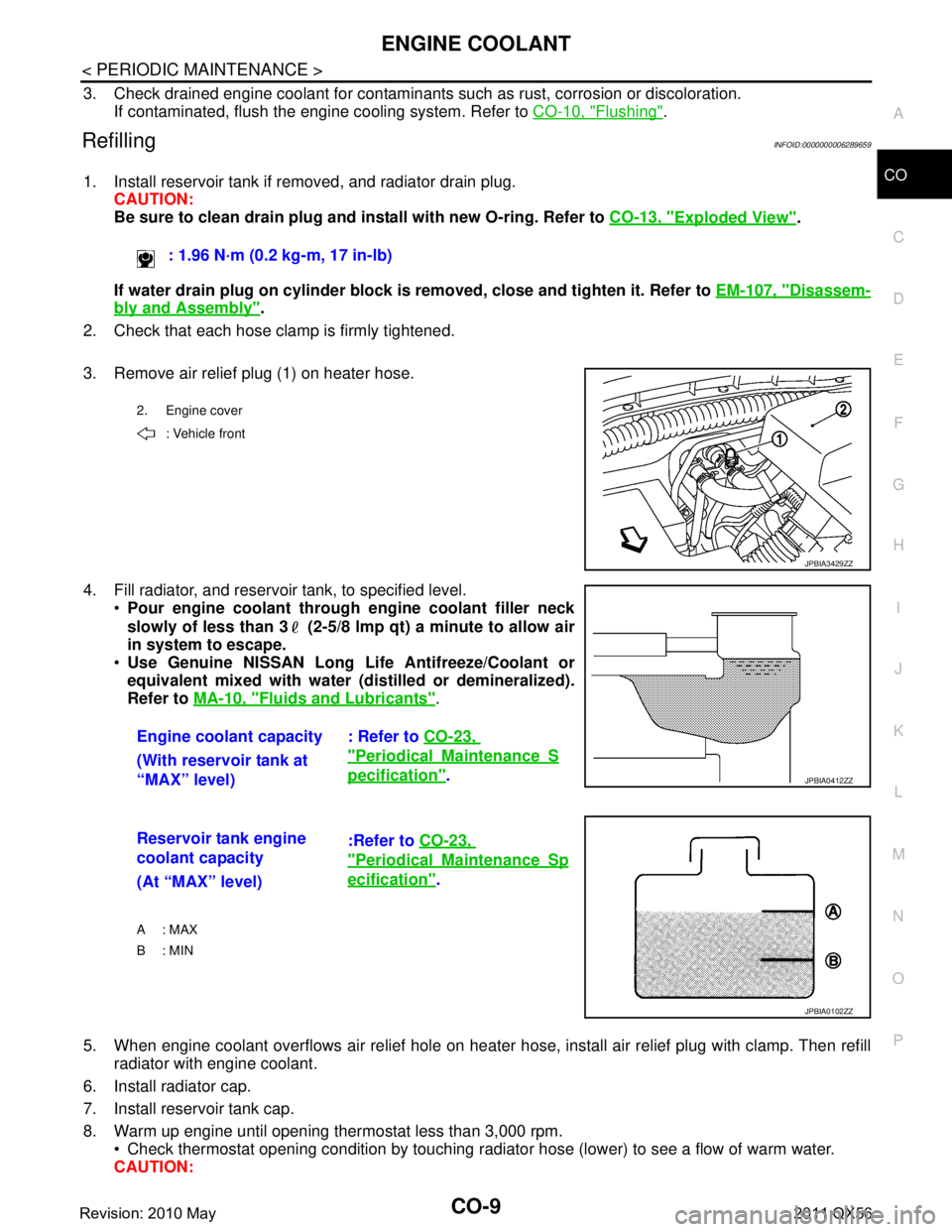
3. Remove air relief plug (1) on heater hose.
4. Fill radiator, and reservoir tank, to specified level. Pour engine coolant through engine coolant filler neck
slowly of less than 3 (2-5/8 lmp qt) a minute to allow air
in system to escape.
Use Genuine NISSAN Long Li fe Antifreeze/Coolant or
equivalent mixed with water (dis tilled or demineralized).
Refer to MA-10, "
Fluids and Lubricants".
5. When engine coolant overflows air relief hole on heater hos e, install air relief plug with clamp. Then refill
radiator with engine coolant.
6. Install radiator cap.
7. Install reservoir tank cap.
8. Warm up engine until opening thermostat less than 3,000 rpm. Check thermostat opening condition by touching radiat or hose (lower) to see a flow of warm water.
CAUTION: : 1.96 N·m (0.2 kg-m, 17 in-lb)
2. Engine cover
: Vehicle front
JPBIA3429ZZ
Engine coolant capacity : Refer to CO-23,
"PeriodicalMaintenanceS
pecification".
(With reservoir tank at
“MAX” level)JPBIA0412ZZ
Reservoir tank engine
coolant capacity :Refer to
CO-23,
"PeriodicalMaintenanceSp
ecification".
(At “MAX” level)
A : MAX
B: MIN
JPBIA0102ZZ
Revision: 2010 May2011 QX56
Page 952 of 5598
CO-10
< PERIODIC MAINTENANCE >
ENGINE COOLANT
Watch water temperature gauge so as not to overheat engine.
9. Stop the engine and cool down to less than approximately 50 °C (122 °F).
Cool down using fan to reduce the time.
If necessary, refill radiator up to filler neck with engine coolant.
10. Refill reservoir tank to “MAX” level line with engine coolant if necessary.
11. Repeat steps 6 through 10 two or more times with reservoir tank cap installed until engine coolant level no longer drops.
12. Check cooling system for leakage with engine running.
13. Warm up the engine, and check for sound of engine coolant flow while running engine from idle up to 3,000 rpm with heater temperature controller set at several position between “COOL” and “WARM”.
Sound may be noticeable at heater unit.
14. Repeat step 13 three times.
15. If sound is heard, bleed air from cooling system by repeating step 4, and steps from 6 to 14 until engine
coolant level no longer drops.
FlushingINFOID:0000000006289660
1. Install reservoir tank if removed, and radiator drain plug. CAUTION:
Be sure to clean drain plug and install with new O-ring. Refer to CO-13, "
Exploded View".
If water drain plug on cylinder block is removed, close and tighten it. Refer to EM-107, "
Disassem-
bly and Assembly".
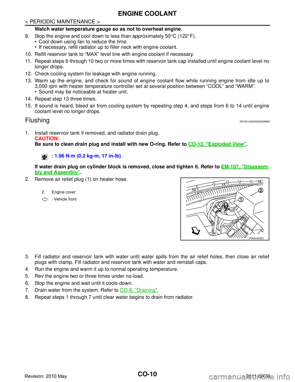
2. Remove air relief plug (1) on heater hose.
3. Fill radiator and reservoir tank with water until water spills from the air relief holes, then close air relief
plugs with clamp. Fill radiator and reservoir tank with water and reinstall caps.
4. Run the engine and warm it up to normal operating temperature.
5. Rev the engine two or three times under no-load.
6. Stop the engine and wait until it cools down.
7. Drain water from the system. Refer to CO-8, "
Draining".
8. Repeat steps 1 through 7 until clear water begins to drain from radiator. : 1.96 N·m (0.2 kg-m, 17 in-lb)
2. Engine cover
: Vehicle front
JPBIA3429ZZ
Revision: 2010 May2011 QX56
Page 953 of 5598
RADIATORCO-11
< PERIODIC MAINTENANCE >
C
DE
F
G H
I
J
K L
M A
CO
NP
O
RADIATOR
RESERVOIR TANK CAP
RESERVOIR TANK CAP : InspectionINFOID:0000000006289661
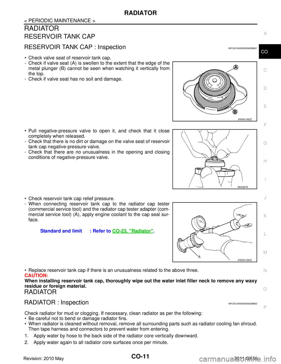
Check valve seat of reservoir tank cap.
- Check if valve seat (A) is swollen to the extent that the edge of the
metal plunger (B) cannot be seen when watching it vertically from
the top.
- Check if valve seat has no soil and damage.
Pull negative-pressure valve to open it, and check that it close completely when released.
- Check that there is no dirt or dam age on the valve seat of reservoir
tank cap negative-pressure valve.
- Check that there are no unusualness in the opening and closing conditions of negative-pressure valve.
Check reservoir tank cap relief pressure.
- When connecting reservoir tank cap to the radiator cap tester (commercial service tool) and the r adiator cap tester adapter (com-
mercial service tool) (A), apply engine coolant to the cap seal sur-
face.
Replace reservoir tank cap if there is an unusualness related to the above three.
CAUTION:
When installing reservoir tank cap , thoroughly wipe out the water inlet filler neck to remove any waxy
residue or foreign material.
RADIATOR
RADIATOR : InspectionINFOID:0000000006289662
Check radiator for mud or clogging. If neces sary, clean radiator as per the following:
Be careful not to bend or damage radiator fins.
When radiator is cleaned without removal, remove all surrounding parts such as radiator cooling fan shroud. Then tape harness and connectors to prevent water from entering.
1. Apply water by hose to the back side of the radiator core vertically downward.
2. Apply water again to all radiator core surfaces once per minute.
JPBIA0108ZZ
SMA967B
Standard and limit : Refer to CO-23, "Radiator".
JPBIA0109ZZ
Revision: 2010 May2011 QX56
Page 957 of 5598
RADIATORCO-15
< REMOVAL AND INSTALLATION >
C
DE
F
G H
I
J
K L
M A
CO
NP
O
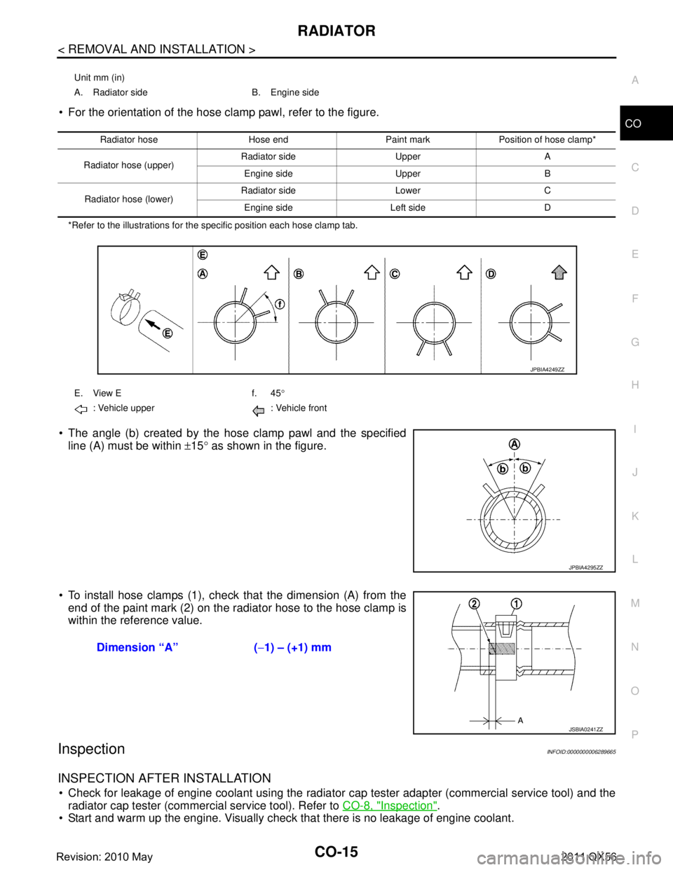
For the orientation of the hose clamp pawl, refer to the figure.
*Refer to the illustrations for the specific position each hose clamp tab.
The angle (b) created by the hose clamp pawl and the specified
line (A) must be within ±15 ° as shown in the figure.
To install hose clamps (1), check that the dimension (A) from the end of the paint mark (2) on the radiator hose to the hose clamp is
within the reference value.
InspectionINFOID:0000000006289665
INSPECTION AFTER INSTALLATION
Check for leakage of engine coolant using the radiator cap tester adapter (commercial service tool) and the
radiator cap tester (commercial service tool). Refer to CO-8, "
Inspection".
Start and warm up the engine. Visually check that there is no leakage of engine coolant.
Unit mm (in)
A. Radiator side B. Engine side
Radiator hose Hose end Paint mark Position of hose clamp*
Radiator hose (upper) Radiator side Upper A
Engine side Upper B
Radiator hose (lower) Radiator side Lower C
Engine side Left side D
E. View E f. 45 °
: Vehicle upper : Vehicle front
JPBIA4249ZZ
JPBIA4295ZZ
Dimension “A” ( −1) – (+1) mm
JSBIA0241ZZ
Revision: 2010 May2011 QX56
Page 959 of 5598
COOLING FANCO-17
< REMOVAL AND INSTALLATION >
C
DE
F
G H
I
J
K L
M A
CO
NP
O
13. Remove the fan bracket, refer to following.
Disconnect A/C compressor harness connector. Refer to HA-30, "
Exploded View".
Remove A/C compressor mounting bolt. Refer to HA-30, "
Exploded View".
Remove fan bracket mounting bolt.
INSTALLATION
Installation is in the reverse order of removal.
InspectionINFOID:0000000006289668
INSPECTION AFTER REMOVAL
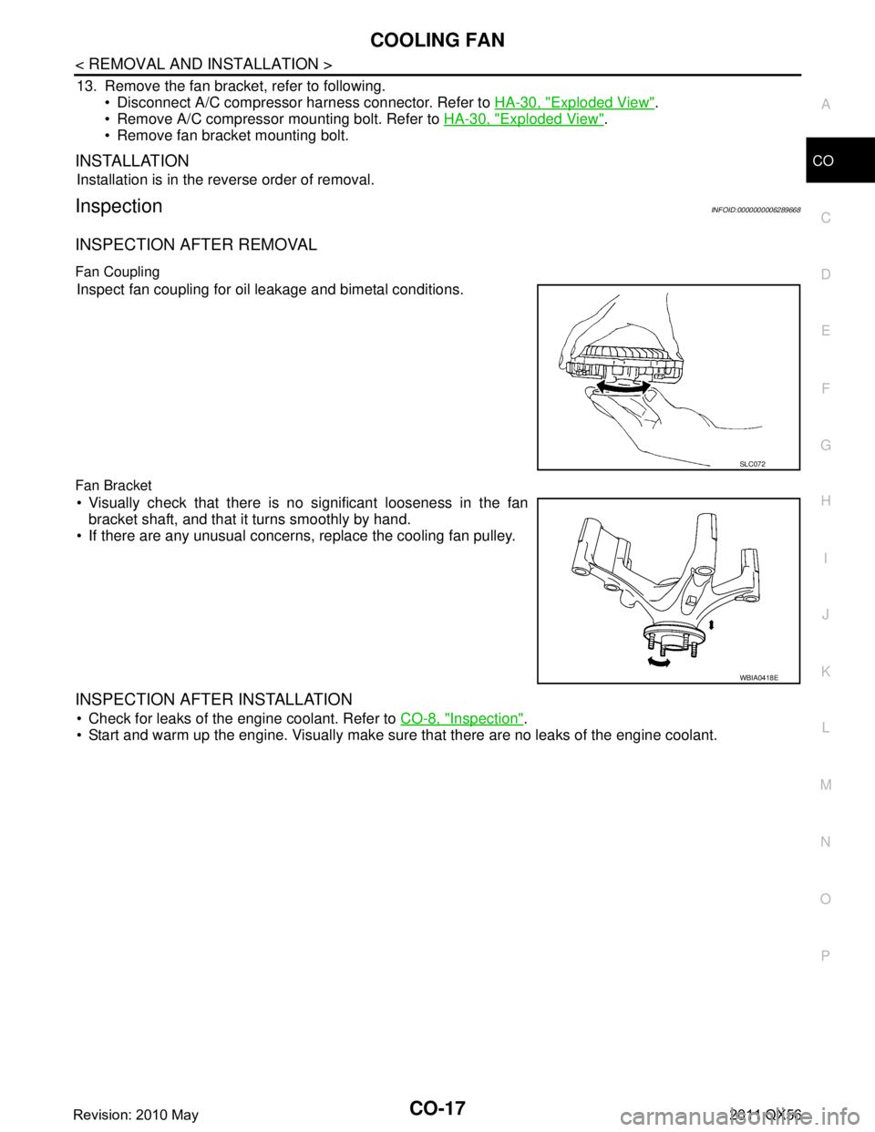
Fan Coupling
Inspect fan coupling for oil leakage and bimetal conditions.
Fan Bracket
Visually check that there is no significant looseness in the fan bracket shaft, and that it turns smoothly by hand.
If there are any unusual concerns, replace the cooling fan pulley.
INSPECTION AFTER INSTALLATION
Check for leaks of the engine coolant. Refer to CO-8, "Inspection".
Start and warm up the engine. Visually make sure that there are no leaks of the engine coolant.
SLC072
WBIA0418E
Revision: 2010 May2011 QX56
Page 960 of 5598
CO-18
< REMOVAL AND INSTALLATION >
WATER PUMP
WATER PUMP
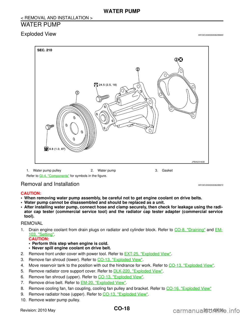
Exploded ViewINFOID:0000000006289669
Removal and InstallationINFOID:0000000006289670
CAUTION:
When removing water pump assembly, be careful not to get engine coolant on drive belts.
Water pump cannot be disassembled and should be replaced as a unit.
After installing water pump, co nnect hose and clamp securely, then check for leakage using the radi-
ator cap tester (commercial service tool) and the radiator cap tester adapter (commercial service
tool).
REMOVAL
1. Drain engine coolant from drain plugs on radiator and cylinder block. Refer to CO-8, "Draining" and EM-
103, "Setting".
CAUTION:
Perform this step when engine is cold.
Never spill engine coolant on drive belt.
2. Remove front under cover with power tool. Refer to EXT-25, "
Exploded View".
3. Remove fan shroud (lower). Refer to CO-13, "
Exploded View".
4. Move reservoir tank to the position with out the hindrance for work. Refer to CO-13, "
Exploded View".
5. Remove radiator core support cover. Refer to DLK-220, "
Exploded View".
6. Remove fan shroud (upper). Refer to CO-13, "
Exploded View".
7. Remove drive belt. Refer to EM-20, "
Exploded View".
8. Remove cooling fan, fan coupling, cooling fan pulley and bracket. Refer to CO-16, "
Exploded View"
9. Remove radiator hose (upper). Refer to CO-13, "Exploded View".
10. Remove water pump pulley.
1. Water pump pulley 2. Water pump 3. Gasket
Refer to GI-4, "
Components" for symbols in the figure.
JPBIA2316GB
Revision: 2010 May2011 QX56
Page 961 of 5598
WATER PUMPCO-19
< REMOVAL AND INSTALLATION >
C
DE
F
G H
I
J
K L
M A
CO
NP
O
11. Remove water pump. Refer to
CO-18, "Exploded View".
Engine coolant will leak from cylinder block, so have a receptacle ready under vehicle.
CAUTION:
Handle the water pump vane so that it does not contact any other parts.
Never disassemble water pump.
INSTALLATION
Install in the reverse order of removal.
InspectionINFOID:0000000006289671
INSPECTION AFTER REMOVAL
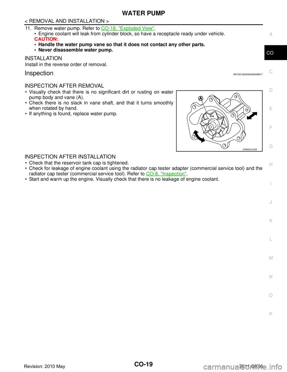
Visually check that there is no significant dirt or rusting on water pump body and vane (A).
Check there is no slack in vane shaft, and that it turns smoothly when rotated by hand.
If anything is found, replace water pump.
INSPECTION AFTER INSTALLATION
Check that the reservoir tank cap is tightened.
Check for leakage of engine coolant using the radiator cap tester adapter (commercial service tool) and the
radiator cap tester (commercial service tool). Refer to CO-8, "
Inspection".
Start and warm up the engine. Visually check that there is no leakage of engine coolant.
JPBIA2315ZZ
Revision: 2010 May2011 QX56
Page 963 of 5598
WATER INLET AND THERMOSTAT ASSEMBLYCO-21
< REMOVAL AND INSTALLATION >
C
DE
F
G H
I
J
K L
M A
CO
NP
O
2. Remove front under cover with power tool. Refer to
EXT-25, "Exploded View".
3. Drain engine coolant from drain plugs on radiator and cylinder block. Refer to CO-8, "
Draining" and EM-
103, "Setting".
CAUTION:
Perform this step when engine is cold.
Never spill engine coolant on drive belts.
4. Disconnect radiator hose (upper and lower). Refer to CO-13, "
Exploded View".
5. Remove intake manifold. Refer to EM-30, "
Exploded View".
6. Remove fuel feed tube. Refer to EM-43, "
Exploded View".
7. Remove water hose, water connector, heater pipes and heater hoses.
8. Remove thermostat housing.
9. Remove water inlet and thermostat.
INSTALLATION
Note the following, and install in the reverse order of removal.
CAUTION:
Be careful not to spill engine coolant over en gine room. Use rag to absorb engine coolant.
Thermostat
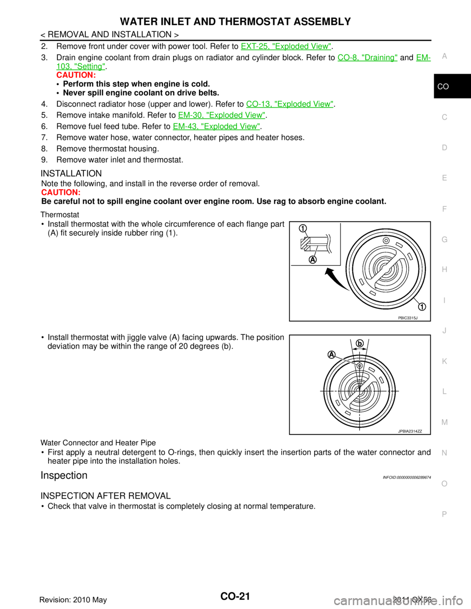
Install thermostat with the whole circumference of each flange part
(A) fit securely inside rubber ring (1).
Install thermostat with jiggle valve (A) facing upwards. The position deviation may be within the range of 20 degrees (b).
Water Connector and Heater Pipe
First apply a neutral detergent to O-rings, then quickly in sert the insertion parts of the water connector and
heater pipe into the installation holes.
InspectionINFOID:0000000006289674
INSPECTION AFTER REMOVAL
Check that valve in thermostat is co mpletely closing at normal temperature.
PBIC3315J
JPBIA2314ZZ
Revision: 2010 May2011 QX56
Page 964 of 5598
CO-22
< REMOVAL AND INSTALLATION >
WATER INLET AND THERMOSTAT ASSEMBLY
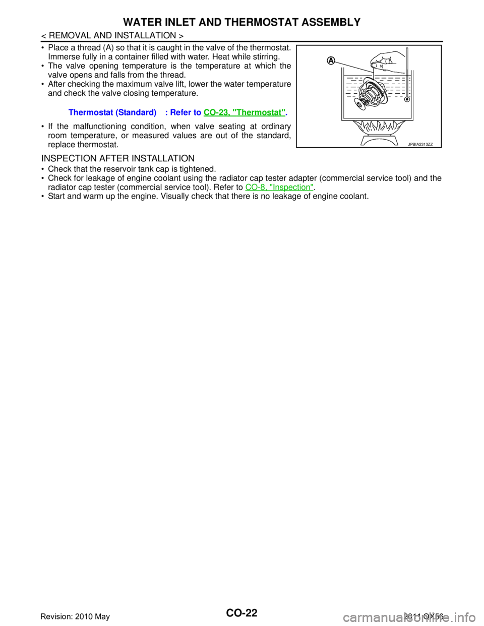
Place a thread (A) so that it is caught in the valve of the thermostat.Immerse fully in a container filled with water. Heat while stirring.
The valve opening temperature is the temperature at which the
valve opens and falls from the thread.
After checking the maximum valve lift, lower the water temperature and check the valve closing temperature.
If the malfunctioning condition, when valve seating at ordinary room temperature, or measured values are out of the standard,
replace thermostat.
INSPECTION AFTER INSTALLATION
Check that the reservoir tank cap is tightened.
Check for leakage of engine coolant using the radiator cap tester adapter (commercial service tool) and the
radiator cap tester (commercial service tool). Refer to CO-8, "
Inspection".
Start and warm up the engine. Visually chec k that there is no leakage of engine coolant.
Thermostat (Standard) : Refer to
CO-23, "
Thermostat".
JPBIA2313ZZ
Revision: 2010 May2011 QX56
Page 986 of 5598
![INFINITI QX56 2011 Factory Service Manual
DAS
DIAGNOSIS SYSTEM (ADAS CONTROL UNIT)
DAS-21
< SYSTEM DESCRIPTION > [ADAS CONTROL UNIT]
C
D
E
F
G H
I
J
K L
M B
N P A
It displays for up to 5 minutes and then stops.
If multiple malfunctions e INFINITI QX56 2011 Factory Service Manual
DAS
DIAGNOSIS SYSTEM (ADAS CONTROL UNIT)
DAS-21
< SYSTEM DESCRIPTION > [ADAS CONTROL UNIT]
C
D
E
F
G H
I
J
K L
M B
N P A
It displays for up to 5 minutes and then stops.
If multiple malfunctions e](/img/42/57033/w960_57033-985.png)
DAS
DIAGNOSIS SYSTEM (ADAS CONTROL UNIT)
DAS-21
< SYSTEM DESCRIPTION > [ADAS CONTROL UNIT]
C
D
E
F
G H
I
J
K L
M B
N P A
It displays for up to 5 minutes and then stops.
If multiple malfunctions exist, up to 6 DTCs can be stored in memory at the most, and the most recent
one is displayed first.
WHEN THE ON BOARD SELF-DIAGNOSIS DOES NOT START
If the on board self-diagnosis does not start, check the following items.
HOW TO ERASE ON BOARD SELF-DIAGNOSIS
1. Turn the ignition switch OFF.
2. Start the engine, and then start the on board self-diagnosis.
3. Press the CANCEL switch 5 times, and then press the DIS-
TANCE switch 5 times under the condition that the on board
self-diagnosis starts.
NOTE:
Complete the operation within 10 seconds after pressing the
CANCEL switch first.
If the operation is not completed within 10 seconds, repeat the procedure from step 1.
4. DTC 55 is displayed after erasing. NOTE:
DTCs for existing malfunction can not be erased.
5. Turn ignition switch OFF, and finish the diagnosis.
CONSULT-III Function (ICC/ADAS)INFOID:0000000006223475
APPLICATION ITEMS
CONSULT-III performs the following functions via CAN communication using ADAS control unit.
WORK SUPPORT
Assumed abnormal part Inspection item
Information display Combination meter malfunction Check that the self-diagnosis function of the combina-
tion meter operates. Refer to
MWI-29, "
On Board Diag-
nosis Function"
ICC steering switch malfunction
Perform the inspection for DTC“C1A06”. Refer to CCS-
94, "Diagnosis Procedure"Harness malfunction between ICC steering switch and ECM
ECM malfunction
ADAS control unit malfunction Check power supply and ground circuit of ADAS con-
trol unit. Refer to DAS-62, "
Diagnosis Procedure".
Perform SELF-DIAGNOSIS for “ICC/ADAS”with
CONSULT-III, and then check the malfunctioning
parts. Refer to DAS-38, "
DTC Index".
PKIB8373E
Diagnosis mode Description
Work Support Displays causes of automatic system cancellation occurred during system control
Self Diagnostic Result Displays the name of a malfunctioning system stored in the ADAS control unit
Data Monitor Displays ADAS control unit input/output data in real time
Active Test Enables an operational check of a load by transmitting a driving signal from the ADAS control unit to
the load
Ecu Identification Displays ADAS control unit part number
CAN Diag Support Monitor Displays a reception/transmission state of CAN communication and ITS communication
Revision: 2010 May2011 QX56