tires INFINITI QX56 2011 Factory Service Manual
[x] Cancel search | Manufacturer: INFINITI, Model Year: 2011, Model line: QX56, Model: INFINITI QX56 2011Pages: 5598, PDF Size: 94.53 MB
Page 1 of 5598
A
B
D
E
F
G
H
I
J
K
L
M
N
P
O
C
QUICK REFERENCE INDEX
AGENERAL INFORMATIONGIGeneral Information
BENGINEEMEngine Mechanical
LUEngine Lubrication System
COEngine Cooling System
ECEngine Control System
FLFuel System
EXExhaust System
STRStarting System
ACCAccelerator Control System
CHYBRIDHBCHybrid Control System
HBBHybrid Battery System
HBRHybrid Brake System
DTRANSMISSION & DRIVE-
LINECLClutch
TMTransaxle & Transmission
DLNDriveline
FAXFront Axle
RAXRear Axle
ESUSPENSIONFSUFront Suspension
RSURear Suspension
SCSSuspension Control System
WTRoad Wheels & Tires
FBRAKESBRBrake System
PBParking Brake System
BRCBrake Control System
GSTEERINGSTSteering System
STCSteering Control System
HRESTRAINTSSBSeat Belt
SBCSeat Belt Control System
SRSRS Airbag
SRCSRS Airbag Control System
IVENTILATION, HEATER &
AIR CONDITIONERVTLVentilation System
HAHeater & Air Conditioning System
HACHeater & Air Conditioning Control System
JBODY INTERIORINTInterior
IPInstrument Panel
SESeat
ADPAutomatic Drive Positioner
KBODY EXTERIOR,
DOORS, ROOF & VEHICLE
SECURITYDLKDoor & Lock
SECSecurity Control System
GWGlass & Window System
PWCPower Window Control System
RFRoof
HDHood
EXTExterior
BRMBody Repair
LDRIVER CONTROLSMIRMirrors
EXLExterior Lighting System
INLInterior Lighting System
WWWiper & Washer
DEFDefogger
HRNHorn
MELECTRICAL & POWER
CONTROLPWOPower Outlet
BCSBody Control System
LANLAN System
PCSPower Control System
CHGCharging System
PGPower Supply, Ground & Circuit Elements
NDRIVER INFORMATION &
MULTIMEDIAMWIMeter, Warning Lamp & Indicator
WCSWarning Chime System
SNSonar System
AVAudio, Visual & Navigation System
OCRUISE CONTROL &
DRIVER ASSISTANCECCSCruise Control System
DASDriver Assistance System
DMSDrive Mode System
PMAINTENANCEMAMaintenance
All rights reserved. No part
of this Service Manual may
be reproduced or stored in a
retrieval system, or transmit-
ted in any form, or by any
means, electronic, mechani-
cal, recording or otherwise,
without the prior written per-
mission of NISSAN MOTOR
CO., LTD.
Edition: May 2010
Publication No. SM1E-1Z62U0
Page 182 of 5598
AV-34
< SYSTEM DESCRIPTION >
DIAGNOSIS SYSTEM (AV CONTROL UNIT)
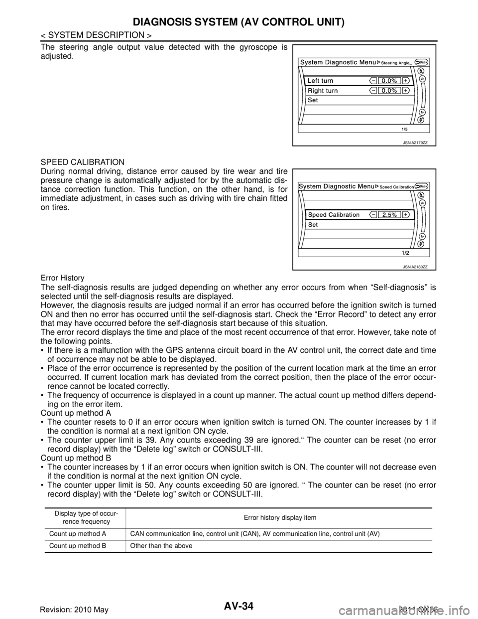
The steering angle output value detected with the gyroscope is
adjusted.
SPEED CALIBRATION
During normal driving, distance error caused by tire wear and tire
pressure change is automatically adjusted for by the automatic dis-
tance correction function. This function, on the other hand, is for
immediate adjustment, in cases such as driving with tire chain fitted
on tires.
Error History
The self-diagnosis results are judged depending on whether any error occurs from when “Self-diagnosis” is
selected until the self-diagnosis results are displayed.
However, the diagnosis results are judged normal if an error has occurred before the ignition switch is turned
ON and then no error has occurred until the self-diagnosis start. Check the “Error Record” to detect any error
that may have occurred before the self-di agnosis start because of this situation.
The error record displays the time and place of the most recent occurrence of that error. However, take note of
the following points.
If there is a malfunction with the GPS antenna circuit board in the AV control unit, the correct date and time
of occurrence may not be able to be displayed.
Place of the error occurrence is represented by the posit ion of the current location mark at the time an error
occurred. If current location mark has deviated from t he correct position, then the place of the error occur-
rence cannot be located correctly.
The frequency of occurrence is displayed in a count up manner. The actual count up method differs depend- ing on the error item.
Count up method A
The counter resets to 0 if an error occurs when igniti on switch is turned ON. The counter increases by 1 if
the condition is normal at a next ignition ON cycle.
The counter upper limit is 39. Any counts exceeding 39 are ignored.“ The counter can be reset (no error
record display) with the “Delete log” switch or CONSULT-III.
Count up method B
The counter increases by 1 if an error occurs when i gnition switch is ON. The counter will not decrease even
if the condition is normal at the next ignition ON cycle.
The counter upper limit is 50. Any counts exceeding 50 are ignored. “ The counter can be reset (no error
record display) with the “Delete log” switch or CONSULT-III.
JSNIA2179ZZ
JSNIA2180ZZ
Display type of occur-
rence frequency Error history display item
Count up method A CAN communication line, control unit (CAN), AV communication line, control unit (AV)
Count up method B Other than the above
Revision: 2010 May2011 QX56
Page 358 of 5598

AV-210
< SYMPTOM DIAGNOSIS >
NORMAL OPERATING CONDITION
RELATED TO ROUTE CALCULATION AND VISUAL GUIDANCE
The vehicle icon is not displayed in
the correct position.The vehicle was transported after the ignition
switch was pressed off, for example, by a ferry
or car transporter.
Drive the vehicle for a while on a road where
GPS signals can be received.
The position and direction of the vehicle icon
may be incorrect depending on the driving en-
vironments and the levels of positioning accu-
racy of the navigation system. This is not a malfunction. Drive the vehicle for
a while to automatically correct the position
and direction of the vehicle icon.
When the vehicle is traveling on a
new road, the vehicle icon is located
on another road nearby. Because the new road is not stored in the map
data, the system automatically places the vehi-
cle icon on the nearest road available.
Updated road information will be included in
the next version of the map data.
The screen does not switch to the
night screen even after turning on
the headlights. The daytime screen was set the last time the
headlights were turned on.
Set the screen to the night screen mode using
The map does not scroll even when
the vehicle is moving. The current location map screen is not dis-
played.
Press “MAP”.
The vehicle icon is not displayed. The current location map screen is not dis-
played.
Press “MAP”.
The location of the vehicle icon is
misaligned from the actual position. When using tire chains or replacing the tires,
speed calculations based on the speed sensor
may be incorrect. Drive the vehicle for a while [at approximately
30 km/h (19 MPH) for about 30 minutes] to
automatically correct the vehicle icon posi-
tion.
If this does not correct the vehicle icon posi-
tion, contact an INFINITI dealer.
The map data has a mistake or is incomplete
(the vehicle icon position is always misaligned
in the same area). Updated road information will be included in
the next version of the map data.
Symptom Possible cause Possible solution
Symptom Possible cause Possible solution
Waypoints are not included in
the auto reroute calculation. Waypoints that you have already passed are not included in
the auto reroute calculation. If you want to go to that waypoint
again, you need to edit the route.
Route information is not dis-
played. Route calculation has not yet been performed.
Set the destination and perform route
calculation.
You are not driving on the suggested route. Drive on the suggested route.
Route guidance is set to off. Turn on route guidance.
Route information is not provided for certain types of roads
(roads displayed in gray). This is not a malfunction.
The auto reroute calculation (or
detour calculation) suggests
the same route as the one pre-
viously suggested. Route calculations took priority conditions into consider-
ation, but the same route was calculated.
This is not a malfunction.
A waypoint cannot be added. Five waypoints are already set on the route, including ones
that you have already passed. A maximum of 5 waypoints can be set
on the route. If you want to go to 6 or
more waypoints, perform route calcu-
lations multiple times as necessary.
The suggested route is not dis-
played. Roads near the destination cannot be calculated.
Reset the destination to a main or or-
dinary road, and recalculate the route.
The starting point and destination are too close. Set a more distant destination.
The starting point and destination are too far away. Divide your trip by selecting one or two
intermediate destinations, and per-
form route calculations multiple times.
There are time restricted roads (by the day of the week, by
time) near the current vehicle location or destination. Set [Use Time Restricted Roads] to
off.
Revision: 2010 May2011 QX56
Page 493 of 5598
BRAKE PIPINGBR-23
< REMOVAL AND INSTALLATION >
C
DE
G H
I
J
K L
M A
B
BR
N
O P
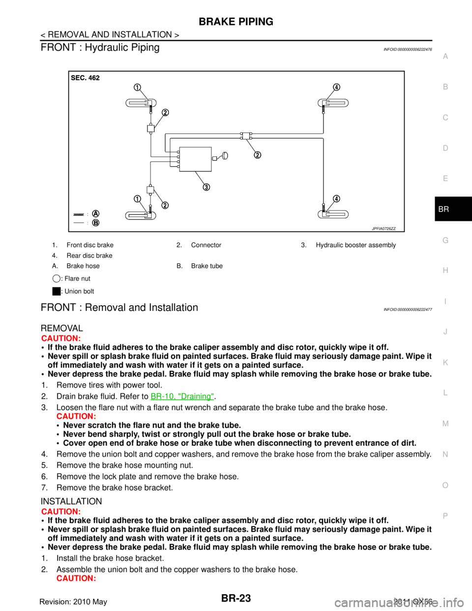
FRONT : Hydraulic PipingINFOID:0000000006222476
FRONT : Removal and InstallationINFOID:0000000006222477
REMOVAL
CAUTION:
If the brake fluid adheres to the brake caliper assembly and disc rotor, quickly wipe it off.
Never spill or splash brake fluid on painted surfaces. Brake fluid may seriously damage paint. Wipe it
off immediately and wash with wate r if it gets on a painted surface.
Never depress the brake pedal. Brake fluid may spl ash while removing the brake hose or brake tube.
1. Remove tires with power tool.
2. Drain brake fluid. Refer to BR-10, "
Draining".
3. Loosen the flare nut with a flare nut wrench and separate the brake tube and the brake hose.
CAUTION:
Never scratch the flare nut and the brake tube.
Never bend sharply, twist or strongly pull out the brake hose or brake tube.
Cover open end of brake hose or brake tube wh en disconnecting to prevent entrance of dirt.
4. Remove the union bolt and copper washers, and remove the brake hose from the brake caliper assembly.
5. Remove the brake hose mounting nut.
6. Remove the lock plate and remove the brake hose.
7. Remove the brake hose bracket.
INSTALLATION
CAUTION:
If the brake fluid adheres to the brake caliper assembly and disc rotor, quickly wipe it off.
Never spill or splash brake fluid on painted surfaces. Brake fluid may seriously damage paint. Wipe it
off immediately and wash with wate r if it gets on a painted surface.
Never depress the brake pedal. Brake fluid may spl ash while removing the brake hose or brake tube.
1. Install the brake hose bracket.
2. Assemble the union bolt and the copper washers to the brake hose. CAUTION:
1. Front disc brake 2. Connector 3. Hydraulic booster assembly
4. Rear disc brake
A. Brake hose B. Brake tube
: Flare nut
: Union bolt
JPFIA0726ZZ
Revision: 2010 May2011 QX56
Page 494 of 5598
BR-24
< REMOVAL AND INSTALLATION >
BRAKE PIPING
Never reuse the copper washer.
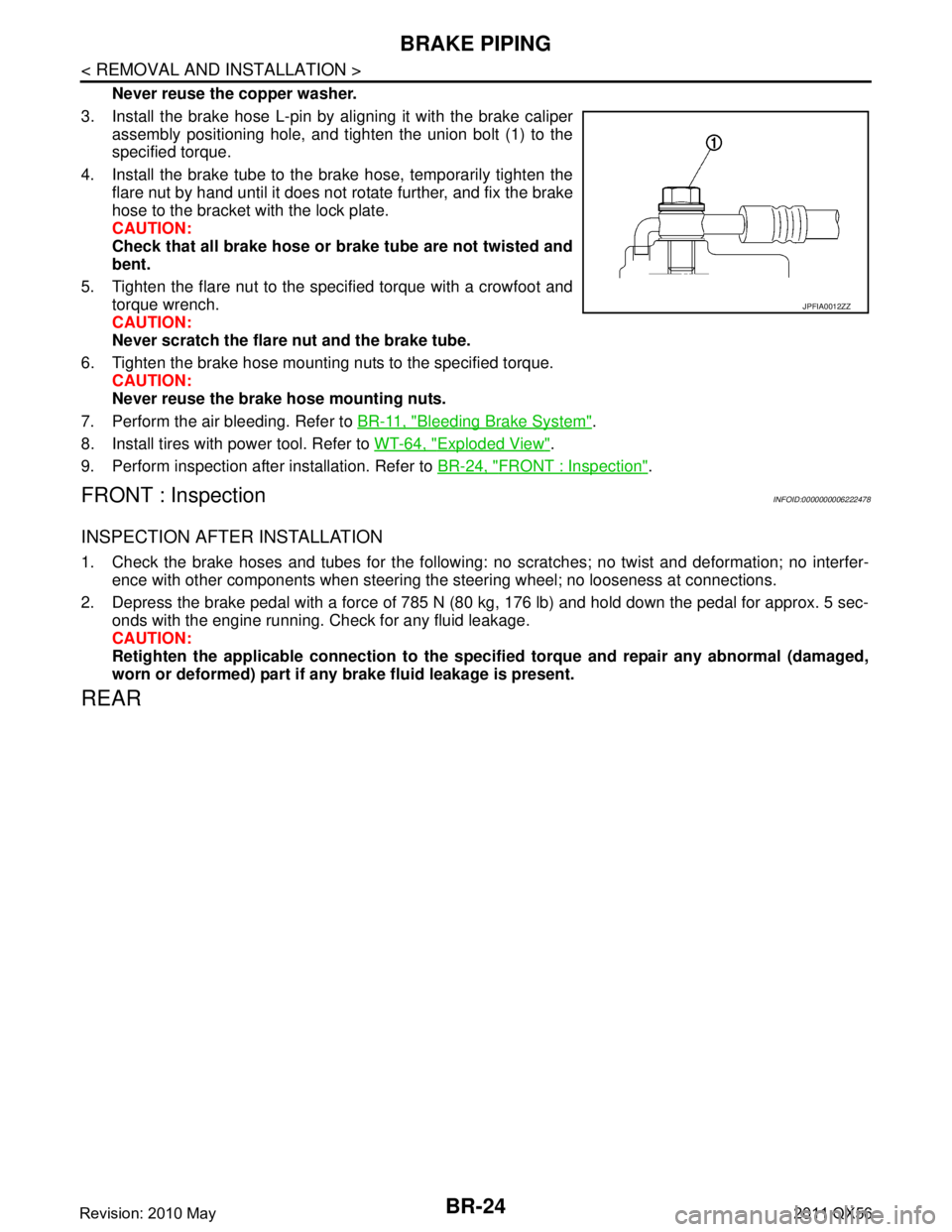
3. Install the brake hose L-pin by aligning it with the brake caliper assembly positioning hole, and tighten the union bolt (1) to the
specified torque.
4. Install the brake tube to the brake hose, temporarily tighten the flare nut by hand until it does not rotate further, and fix the brake
hose to the bracket with the lock plate.
CAUTION:
Check that all brake hose or brake tube are not twisted and
bent.
5. Tighten the flare nut to the specified torque with a crowfoot and torque wrench.
CAUTION:
Never scratch the flare nut and the brake tube.
6. Tighten the brake hose mounting nuts to the specified torque. CAUTION:
Never reuse the brake hose mounting nuts.
7. Perform the air bleeding. Refer to BR-11, "
Bleeding Brake System".
8. Install tires with power tool. Refer to WT-64, "
Exploded View".
9. Perform inspection after installation. Refer to BR-24, "
FRONT : Inspection".
FRONT : InspectionINFOID:0000000006222478
INSPECTION AFTER INSTALLATION
1. Check the brake hoses and tubes for the following: no scratches; no twist and deformation; no interfer-
ence with other components when steering the steering wheel; no looseness at connections.
2. Depress the brake pedal with a force of 785 N (80 kg, 176 lb) and hold down the pedal for approx. 5 sec- onds with the engine running. Check for any fluid leakage.
CAUTION:
Retighten the applicable connection to the specified torque and repair any abnormal (damaged,
worn or deformed) part if any brake fluid leakage is present.
REAR
JPFIA0012ZZ
Revision: 2010 May2011 QX56
Page 496 of 5598
BR-26
< REMOVAL AND INSTALLATION >
BRAKE PIPING
REAR : Removal and Installation
INFOID:0000000006222481
REMOVAL
CAUTION:
If the brake fluid adheres to the brake caliper assembly and disc rotor, quickly wipe it off.
Never spill or splash brake fluid on painted surfaces. Brake fluid may seriously damage paint. Wipe it
off immediately and wash with wate r if it gets on a painted surface.
Never depress the brake pedal. Brake fluid may spl ash while removing the brake hose or brake tube.
1. Remove tires with power tool.
2. Drain brake fluid. Refer to BR-10, "
Draining".
3. Loosen the flare nut with a flare nut wrench and separate the brake tube and the brake hose. CAUTION:
Never scratch the flare nut and the brake tube.
Never bend sharply, twist or strongly pull out the brake hose or brake tube.
Cover open end of brake hose or brake tube wh en disconnecting to prevent entrance of dirt.
4. Remove the union bolt and copper washers, and remove the brake hose from the brake caliper assembly.
5. Remove the lock plate and remove the brake hose.
INSTALLATION
CAUTION:
If the brake fluid adheres to the brake caliper assembly and disc rotor, quickly wipe it off.
Never spill or splash brake fluid on painted surfaces. Brake fluid may seriously damage paint. Wipe it
off immediately and wash with wate r if it gets on a painted surface.
Never depress the brake pedal. Brake fluid may spl ash while removing the brake hose or brake tube.
1. Assemble the union bolt and the copper washers to the brake hose. CAUTION:
Never reuse the copper washer.
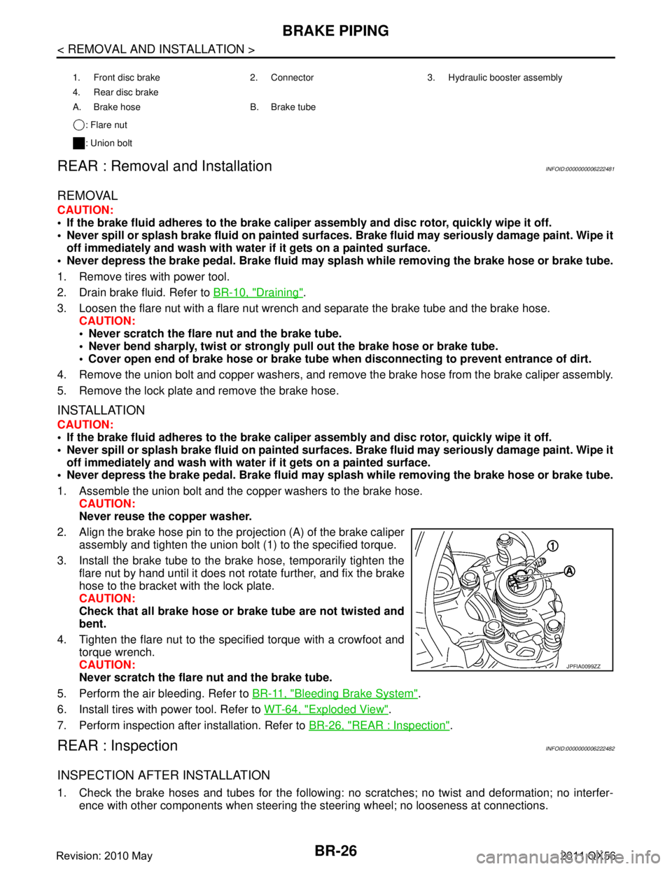
2. Align the brake hose pin to the projection (A) of the brake caliper
assembly and tighten the union bolt (1) to the specified torque.
3. Install the brake tube to the brake hose, temporarily tighten the flare nut by hand until it does not rotate further, and fix the brake
hose to the bracket with the lock plate.
CAUTION:
Check that all brake hose or brake tube are not twisted and
bent.
4. Tighten the flare nut to the specified torque with a crowfoot and torque wrench.
CAUTION:
Never scratch the flare nut and the brake tube.
5. Perform the air bleeding. Refer to BR-11, "
Bleeding Brake System".
6. Install tires with power tool. Refer to WT-64, "
Exploded View".
7. Perform inspection after installation. Refer to BR-26, "
REAR : Inspection".
REAR : InspectionINFOID:0000000006222482
INSPECTION AFTER INSTALLATION
1. Check the brake hoses and tubes for the following: no scratches; no twist and deformation; no interfer-
ence with other components when steering the steering wheel; no looseness at connections.
1. Front disc brake 2. Connector 3. Hydraulic booster assembly
4. Rear disc brake
A. Brake hose B. Brake tube
: Flare nut
: Union bolt
JPFIA0099ZZ
Revision: 2010 May2011 QX56
Page 504 of 5598
BR-34
< REMOVAL AND INSTALLATION >
FRONT DISC BRAKE
FRONT DISC BRAKE
BRAKE PAD
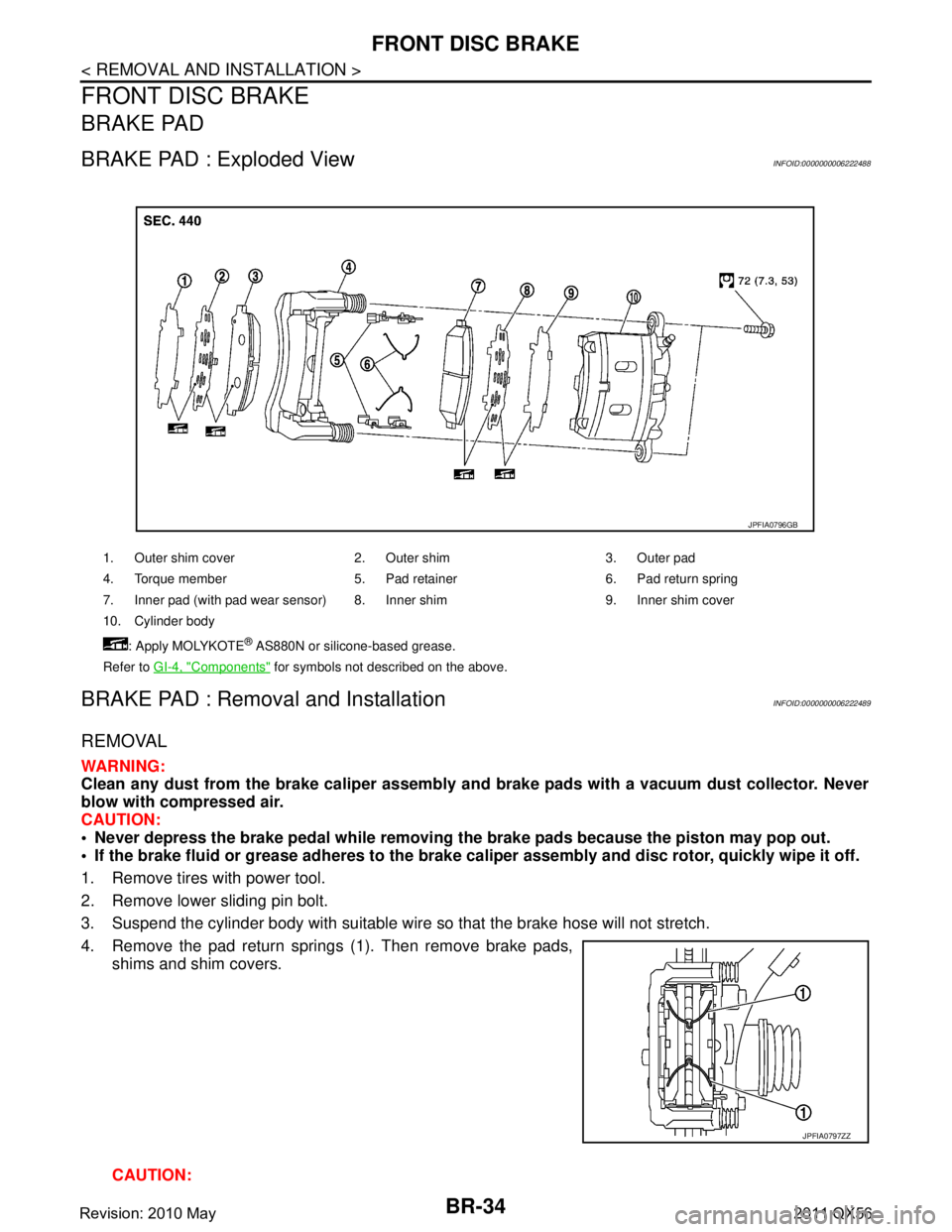
BRAKE PAD : Exploded ViewINFOID:0000000006222488
BRAKE PAD : Removal and InstallationINFOID:0000000006222489
REMOVAL
WARNING:
Clean any dust from the brake caliper assembly and brake pads with a vacuum dust collector. Never
blow with compressed air.
CAUTION:
Never depress the brake pedal while removing th e brake pads because the piston may pop out.
If the brake fluid or grease adheres to the brake calip er assembly and disc rotor, quickly wipe it off.
1. Remove tires with power tool.
2. Remove lower sliding pin bolt.
3. Suspend the cylinder body with suitable wire so that the brake hose will not stretch.
4. Remove the pad return springs (1). Then remove brake pads, shims and shim covers.
CAUTION:
1. Outer shim cover 2. Outer shim 3. Outer pad
4. Torque member 5. Pad retainer 6. Pad return spring
7. Inner pad (with pad wear sensor) 8. Inner shim 9. Inner shim cover
10. Cylinder body
: Apply MOLYKOTE
® AS880N or silicone-based grease.
Refer to GI-4, "
Components" for symbols not described on the above.
JPFIA0796GB
JPFIA0797ZZ
Revision: 2010 May2011 QX56
Page 506 of 5598

BR-36
< REMOVAL AND INSTALLATION >
FRONT DISC BRAKE
7. Depress the brake pedal several times to check that no drag feel is present for the front disc brake. Refer
to BR-36, "
BRAKE PAD : Inspection".
8. Install tires with power tool. Refer to WT-64, "
Exploded View".
BRAKE PAD : InspectionINFOID:0000000006222490
INSPECTION AFTER REMOVAL
Replace the shims and shim covers if rust is excessively attached.
Eliminate rust on the pad retainers and the torque mem ber. Replace them if rust is excessively attached.
INSPECTION AFTER INSTALLATION
1. Check a drag of front disc brake. If any drag is found, follow the procedure described below.
2. Remove brake pads. Refer to BR-34, "
BRAKE PAD : Removal and Installation".
3. Press the pistons. Refer to BR-34, "
BRAKE PAD : Removal and Installation".
4. Install brake pads. Refer to BR-34, "
BRAKE PAD : Removal and Installation".
5. Depress the brake pedal several times.
6. Check a drag of front disc brake again. If any drag is found, disassemble the caliper. Refer to BR-38,
"BRAKE CALIPER ASSEMBLY : Disassembly and Assembly".
7. Burnish contact surfaces brake pads and disc rotor after refinishing or replacing brake pads, or if a soft pedal occurs at very low mileage. Refer to BR-16, "
BRAKE PAD : Inspection and Adjustment".
BRAKE CALIPER ASSEMBLY
BRAKE CALIPER ASSEMBLY : Exploded ViewINFOID:0000000006222491
REMOVAL
DISASSEMBLY
1. Brake caliper assembly
Refer to GI-4, "
Components" for symbols in the figure.
JPFIA0799GB
Revision: 2010 May2011 QX56
Page 507 of 5598

FRONT DISC BRAKEBR-37
< REMOVAL AND INSTALLATION >
C
DE
G H
I
J
K L
M A
B
BR
N
O P
BRAKE CALIPER ASSEMBLY : Removal and InstallationINFOID:0000000006222492
REMOVAL
WARNING:
Clean any dust from the brake caliper assembly an d brake pads with a vacuum dust collector. Never
blow with compressed air.
CAUTION:
Never spill or splash brake fluid on painted surfaces. Brake fluid may seriously damage paint. Wipe it
off immediately and wash with wate r if it gets on a painted surface.
Never depress the brake pedal. Brake fluid m ay splash while removing the brake hose.
If the brake fluid or grease adheres to the brake cal iper assembly and disc rotor, quickly wipe it off.
1. Remove tires with power tool.
2. Fix the disc rotor using wheel nuts.
3. Drain brake fluid. Refer to BR-10, "
Draining".
4. Separate brake hose from brake caliper assembly. Refer to BR-23, "
FRONT : Removal and Installation".
5. Remove torque member mounting bolts, and remove brake caliper assembly. CAUTION:
Never drop brake pad and brake caliper assembly.
6. Remove disc rotor. Refer to FA X - 8 , "
Removal and Installation" (2WD), FAX-18, "Removal and Installation"
(AWD).
INSTALLATION
WARNING:
Clean any dust from the brake caliper assembly an d brake pads with a vacuum dust collector. Never
blow with compressed air.
CAUTION:
Never spill or splash brake fluid on painted surfaces. Brake fluid may seriously damage paint. Wipe it
off immediately and wash with wate r if it gets on a painted surface.
Never depress the brake pedal. Brake fluid m ay splash while removing the brake hose.
If the brake fluid or grease adheres to the brake cal iper assembly and disc rotor, quickly wipe it off.
1. Torque member 2. Sliding pin boot 3. Sliding pin
4. Piston boot 5. Piston 6. Piston seal
7. Cylinder body 8. Bleeder valve 9. Cap
: Apply rubber grease.
: Apply brake fluid.
Refer to GI-4, "
Components" for symbols not described on the above.
JPFIA0800GB
Revision: 2010 May2011 QX56
Page 508 of 5598

BR-38
< REMOVAL AND INSTALLATION >
FRONT DISC BRAKE
1. Install disc rotor. Refer to FA X - 8 , "Removal and Installation" (2WD), FAX-18, "Removal and Installation"
(AWD).
2. Install the brake caliper assembly to the steeri ng knuckle and tighten the torque member mounting bolts to
the specified torque.
CAUTION:
Never spill or splash any grease and moisture on the torque member mounting face, threads,
mounting bolts. Wipe out any grease and moisture.
3. Install brake hose to brake caliper assembly. Refer to BR-23, "
FRONT : Removal and Installation".
4. Perform the air bleeding. Refer to BR-11, "
Bleeding Brake System".
5. Check a drag of front disc brake. If any drag is found, refer to BR-39, "
BRAKE CALIPER ASSEMBLY :
Inspection".
6. Install tires with power tool. Refer to WT-64, "
Exploded View".
BRAKE CALIPER ASSEMBLY : Disassembly and AssemblyINFOID:0000000006222493
DISASSEMBLY
NOTE:
Never remove the torque member, brake pads and pad retainers when disassembling and assembling the cyl-
inder body.
1. Remove the sliding pin bolt, and remove the cylinder body from the torque member.
CAUTION:
Fix the brake pad at suitable tape so that the brake pad will not drop.
2. Remove sliding pin boots from torque member.
3. Place a wooden block as shown in the figure, and blow air from brake hose mounting hole to remove pistons and piston boots.
CAUTION:
Never get fingers caught in the pistons.
4. Remove piston seals from cylinder body using suitable tool. CAUTION:
Be careful not to damage a cylinder inner wall.
5. Remove bleeder valve and cap.
6. Perform inspection after disassembly. Refer to BR-39, "
BRAKE
CALIPER ASSEMBLY : Inspection".
ASSEMBLY
1. Install bleeder valve and cap.
BRB0032D
JPFIA0781ZZ
Revision: 2010 May2011 QX56