key INFINITI QX56 2011 Factory Service Manual
[x] Cancel search | Manufacturer: INFINITI, Model Year: 2011, Model line: QX56, Model: INFINITI QX56 2011Pages: 5598, PDF Size: 94.53 MB
Page 1736 of 5598

DLK-200
< SYMPTOM DIAGNOSIS >
AUTOMATIC BACK DOOR OPERATION DOES NOT OPERATE
1. Replace automatic back door control module. Refer to DLK-262, "Removal and Installation".
2. Confirm the operation after replacement.
Is the result normal?
YES >> INSPECTION END
NO >> Check intermittent incident. Refer to GI-40, "
Intermittent Incident".
INTELLIGENT KEY
INTELLIGENT KEY : DescriptionINFOID:0000000006226043
Automatic back door open/close function does not operate using Intelligent Key.
NOTE:
Automatic back door open/close operation condition is ex tremely complicated, during operating confirmations,
reconfirm the list above twice in order to ensure proper operation. Refer to DLK-31, "
System Description".
INTELLIGENT KEY : Diagnosis ProcedureINFOID:0000000006226044
1.CHECK DTC WITH AUTOMATIC BACK DOOR CONTROL MODULE
Check that DTC is not detected with automatic back door control module.
Is the inspection result normal?
YES >> GO TO 2.
NO >> Perform trouble diagnosis relevant to DTC indicated.
2.CHECK DTC WITH BCM
Check that DTC is not detected with BCM
Is the inspection result normal?
YES >> GO TO 3.
NO >> Perform trouble diagnosis relevant to DTC indicated.
3.CHECK REMOTE KEYL ESS ENTRY FUNCTION
Check remote keyless entry function.
Does door lock/unlock with Intelligent Key button?
YES >> GO TO 4.
NO >> Refer to DLK-175, "
Diagnosis Procedure".
4.REPLACE AUTOMATIC BACK DOOR CONTROL MODULE
1. Replace automatic back door control module. Refer to DLK-262, "
Removal and Installation".
2. Confirm the operation after replacement.
Is the result normal?
YES >> INSPECTION END
NO >> Check intermittent incident. Refer to GI-40, "
Intermittent Incident".
BACK DOOR OPENER SWITCH
BACK DOOR OPENER SWITCH : DescriptionINFOID:0000000006226045
Automatic back door open/close function does not operate using back door opener switch.
NOTE:
Automatic back door open/close operation condition is ex tremely complicated, during operating confirmations,
reconfirm the list above twice in order to ensure proper operation. Refer to DLK-31, "
System Description".
BACK DOOR OPENER SWITCH : Diagnosis ProcedureINFOID:0000000006226046
1.CONFIRM THE OPERATION
1. Turn ON automatic back door main switch.
2. Confirm the operation.
Is the result normal?
YES >> Automatic back door system is normal.
NO >> GO TO 2.
Revision: 2010 May2011 QX56
Page 1776 of 5598

DLK-240
< REMOVAL AND INSTALLATION >
FRONT DOOR LOCK
FRONT DOOR LOCK
Exploded ViewINFOID:0000000006226097
DOOR LOCK
DOOR LOCK : Removal and InstallationINFOID:0000000006226098
REMOVAL
1. Remove outside handle and outside handle bracket. Refer to DLK-241, "OUTSIDE HANDLE : Removal
and Installation".
2. Remove door lock assembly TORX bolts.
3. Disconnect door lock actuator connector, and then remove door lock assembly.
4. Remove key rod from door lock assembly.
INSTALLATION
Note the following items, and then install in the reverse order of removal.
CAUTION:
Check door lock cables are properly engage d with inside handle and outside handle.
When installing key rod, rotate key rod holder until a click is felt.
1. Door key cylinder assembly (driver
side)
Outside handle escutcheon (passen-
ger side) 2. Rear gasket 3. TORX bolt
4. Key rod (driver si de) 5. Door lock assembly 6. Cable clip
7. Door finisher cap 8. Inside handle 9. Outside handle bracket
10. Front gasket 11. Outside handle
: Pawl
: Vehicle front
Refer to GI-4, "
Components" for symbols in the figure.
JMKIA5266GB
Revision: 2010 May2011 QX56
Page 1777 of 5598

FRONT DOOR LOCKDLK-241
< REMOVAL AND INSTALLATION >
C
DE
F
G H
I
J
L
M A
B
DLK
N
O P
After installation, check door open/close, lock/unlock operation.
INSIDE HANDLE
INSIDE HANDLE : Removal and InstallationINFOID:0000000006226099
REMOVAL
1. Remove front door finisher. Refer to INT-14, "Removal and Installation".
2. Remove inside handle escutcheon. Refer to INT-13, "
Exploded View".
3. Remove inside handle mounting screws, and then remove the inside handle.
INSTALLATION
Note the following items, and then install in the reverse order of removal.
CAUTION:
Check door lock cables are properly engaged with inside handle.
After installation, check door open/close, lock/unlock operation.
OUTSIDE HANDLE
OUTSIDE HANDLE : Removal and InstallationINFOID:0000000006226100
REMOVAL
1. Fully close front door glass.
2. Remove front door finisher. Refer to INT-14, "
Removal and Installation".
3. Remove sealing screen. NOTE:
Cat the buty-tape so that some parts of the buty-t ape do not remain on the sealing screen, if the sealing
screen is reused.
4. Disconnect door antenna and door request switch c onnector, and then remove harness clamp (models
with Intelligent Key system) on outside handle bracket.
5. Remove door side grommet, and loosen TORX bolt from grom-
met hole.
6. Reach in to separate key rod (2) connection [on the door key cylinder assembly (1)] (driver side).
: TORX bolt
JMKIA2094ZZ
JMKIA0553ZZ
Revision: 2010 May2011 QX56
Page 1778 of 5598

DLK-242
< REMOVAL AND INSTALLATION >
FRONT DOOR LOCK
7. While pulling outside handle, remove door key cylinder assem-bly (driver side) or outside handle escutcheon (passenger side).
8. While pulling outside handle (1), slide toward rear of vehicle to remove outside handle.
9. Remove front gasket and rear gasket.
10. Slide toward rear of vehicle to remove outside handle bracket.
11. Disconnect door lock cable from outside handle bracket.
INSTALLATION
Note the following items, and then install in the reverse order of removal.
CAUTION:
When installing key rod, rotate key rod holder until a click is felt.
Check door lock cable is properly engaged with outside handle bracket.
After installation, check door op en/close, lock/unlock operation.
JMKIA0560ZZ
JMKIA0524ZZ
JMKIA2652ZZ
Revision: 2010 May2011 QX56
Page 1786 of 5598

DLK-250
< REMOVAL AND INSTALLATION >
KEY CYLINDER
KEY CYLINDER
GLOVE BOX LID KEY CYLINDER
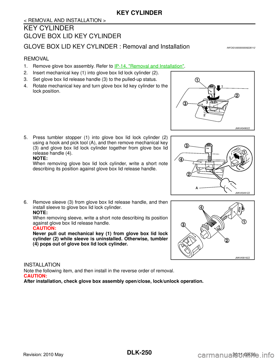
GLOVE BOX LID KEY CYLINDER : Removal and InstallationINFOID:0000000006226112
REMOVAL
1. Remove glove box assembly. Refer to IP-14, "Removal and Installation".
2. Insert mechanical key (1) into glove box lid lock cylinder (2).
3. Set glove box lid release handle (3) to the pulled-up status.
4. Rotate mechanical key and turn glove box lid key cylinder to the lock position.
5. Press tumbler stopper (1) into glove box lid lock cylinder (2) using a hook and pick tool (A), and then remove mechanical key
(3) and glove box lid lock cylinder together from glove box lid
release handle (4).
NOTE:
When removing glove box lid lock cylinder, write a short note
describing its position against glove box lid release handle.
6. Remove sleeve (3) from glove box lid release handle, and then install sleeve to glove box lid lock cylinder.
NOTE:
When removing sleeve, write a short note describing its position
against glove box lid release handle.
CAUTION:
Never pull out mechanical key (1) from glove box lid lock
cylinder (2) while sl eeve is uninstalled. Otherwise, tumbler
(4) pops out of glove box lid lock cylinder.
INSTALLATION
Note the following item, and then install in the reverse order of removal.
CAUTION:
After installation, check glove box assem bly open/close, lock/unlock operation.
JMKIA5490ZZ
JMKIA5491ZZ
JMKIA5819ZZ
Revision: 2010 May2011 QX56
Page 1792 of 5598

DLK-256
< REMOVAL AND INSTALLATION >
INSIDE KEY ANTENNA
INSIDE KEY ANTENNA
INSTRUMENT CENTER
INSTRUMENT CENTER : Removal and InstallationINFOID:0000000006226119
REMOVAL
1. Remove the cluster lid C. Refer to IP-14, "Removal and Installation".
2. Remove the inside key antenna (instrument cente r) mounting screw, and then remove inside key antenna
(instrument center).
INSTALLATION
Install in the reverse order of removal.
CONSOLE
CONSOLE : Removal and InstallationINFOID:0000000006226120
REMOVAL
1. Remove the console rear finisher. Refer to IP-29, "Removal and Installation".
2. Remove the inside key antenna (console) mounting screw, and then remove inside key antenna (con- sole).
INSTALLATION
Install in the reverse order of removal.
LUGGAGE ROOM
LUGGAGE ROOM : Removal and InstallationINFOID:0000000006226121
REMOVAL
1. Remove the second seat seatback. Refer to SE-126, "SEATBACK : Disassembly and Assembly".
2. Remove the inside key antenna (luggage room) mounting clip, and then remove inside ke\
y antenna (lug- gage room).
INSTALLATION
Install in the reverse order of removal.
Revision: 2010 May2011 QX56
Page 1793 of 5598

OUTSIDE KEY ANTENNADLK-257
< REMOVAL AND INSTALLATION >
C
DE
F
G H
I
J
L
M A
B
DLK
N
O P
OUTSIDE KEY ANTENNA
DRIVER SIDE
DRIVER SIDE : Remova l and InstallationINFOID:0000000006226122
REMOVAL
Remove the driver side outside handle. Refer to DLK-241, "OUTSIDE HANDLE : Removal and Installation".
INSTALLATION
Install in the reverse order of removal.
PASSENGER SIDE
PASSENGER SIDE : Removal and InstallationINFOID:0000000006226123
REMOVAL
Remove the passenger side outside handle. Refer to DLK-241, "OUTSIDE HANDLE : Removal and Installa-
tion".
INSTALLATION
Install in the reverse order of removal.
BACK DOOR
BACK DOOR : Removal and InstallationINFOID:0000000006226124
REMOVAL
Remove the back door finisher inner. Refer to INT-39, "Removal and Installation".
INSTALLATION
Install in the reverse order of removal.
Revision: 2010 May2011 QX56
Page 1794 of 5598

DLK-258
< REMOVAL AND INSTALLATION >
INTELLIGENT KEY WARNING BUZZER
INTELLIGENT KEY WARNING BUZZER
Removal and InstallationINFOID:0000000006226125
REMOVAL
Remove the Intelligent Key warning buzzer mounting bolt, and then remove the Intelligent Key warning
buzzer.
INSTALLATION
Install in the reverse order of removal.
Revision: 2010 May2011 QX56
Page 1795 of 5598

REMOTE KEYLESS ENTRY RECEIVERDLK-259
< REMOVAL AND INSTALLATION >
C
DE
F
G H
I
J
L
M A
B
DLK
N
O P
REMOTE KEYLESS ENTRY RECEIVER
Removal and InstallationINFOID:0000000006226126
REMOVAL
1. Remove the luggage side finisher. Refer to INT-38, "LUGGAGE SIDE UPPER FINISHER : Removal and
Installation".
2. Remove the remote keyless entry receiver mounting bolt, and then remove remote keyless entry receiver.
INSTALLATION
Install in the reverse order of removal.
Revision: 2010 May2011 QX56
Page 1796 of 5598

DLK-260
< REMOVAL AND INSTALLATION >
INTELLIGENT KEY BATTERY
INTELLIGENT KEY BATTERY
Removal and InstallationINFOID:0000000006226127
1. Release the lock knob at the back of the Intelligent Key and remove the mechanical key.
2. Insert a flat-blade screwdriver (A) wrapped with a cloth into the slit of the corner and twist it to separate the upper part from the
lower part.
CAUTION:
Do not touch the circuit board or battery terminal.
The key fob is water-resistant. However, if it does get wet,immediately wipe it dry.
3. Replace the battery with new one.
4. Align the tips of the upper and lower parts, and then push them together until it is securely closed.
CAUTION:
When replacing battery, keep dirt, grease, and other for-
eign materials off the electrode contact area.
After replacing the battery, check that all Intelligent Key
functions work normally.
PIIB6221E
Battery replacement :Coin-type lithium battery
(CR2025)
PIIB6222E
Revision: 2010 May2011 QX56