wiring INFINITI QX56 2011 Factory User Guide
[x] Cancel search | Manufacturer: INFINITI, Model Year: 2011, Model line: QX56, Model: INFINITI QX56 2011Pages: 5598, PDF Size: 94.53 MB
Page 52 of 5598

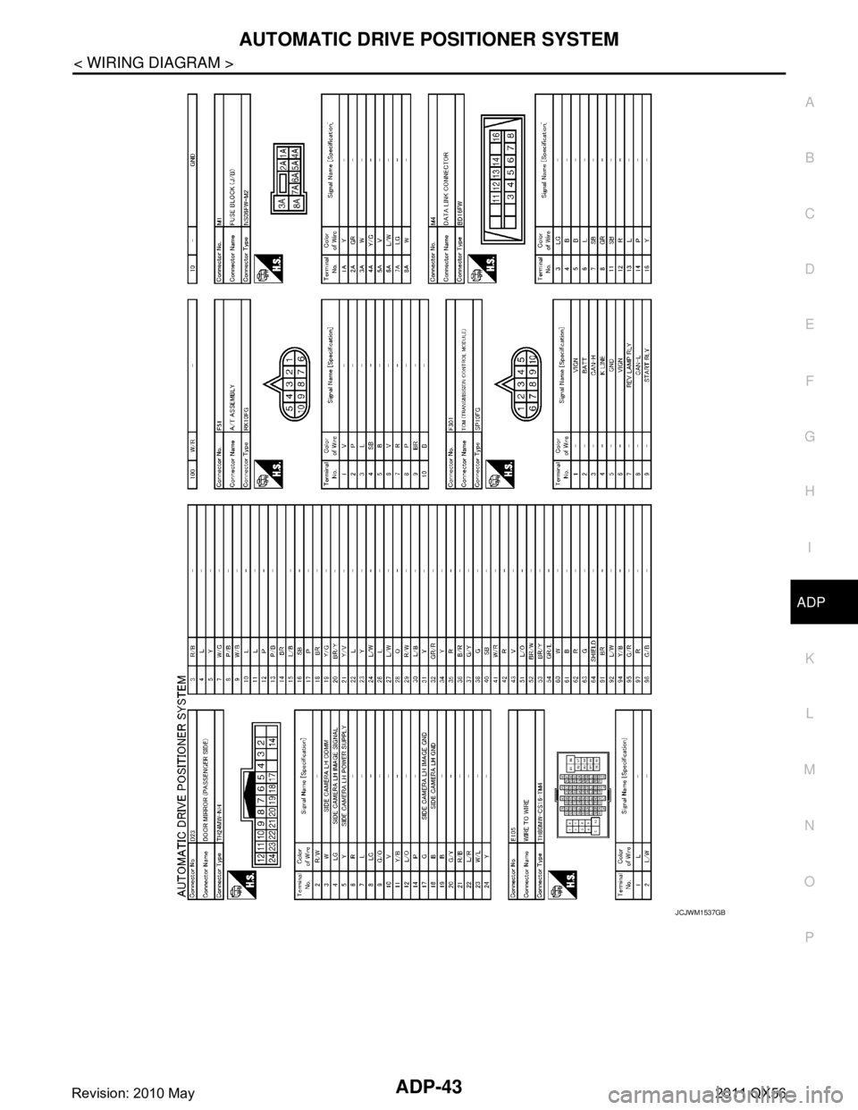
AUTOMATIC DRIVE POSITIONER SYSTEMADP-43
< WIRING DIAGRAM >
C
DE
F
G H
I
K L
M A
B
ADP
N
O P
JCJWM1537GB
Revision: 2010 May2011 QX56
Page 53 of 5598

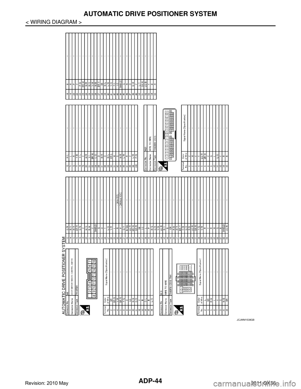
ADP-44
< WIRING DIAGRAM >
AUTOMATIC DRIVE POSITIONER SYSTEM
JCJWM1538GB
Revision: 2010 May2011 QX56
Page 54 of 5598

AUTOMATIC DRIVE POSITIONER SYSTEMADP-45
< WIRING DIAGRAM >
C
DE
F
G H
I
K L
M A
B
ADP
N
O P
JCJWM1539GB
Revision: 2010 May2011 QX56
Page 55 of 5598

ADP-46
< WIRING DIAGRAM >
AUTOMATIC DRIVE POSITIONER SYSTEM
JCJWM1540GB
Revision: 2010 May2011 QX56
Page 56 of 5598

AUTOMATIC DRIVE POSITIONER SYSTEMADP-47
< WIRING DIAGRAM >
C
DE
F
G H
I
K L
M A
B
ADP
N
O P
JCJWM1541GB
Revision: 2010 May2011 QX56
Page 65 of 5598

ADP-56
< DTC/CIRCUIT DIAGNOSIS >
U1000 CAN COMM CIRCUIT
DTC/CIRCUIT DIAGNOSIS
U1000 CAN COMM CIRCUIT
DescriptionINFOID:0000000006248336
CAN (Controller Area Network) is a serial communication line for real time applications. It is an on-vehicle mul-
tiplex communication line with high data communication speed and excellent error detection ability. Modern
vehicle is equipped with many electronic control unit, and each control unit shares information and links with
other control units during operation (not independent). In CAN communication, control units are connected
with 2 communication lines (CAN H-line, CAN L-line) al lowing a high rate of information transmission with less
wiring. Each control unit transmits/receives data but selectively reads required data only.
DTC LogicINFOID:0000000006248337
DTC DETECTION LOGIC
DTC CONFIRMATION PROCEDURE
1.STEP 1
Turn ignition switch ON and wait at least 3 seconds.
>> GO TO 2.
2.STEP 2
Check “Self diagnostic result” with CONSULT-III.
Is the DTC detected?
YES >> Perform diagnosis procedure. Refer to ADP-56, "DiagnosisProcedure".
NO >> INSPECTION END
Diagnosis ProcedureINFOID:0000000006248338
Refer to LAN-18, "Trouble Diagnosis Flow Chart".
Special Repair RequirementINFOID:0000000006248339
Refer to ADP-52, "SYSTEM INITIALIZATION : Description".
DTC No. CONSULT-III display
description DTC detecting condition Possible cause
U1000 CAN COMM CIR-
CUIT Driver seat control unit cannot communicate to other
control units.
When driver seat control unit cannot communicate CAN communication signal continuously for 2 seconds or
more. CAN communication system
Revision: 2010 May2011 QX56
Page 149 of 5598

AV
AV-1
DRIVER INFORMATION & MULTIMEDIA
C
DE
F
G H
I
J
K L
M B
SECTION AV
A
O P
CONTENTS
AUDIO, VISUAL & NAVIGATION SYSTEM
PRECAUTION ................ ...............................6
PRECAUTIONS .............................................. .....6
Precaution for Supplemental Restraint System
(SRS) "AIR BAG" and "SEAT BELT PRE-TEN-
SIONER" ............................................................. ......
6
Precaution for Trouble Diagnosis ..............................6
Precaution for Harness Repair ..................................6
PREPARATION ............................................8
PREPARATION .............................................. .....8
Commercial Service Tools .................................. ......8
SYSTEM DESCRIPTION ..............................9
COMPONENT PARTS ................................... .....9
Component Parts Location .................................. ......9
Component Description ...........................................10
SYSTEM .............................................................13
MULTI AV SYSTEM .............................................. ....13
MULTI AV SYSTEM : System Diagram ..................13
MULTI AV SYSTEM : System Description ..............14
MULTI AV SYSTEM : Fail-Sa fe .......................... ....27
DIAGNOSIS SYSTEM (AV CONTROL UNIT) ....28
Description .......................................................... ....28
On Board Diagnosis Function .................................28
CONSULT-III Function ............................................39
DIAGNOSIS SYSTEM (AROUND VIEW MON-
ITOR CONTROL UNIT) ......................................
44
On Board Diagnosis Function ............................. ....44
DIAGNOSIS SYSTEM [SONAR CONTROL
UNIT (WITH AROUND VIEW MONITOR)] .........
47
CONSULT-III Function ........................................ ....47
DIAGNOSIS SYSTEM (HEADREST DISPLAY
UNIT) ..................................................................
49
Description .......................................................... ....49
On Board Diagnosis Function .............................. ....49
ECU DIAGNOSIS INFORMATION ..............51
AV CONTROL UNIT ..........................................51
Reference Value .................................................. ....51
Fail-Safe ..................................................................57
DTC Index ...............................................................57
FRONT DISPLAY UNIT ....................................60
Reference Value ......................................................60
HEADREST DISPLAY UNIT .............................62
Reference Value ......................................................62
VIDEO DISTRIBUTOR ......................................64
Reference Value ......................................................64
BOSE AMP. .......................................................68
Reference Value ......................................................68
AROUND VIEW MONITOR CONTROL UNIT ...71
Reference Value ......................................................71
SONAR CONTROL UNIT (WITH AROUND
VIEW MONITOR) ..............................................
75
Reference Value ......................................................75
Fail-Safe ..................................................................77
DTC Index ...............................................................77
WIRING DIAGRAM ......................................78
BOSE AUDIO WITH NAVIGATION ..................78
Wiring Diagram .................................................... ....78
BASIC INSPECTION .................................104
DIAGNOSIS AND REPAIR WORK FLOW .....104
Work Flow (Multi AV) ........................................... ..104
Work Flow (Camera Assistance Sonar) ................106
ADDITIONAL SERVICE WHEN REPLACING
(AV CONTROL UNIT) .....................................
108
Revision: 2010 May2011 QX56
Page 154 of 5598

AV-6
< PRECAUTION >
PRECAUTIONS
PRECAUTION
PRECAUTIONS
Precaution for Supplemental Restraint System (SRS) "AIR BAG" and "SEAT BELT
PRE-TENSIONER"
INFOID:0000000006225819
The Supplemental Restraint System such as “A IR BAG” and “SEAT BELT PRE-TENSIONER”, used along
with a front seat belt, helps to reduce the risk or severi ty of injury to the driver and front passenger for certain
types of collision. This system includes seat belt switch inputs and dual stage front air bag modules. The SRS
system uses the seat belt switches to determine the front air bag deployment, and may only deploy one front
air bag, depending on the severity of a collision and w hether the front occupants are belted or unbelted.
Information necessary to service the system safely is included in the “SRS AIR BAG” and “SEAT BELT” of this
Service Manual.
WARNING:
• To avoid rendering the SRS inopera tive, which could increase the risk of personal injury or death in
the event of a collision that would result in air bag inflation, all maintenance must be performed by
an authorized NISS AN/INFINITI dealer.
Improper maintenance, including in correct removal and installation of the SRS, can lead to personal
injury caused by unintent ional activation of the system. For re moval of Spiral Cable and Air Bag
Module, see the “SRS AIR BAG”.
Do not use electrical test equipmen t on any circuit related to the SRS unless instructed to in this
Service Manual. SRS wiring harnesses can be identi fied by yellow and/or orange harnesses or har-
ness connectors.
PRECAUTIONS WHEN USING POWER TOOLS (AIR OR ELECTRIC) AND HAMMERS
WARNING:
When working near the Air Bag Diagnosis Sensor Unit or other Air Bag System sensors with the ignition ON or engine running, DO NOT use air or electric power tools or strike near the sensor(s)
with a hammer. Heavy vibration could activate the sensor(s) and deploy the air bag(s), possibly
causing serious injury.
When using air or electric power tools or hammers , always switch the ignition OFF, disconnect the
battery, and wait at least 3 minu tes before performing any service.
Precaution for Trouble DiagnosisINFOID:0000000006216211
AV COMMUNICATION SYSTEM
Do not apply voltage of 7.0 V or higher to the measurement terminals.
Use the tester with its open terminal voltage being 7.0 V or less.
Be sure to turn ignition switch OFF and disconnect the battery cable from the negative terminal before
checking the circuit.
Precaution for Harness RepairINFOID:0000000006216212
AV COMMUNICATION SYSTEM
Solder the repaired parts, and wrap with tape. [Frays of twisted line must be within 110 mm (4.33 in).]
PKIA0306E
Revision: 2010 May2011 QX56
Page 226 of 5598

AV-78
< WIRING DIAGRAM >
BOSE AUDIO WITH NAVIGATION
WIRING DIAGRAM
BOSE AUDIO WITH NAVIGATION
Wiring DiagramINFOID:0000000006216236
NOTE:
The name MULTIFUNCTION SWITCH indicates the integration of PRESET SWITCH and MULTIFUNCTION
SWITCH virtually.
JCNWM4811GB
Revision: 2010 May2011 QX56
Page 227 of 5598

AV
BOSE AUDIO WITH NAVIGATION
AV-79
< WIRING DIAGRAM >
C
D E
F
G H
I
J
K L
M B A
O P
JCNWM4812GB
Revision: 2010 May2011 QX56